US8670120B2 - Device for analyzing a polyphase mixture via a light beam backscattered by said mixture - Google Patents
Device for analyzing a polyphase mixture via a light beam backscattered by said mixture Download PDFInfo
- Publication number
- US8670120B2 US8670120B2 US13/131,046 US200913131046A US8670120B2 US 8670120 B2 US8670120 B2 US 8670120B2 US 200913131046 A US200913131046 A US 200913131046A US 8670120 B2 US8670120 B2 US 8670120B2
- Authority
- US
- United States
- Prior art keywords
- cell
- light beam
- polyphase mixture
- mixture
- backscattered
- Prior art date
- Legal status (The legal status is an assumption and is not a legal conclusion. Google has not performed a legal analysis and makes no representation as to the accuracy of the status listed.)
- Active, expires
Links
- 239000000203 mixture Substances 0.000 title claims abstract description 105
- 230000003287 optical effect Effects 0.000 claims abstract description 39
- 230000021615 conjugation Effects 0.000 claims abstract description 33
- 239000011159 matrix material Substances 0.000 claims abstract description 30
- 238000004458 analytical method Methods 0.000 description 11
- 238000005259 measurement Methods 0.000 description 11
- 238000012545 processing Methods 0.000 description 10
- 238000004062 sedimentation Methods 0.000 description 8
- 239000000725 suspension Substances 0.000 description 6
- 238000010521 absorption reaction Methods 0.000 description 5
- 239000000839 emulsion Substances 0.000 description 5
- 230000004907 flux Effects 0.000 description 5
- GWEVSGVZZGPLCZ-UHFFFAOYSA-N Titan oxide Chemical compound O=[Ti]=O GWEVSGVZZGPLCZ-UHFFFAOYSA-N 0.000 description 3
- 230000008901 benefit Effects 0.000 description 3
- 238000004581 coalescence Methods 0.000 description 3
- 230000005484 gravity Effects 0.000 description 3
- 239000007788 liquid Substances 0.000 description 3
- 238000000034 method Methods 0.000 description 3
- 239000002245 particle Substances 0.000 description 3
- 230000000694 effects Effects 0.000 description 2
- 238000007689 inspection Methods 0.000 description 2
- 230000005855 radiation Effects 0.000 description 2
- 239000000126 substance Substances 0.000 description 2
- XLYOFNOQVPJJNP-UHFFFAOYSA-N water Substances O XLYOFNOQVPJJNP-UHFFFAOYSA-N 0.000 description 2
- 238000012935 Averaging Methods 0.000 description 1
- 230000008859 change Effects 0.000 description 1
- 238000012512 characterization method Methods 0.000 description 1
- 230000001427 coherent effect Effects 0.000 description 1
- 230000007547 defect Effects 0.000 description 1
- 238000001514 detection method Methods 0.000 description 1
- 238000002474 experimental method Methods 0.000 description 1
- 238000005286 illumination Methods 0.000 description 1
- 238000003384 imaging method Methods 0.000 description 1
- 238000002347 injection Methods 0.000 description 1
- 239000007924 injection Substances 0.000 description 1
- 230000003993 interaction Effects 0.000 description 1
- 230000001788 irregular Effects 0.000 description 1
- 238000013508 migration Methods 0.000 description 1
- 230000005012 migration Effects 0.000 description 1
- 238000012806 monitoring device Methods 0.000 description 1
- 239000003209 petroleum derivative Substances 0.000 description 1
- 230000008569 process Effects 0.000 description 1
- 230000000750 progressive effect Effects 0.000 description 1
- 238000005070 sampling Methods 0.000 description 1
- 230000003595 spectral effect Effects 0.000 description 1
- 239000004408 titanium dioxide Substances 0.000 description 1
- 238000013519 translation Methods 0.000 description 1
Images


Classifications
-
- G—PHYSICS
- G01—MEASURING; TESTING
- G01N—INVESTIGATING OR ANALYSING MATERIALS BY DETERMINING THEIR CHEMICAL OR PHYSICAL PROPERTIES
- G01N21/00—Investigating or analysing materials by the use of optical means, i.e. using sub-millimetre waves, infrared, visible or ultraviolet light
- G01N21/17—Systems in which incident light is modified in accordance with the properties of the material investigated
- G01N21/47—Scattering, i.e. diffuse reflection
- G01N21/49—Scattering, i.e. diffuse reflection within a body or fluid
- G01N21/51—Scattering, i.e. diffuse reflection within a body or fluid inside a container, e.g. in an ampoule
-
- G—PHYSICS
- G01—MEASURING; TESTING
- G01N—INVESTIGATING OR ANALYSING MATERIALS BY DETERMINING THEIR CHEMICAL OR PHYSICAL PROPERTIES
- G01N21/00—Investigating or analysing materials by the use of optical means, i.e. using sub-millimetre waves, infrared, visible or ultraviolet light
- G01N21/17—Systems in which incident light is modified in accordance with the properties of the material investigated
- G01N21/47—Scattering, i.e. diffuse reflection
- G01N2021/4704—Angular selective
- G01N2021/4709—Backscatter
Definitions
- the present invention relates to a device for analyzing a polyphase mixture via a light beam backscattered by said mixture.
- the device may include:
- Such a device is known for example from the document US 2002/0147563.
- the measurement of the backscattered light beam with the device according to this document is not satisfactory. This is because any distance of the cell from the backscattering receiver means leads to a great loss of spatial resolution of the measurement.
- the document EP 1 241 467 is furthermore known, which relates to an apparatus for inspection and to a system for inspection of foreign matter in containers filled with a liquid.
- the monitoring device described in this document comprises in particular a light source which sends irradiation light to the transparent container, a means for taking images of the irregular reflection light reflected by the foreign matter contained in the liquid, and an image processing means detecting foreign matter in the liquid.
- the document WO 2008/092537 is furthermore known, which relates to an optical characterization device in which a sample is arranged in a light-transparent receptacle, a camera being provided in order to detect the sample.
- a first light source is arranged so that the sample is lit through in a direction counter to the line of view of the camera.
- a second light source is arranged on the same side as the camera, and a laser source is arranged transversely to the line of view of the camera.
- the document FR 2 841 983 in the name of the Applicant is also known, which relates to a method and a device for measuring a light flux backscattered by a disperse medium, not perturbed by the reflections at the interfaces; the device makes it possible to measure a light flux backscattered by a disperse medium placed on a first side of the wall, by interaction with a plurality of light rays emitted on the second side of the wall, opposite the first side where the disperse medium is placed, and in the direction of said medium, the plurality of light rays being capable of passing through the wall and being at least partially backscattered by the disperse medium in the direction of reception means placed on the second side of the wall, said wall being capable of being passed through by the emitted and backscattered light rays, and of being in contact with the disperse medium.
- the device comprises:
- a device for analyzing a polyphase mixture via a light beam backscattered by said mixture, comprising:
- the device according to the invention allows high-performance exploitation of the signal transmitted by the backscattered light beam, in combination with the means for analyzing the backscattered beam via the optical conjugation means.
- the optical conjugation means make it possible in particular to capture a part of the light beam backscattered by a point of the polyphase mixture and to transmit this beam part onto a point of the receiver means; a determined point of the receiver means, for example one or more pixels or the like, is thus made to correspond with a determined point of the mixture, this one-to-one correspondence optimizing the exploitation of the light signal transmitted by the point of the mixture which backscatters the light, by separating it from the neighboring points of the mixture which backscatter the light.
- the optical conjugation means combined with the vertical line shape of the light beam of specific thickness as defined, make it possible to obtain an analysis profile of the mixture over the analyzed height, which genuinely depends on the scattering properties of the mixture and not on the vertical line of light.
- the optical conjugation means comprise means for collecting and focusing said at least part of the backscattered light beam, of the biconvex lens type.
- This characteristic permits a one-to-one relation advantageously implemented between points of the polyphase mixture which extend over the cell height illuminated by the light beam, which itself extends in a vertical plane, and which backscatter the light, and points of the receiver means, for example pixels of a matrix sensor or the like, which is defined by a camera.
- the optical conjugation means arranged between the cell and the means for receiving the light beam backscattered by the polyphase mixture, are arranged so that the height of the receiver means is less than the height of the cell capable of containing said polyphase mixture.
- This characteristic makes it possible to reduce the size of the receiver means, and more particularly the size of the matrix sensor or the like, and therefore to reduce the cost of the device while benefiting from analysis over the entire height of the cell.
- the corresponding arrangement is advantageously obtained by an appropriate form and arrangement of the optical conjugation means between the cell and the matrix sensor or the like, so as to select an appropriate optical magnification generated by the optical conjugation means according to requirements.
- the device according to the invention furthermore comprises means for focusing the light beam emitted in the direction of the cell, taken in a horizontal cross section, at its interface between the inner surface of the wall of the cell and the polyphase mixture.
- This characteristic makes it possible to obtain an extreme thinness of the light beam striking the cell-mixture interface, thus offering a very high analysis resolution.
- the device according to the invention furthermore comprises means for extending the light beam emitted in the direction of the cell, in order to extend said beam in a vertical plane covering at least the height of the cell capable of containing said polyphase mixture, so that the light beam is divergent in said vertical plane at its interface between the inner surface of the wall of the cell and the polyphase mixture.
- Projecting a divergent beam onto the measurement cell makes it possible to adapt the measurement height to the height of the mixture to be analyzed in the cell, and more generally the height of the light beam striking the cell to the height of the cell, by modifying the divergence angle of the beam or the distance between the means generating the divergent light beam and the cell, so as to make the height of the mixture analyzed correspond to the height of the beam striking the cell at the mixture-cell interface.
- An analysis device is thus provided which can be used more flexibly than the prior art device described above in which the rays of the incident light beam, which strike the cell and are intended to be used for the analysis, have to be parallel, because for example it makes it possible to change the cell easily.
- the divergent incident beam makes it possible to use emitter means which are smaller than the height of the cell and also makes it possible to avoid using focusing means which are excessively large and therefore expensive.
- said means for emitting the light beam in the direction of the cell comprise:
- said means for extending the light beam emitted in the direction of the cell comprise vertically divergent concave cylindrical lens means.
- said focusing means are arranged between the means for generating the beam of collimated light and the means for extending the light beam in the vertical plane.
- said means for emitting the light beam in the direction of the cell comprise means for generating at least one divergent light beam.
- said focusing means comprise convergent lens means.
- said focusing means comprise horizontally convergent cylindrical lens means.
- said means for generating at least one divergent light beam comprise a linear light source.
- said linear light source comprises a plurality of divergent point light sources.
- the cell capable of containing said polyphase mixture has a vertical right cylindrical shape.
- the cell of vertical right cylindrical shape has a circular cross section.
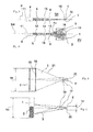
- FIG. 1 represents a schematic perspective view of a first exemplary embodiment of a device according to the invention for analyzing a polyphase mixture by means of a light beam backscattered by said mixture.
- FIG. 2 represents a schematic perspective view of a second exemplary embodiment of a device according to the invention, which is partial and concerns the means for emitting a light beam in the direction of the cell.
- FIG. 3 represents a view from above of the example in FIG. 2 .
- FIG. 4 represents a side view of the example in FIG. 2 .
- FIG. 5 represents a partial schematic side view of the example in FIG. 1 , relating to the means for receiving the backscattered light beam.
- FIG. 6 represents a similar view to FIG. 5 , showing a detail of the backscattered light beam.
- FIG. 7 represents a view from above of FIG. 6 with a different cell having a square cross section.
- FIG. 8 represents a schematic perspective view of a third exemplary embodiment of a device according to the invention, which is partial and concerns the means for emitting a light beam in the direction of the cell.
- FIG. 9 represents a view from above of the example in FIG. 8 .
- FIG. 10 represents a side view of the example in FIG. 8 .
- FIG. 11 represents a schematic perspective view of a fourth exemplary embodiment of a device according to the invention, which is partial and concerns the means for emitting a light beam in the direction of the cell.
- FIG. 12 represents a view from above of the example in FIG. 11 .
- FIG. 13 represents a side view of the example in FIG. 11 .
- FIG. 14 represents a view of the backscattering image obtained on the receiver matrix sensor, for an arbitrary mixture.
- FIG. 15 represents an example of processing of the image according to FIG. 14 .
- FIGS. 16 to 18 relate to a first example of use of a device according to the invention, for studying sedimentation.
- FIGS. 19 and 20 relate to a second example of use of a device according to the invention, for studying the creaming of an emulsion.
- FIGS. 21 and 22 relate to a third example of use of a device according to the invention, for studying the coalescence of an emulsion.
- the device for analyzing a polyphase mixture 2 via a light beam 3 backscattered by said mixture represented schematically in FIG. 1 comprises:
- the polyphase mixture 2 analyzed may be of any type, for example a polyphase mixture for which it is desired to analyze the phases, in particular the detection and measurement of phenomena, for example nascent phenomena, of demixing or sedimentation in mixtures as a function of time, for example of emulsions or suspensions.
- the fields of application of the analysis device according to the invention comprise in particular the chemical and parachemical industry, and more generally all fields for which it is necessary to analyze the structure as well as the stability of a polyphase mixture or ascertain the structure of a mixture or more generally a scattering medium.
- the cell 1 having a capacity component of vertical extent, capable of containing the polyphase mixture 2 may for example be a cell having a vertical right cylindrical shape, for example having a circular cross section as represented in FIG. 1 .
- Other shapes of cell and/or cross sections may be suitable, for example having a polygonal, in particular square, cross section, so long as they have a capacity comprising a vertical extent along which gravity can exert its effects, preferably comprising at least one vertical straight wall part illuminated by the light beam 5 .
- the device preferably comprises a rigid support (not shown) intended to be placed on a surface which is fixed with respect to gravity which makes it possible to place and hold:
- the analysis means 7 may be in the form of management electronics fixed to the support or arranged in a housing connected thereto.
- the device advantageously comprises means for extending the light beam 5 emitted in the direction of the cell 1 , in order to extend said beam in the vertical plane PV covering at least the height hc of the cell 1 containing the polyphase mixture 2 , so that the light beam 5 is divergent in the vertical plane PV at its interface 9 between the inner surface 10 of the wall 18 of the cell 1 and the polyphase mixture 2 .
- these extension means are obtained by virtue of means 4 , for emitting the light beam 5 in the direction of the cell 1 , which comprise means 30 for generating at least one divergent light beam 31 .
- the generator means 30 may, for example, consist of a generator of a vertical line of laser light diverging at the source in a vertical plane.
- the optical conjugation means 17 allow one and only one point of the matrix sensor 20 to be made to correspond with each point of the scattering pattern on the surface of the mixture 2 analyzed. Measuring the light flux arriving on the matrix sensor 20 will thus be equivalent to measuring the surface flux density at each point of the scattering pattern.
- the backscattered light is emitted with an equal intensity in all directions. The Applicant has thus observed that the intensity on the sensor corresponds to that emitted by the product even if the collection optics are placed so that they receive the light from each point of the surface of the mixture at different angles.
- the optical conjugation means 17 advantageously comprise means for collecting and focusing a part of the backscattered light beam, such as a simple biconvex lens 19 as represented in the figures, or of an optically equivalent type, for example a doublet or a triplet, or the like.
- the part of the backscattered light beam 3 collected by the optical conjugation means 17 furthermore extends in the horizontal direction, as represented in FIGS. 1 and 7 , so as to collect information about the backscattered light on both sides of the vertical line of light incident on the cell 1 , for example over the entire illuminated wall in the case of a cell 1 with a cross section which is polygonal, in particular square or rectangular as represented in FIG. 7 , or over a part, shaped as an arc of a cylinder, of the cell 1 with a circular cross section, for which the incident vertical line of light lies in a substantially median position, as represented in FIG. 1 .
- the optical conjugation means 17 arranged between the cell 1 and the means 6 for receiving the light beam 3 backscattered by the polyphase mixture 2 , are advantageously arranged so that the height hr of the receiver means is less than the height hc of the cell 1 capable of containing the polyphase mixture 2 , as represented in the figures.
- the optical conjugation means 17 are preferably placed at a height substantially equal to half the height of the cell 1 , i.e. hc/2, in order to be equidistant between top and bottom interfaces of the illuminated mixture 2 when it completely fills the cell (not shown in the figures). Furthermore, the plane of the biconvex lens 19 or the like is preferably placed parallel to the interface 9 illuminated by the emitter means 4 , which lies between the mixture 2 and the inner surface 10 of the wall 18 of the cell 1 in contact with said mixture.
- the biconvex lens 19 is defined by its magnification, and arranged between the matrix sensor and the cell 1 , so that the image of the backscattered light extending over the mixture height is transmitted to the matrix sensor 20 and corresponds to the selected height of said sensor, as shown in FIG. 5 .
- a similar principle is applied for the selected width of the matrix sensor 20 , i.e. in order to conjugate the cell 1 with the size of the matrix sensor 20 while taking into account the cell width over which it is desired to obtain information relating to the backscattered light.
- FIG. 1 shows this conjugation in perspective.
- FIGS. 6 and 7 show the one-to-one relations in a vertical plane and in a horizontal plane between two points of the mixture 2 , of which it is desired to obtain information by the light which is backscattered from these points, and two points of the matrix sensor 20 .
- the optical conjugation means 17 and the matrix sensor 20 may advantageously be placed symmetrically with respect to a vertical plane which is perpendicular to the wall 18 of the cell 1 , onto which the incident light beam is projected, and which comprises the line of light, or with respect to a plane intersecting with the plane defined above along the line of light and forming an angle with this plane defined above.
- FIGS. 1 and 5 represent the optical field 21 by lines which connect the upper and lower ends of the cell 1 respectively to the lower and upper ends of the matrix sensor 20 , the optical field being defined by the arrangement of the optical conjugation means 17 , as a function of the ratio which is desired between the height of the cell 1 and that of the matrix sensor 20 , and also as a function of the distance separating the cell from the matrix sensor 20 .
- FIGS. 2 to 4 show a second embodiment of the generation of the light beam 5 emitted in the direction of the cell 1 , comprising means for extending the beam in the vertical plane.
- the device according to the invention advantageously comprises means 14 for focusing the light beam 5 emitted in the direction of the cell 1 , in order to focus this light beam 5 , taken in a horizontal cross section SH, at its interface 9 between the inner surface 10 of the wall 18 of the cell 1 and the polyphase mixture 2 .
- the means 4 for emitting the light beam 5 in the direction of the cell 1 advantageously comprise:
- the means 8 for extending the light beam 5 emitted in the direction of the cell 1 comprise, for example, divergent lens means on a (cylindrical) axis, for example a vertically divergent concave cylindrical lens 13 .
- the focusing means 14 make it possible to obtain according to the invention a light beam 5 emitted in the direction of the cell, at its interface 9 between the inner surface 10 of the wall 18 of the cell 1 and the polyphase mixture 2 , which has a vertical line shape 16 whose width is less, preferably very much less, than the free transport path l* of the polyphase mixture 2 , as will be detailed below with the description of the analysis means 7 .
- These focusing means 14 in the example of FIGS. 2 to 4 , consist of convergent lens means 15 , for example an at least horizontally convergent cylindrical lens: in the example represented in these figures, a biconvex lens focusing the beam emitted by the generator means 11 toward a point. As represented in FIGS.
- the focused beam 5 then passes through the vertically divergent concave cylindrical lens 13 which diverges the beam 5 in the vertical plane before reaching the cell, without modifying the convergence of the beam 5 given by the lens 15 in the horizontal plane, as shown in FIG. 3 .
- the arrangement of the focusing means 14 makes it possible to offer the device according to the invention a light beam thinness which can advantageously be modified, for example by adjusting the position of the lens or the emitting source with respect to the cell.
- FIGS. 8 to 10 show a third embodiment of the generation of a light beam 5 emitted in the direction of the cell 1 , comprising means for extending the beam in the vertical plane in the manner of the first and second embodiments.
- the means 30 for generating a divergent light beam 31 comprise a bare laser source 30 producing an initial light beam which is divergent in the horizontal and vertical planes. This initial light beam is focused in a horizontal plane by focusing means 14 consisting, for example, of a horizontally convergent cylindrical lens as represented in FIGS. 8 and 9 .
- FIGS. 11 to 13 show a fourth embodiment of the generation of a light beam 5 emitted in the direction of the cell 1 , comprising means for extending the beam in the vertical plane in the manner of the other embodiments.
- the means 30 for generating a divergent light beam 31 comprise a linear light source 41 comprising plurality of juxtaposed divergent point light sources 42 producing an initial light beam which is divergent in the horizontal and vertical planes.
- This initial light beam is focused in a horizontal plane by focusing means 14 consisting, for example, of a convergent conjugation lens as represented in FIGS. 11 to 13 .
- any means for projecting a line of light may be used, for example the projection of a line-shaped mask of the photographic slide type. It is not necessary to use a coherent light source, such as a laser is. A laser is advantageous because it makes it possible to obtain a thin light beam having a high light intensity relatively easily.
- the line of light 16 may have a width which gives it the shape of an elongate rectangle.
- a rectangle has the benefit of optically averaging a possible irregularity of the mixture itself.
- this shape may consist of merely stretching an arbitrary profile along the vertical axis.
- the wavelength of the light may be selected as a function, for example, of the spectral absorption of the product. Specifically, it is often advantageous to work with a wavelength for which the product has little absorption. For example, the near infrared range for petroleum products. Each light point of this line of light 16 will be spread to a greater or lesser extent horizontally as a function of the local scattering properties of the product.
- the almost ideal line of light 16 will be deformed, and widened to a greater or lesser extent.
- This deformation along the height, picked up by the matrix sensor 20 via the optical conjugation means 17 will provide information about the variations in scattering properties of the product along the height.
- the matrix sensor 20 may be provided by a 2D matrix of the CCD or CMOS type.
- a distance between the matrix sensor 20 and the cell 1 immediately leads to a great loss of spatial resolution of the measurement. This is because the backscattered light essentially consists of rays which are distributed in all directions and a distance from the sensor thus leads to a strong blurring effect.
- the sensor could be transparent, which is possible, but not standard and would therefore entail a very large extra cost. It is possible to use a very inexpensive video sensor.
- the flexible nature allows the device according to the invention to be adapted readily to a given family of chemical products and allows a range of instruments to be designed easily for these families, for example for highly scattering products (high resolution).
- the device according to the invention therefore allows good market satisfaction.
- the measurement may be carried out through a window, which makes it possible to put the cell containing the mixture to be analyzed in a chamber of moderate volume (of the order of 1 dm 3 ). This small volume allows easy implementation of thermal and/or humidity level regulation or the like.
- the means 7 for analyzing the part of the light beam 3 backscattered by the polyphase mixture 2 and received by the matrix sensor 6 via the optical conjugation means 17 will now be described with the aid of FIGS. 14 to 15 .
- FIGS. 14 to 22 show examples of a mixture analyzed with a device as described above.
- the pixels of a horizontal line of the matrix sensor 20 may be selected, corresponding to a given height h 1 , h 2 , etc. . . . on the cell 1 .
- a curve is thus obtained ( FIG. 15 ) of light intensity (on the ordinate) as a function of the transverse coordinate (on the abscissa) for each height h 1 , h 2 , etc. This curve is referred to as a “transverse profile”.
- Advantageous processing operations may be those which for each measurement, i.e. an illumination over the height of the mixture analyzed at a time t, give a curve as a function of the vertical coordinate (height). In order to do this, it is necessary to convert each “transverse profile” into a simple number representative of the scattering properties of the product analyzed.
- a first example of “transverse profile” processing would simply be the value of the light intensity at the center of the profile.
- Another example would be to measure the width of the “transverse profile”. For example the width at half height of each curve on FIG. 15 , or alternatively the width of a Gaussian curve fitted to the profile, or else a statistical width: LX [ ⁇ I(x)x 2 dx/(x)dx] 1/2 with I(x) representing the light intensity of the profile for the transverse coordinate x (with the origin at the center of the profile).
- I 0 representing the light intensity at the point source S.
- the Applicant has observed that illuminating the analyzed medium along a line of light causes, in backscattering, perturbations of the backscattered light picked up by the receiver means, consisting of the light backscattered by a determined point of the illuminated mixture being merged with the light simultaneously backscattered by the adjacent points above and below the point in question. These perturbations modify the nature of the backscattered signal picked up, and it is therefore advantageous to provide specific means for analysis over the height of the illuminated cell, which take these perturbations into account.
- the decrease being proportional to the square of the distance to the source, with I 0 representing the light intensity at the point source L.
- the device according to the invention makes it possible to give a measurement both of the absorption (length l a ) and of the scattering (length l*).
- l* is the equivalent mean free path for isotropic scattering, or in other words the distance beyond which the photon which enters the product has completely lost its initial direction.
- l* is the standard physical parameter for characterizing the scattering properties of the product. If l*, the concentration and the optical indices are known, it is for example possible to calculate the diameter of the particles by methods known to the person skilled in the art. Let us also recall that l a is the length of the path of the photon before being absorbed; its value is infinite for white products and tends toward zero for dark products.
- An optical head is intended to mean a part of the analysis device comprising the emitter means 4 , the receiver means 6 , and the optical conjugation means 17 .
- a kind of carousel may be envisaged which makes it possible to accommodate a plurality of cells, or alternatively a row of cells on a straight support (these are not shown).
- the optical head rotates at the center of the carousel so as to successively measure each cell or flask of product or mixture to be analyzed. Possible misalignments due to mechanical defects of the rotating system may perfectly well be corrected by software.
- the optical head moves or the cell support moves, in translation with respect to one another, so as to successively measure each cell of product.
- FIGS. 16 , 17 and 18 represent a first example of use of a device according to the invention as described above, for studying the sedimentation of a suspension of titanium dioxide (TiO 2 ) in water.
- the experiment carried out is as follows: the suspension has a volume fraction of 3.8%. The average size of the titanium dioxide particles is 2 micrometers.
- the suspension is placed in a cylindrical receptacle with a diameter of 28 mm and a height of 50 mm, having a transparent wall.
- the suspension is first homogenized then placed in an analysis device according to the invention. A measurement over the entire height in backscattering is carried out every 10 minutes for 13 hours.
- FIG. 17 represents a series of curves which are obtained after having used the processing which gives the value of the area under the “transverse profiles” on the ordinate for each cell height defined on the abscissa, as described above.
- FIG. 16 represents the appearance of an image of the scattering pattern. This is a raw image. On the curves in FIG. 17 , a variation of the straight part of the profile can be seen (top part of the suspension), which clearly indicates progressive descent of the sedimentation front.
- the sedimentation rate may be given by plotting the height of the sedimentation front as a function of time, as represented in FIG. 18 on which the slope of the curve corresponds to the sedimentation rate.
- the sedimentation rate is 184.6 micrometers per hour on average.
- FIGS. 19 and 20 represent a second example of use of a device according to the invention as described above, relating to an example of measuring the creaming of an emulsion over 26 minutes by using the “integral under the profile” processing described above.
- FIG. 19 shows a series of curves which are obtained after having used the processing which gives the value of the area under the “transverse profiles” on the ordinate for each height defined on the abscissa.
- FIG. 20 shows the height of the creaming front (on the ordinate) as a function of time (on the abscissa). The slope of the curve represents the creaming rate.
- FIGS. 21 and 22 represent a third example of use of a device according to the invention as described above, relating to an example of measuring the coalescence of an emulsion over 8 minutes by using the “integral under the profile” processing described above.
- the drops of oil combine to form larger drops.
- the size variation modifies the height of the signal. There is no particle migration, so the signal remains uniform.
- FIG. 21 shows a series of curves which are obtained for coalescence of drops.
- FIG. 22 represents the kinetics showing the drop in the signal.
Landscapes
- Physics & Mathematics (AREA)
- Health & Medical Sciences (AREA)
- Life Sciences & Earth Sciences (AREA)
- Chemical & Material Sciences (AREA)
- Analytical Chemistry (AREA)
- Biochemistry (AREA)
- General Health & Medical Sciences (AREA)
- General Physics & Mathematics (AREA)
- Immunology (AREA)
- Pathology (AREA)
- Investigating Or Analysing Materials By Optical Means (AREA)
Abstract
Description
-
- a cell having a capacity component of vertical extent, capable of containing the polyphase mixture,
- means for emitting a light beam in the direction of the cell, so that the light beam extends in a vertical plane covering at least a height of the cell capable of containing the polyphase mixture,
- means for receiving the light beam backscattered by said polyphase mixture, covering a backscattered light beam height extending over the height of the cell capable of containing the polyphase mixture.
-
- means for emitting, toward the wall, light radiation capable of passing through this wall and reaching the disperse medium, so that the latter can in turn emit a plurality of backscattered light rays through the wall with a view to forming a backscattering spot in which at least one central disk-shaped region is defined, the center of which corresponds to the light centroid of the backscattering spot and the radius of which is equal to four times the maximum free transport path l*max of the disperse medium, the backscattering spot being capable of being imaged at least in part on the reception means,
- means for receiving the light radiation backscattered by the disperse medium through the wall and intended to form the backscattering spot, these reception means covering at least a direction extending from the light centroid of said spot,
- means for suppressing, from the light rays backscattered by the disperse medium, the light rays which come from the central region and have experienced total reflection on the surface forming the interface of the wall with the second side,
- means for measuring spatial sampling of the profile of the light flux received by at least a part of the reception means.
-
- a cell having a capacity component of vertical extent, capable of containing the polyphase mixture,
- means for emitting a light beam in the direction of the cell, so that the light beam extends in a vertical plane covering at least a height of the cell containing the polyphase mixture,
- means for receiving at least a part of the light beam backscattered by said polyphase mixture, covering a backscattered light beam height extending over the height of the cell containing the polyphase mixture, characterized in that it furthermore comprises:
- optical conjugation means arranged between the cell and the means for receiving at least a part of the light beam backscattered by the polyphase mixture,
- said receiver means comprising a matrix sensor provided with a plurality of pixels or the like, forming a surface extending along a vertical direction and a horizontal direction,
- means for analyzing said at least part of the light beam backscattered by the polyphase mixture and received by the matrix sensor via the optical conjugation means,
- the light beam emitted in the direction of the cell having, at its interface between the inner surface of the wall of the cell and the polyphase mixture, a vertical line shape whose width is less, preferably very much less, than the free transport path l* of the polyphase mixture.
-
- means for generating a light beam, all the light rays of which are mutually parallel,
- said means for extending the light beam emitted in the direction of the cell being interposed between said means for generating a collimated light beam and the cell.
-
- a
cell 1 having a capacity component of vertical extent, capable of containing thepolyphase mixture 2, - means 4 for emitting a
light beam 5 in the direction of thecell 1, so that thelight beam 5 extends in a vertical plane PV covering at least a height hc of thecell 1 containing thepolyphase mixture 2, - means 6 for receiving at least a part of the
light beam 3 backscattered by thepolyphase mixture 2, covering a backscatteredlight beam 3 height extending over the height hc of thecell 1 containing thepolyphase mixture 2, - optical conjugation means 17 arranged between the
cell 1 and themeans 6 for receiving at least a part of thelight beam 3 backscattered by thepolyphase mixture 2, - the receiver means 6 comprising a
matrix sensor 20 provided with a plurality of pixels or the like, forming a surface for receiving the part of the backscatteredlight beam 3 passing through the optical conjugation means 17, extending along a vertical direction and a horizontal direction, - means 7 for analyzing the part of the
light beam 3 backscattered by thepolyphase mixture 2 and received by thematrix sensor 20 via the optical conjugation means 17.
- a
-
- the
cell 1 in its vertical position, - the
means 4 for emitting thelight beam 5 in the direction of thecell 1, and - the
means 6 for receiving a backscattered light beam, comprising thematrix sensor 20, - the optical conjugation means 17.
- the
-
- the
means 11 for generating alight beam 12, all the light rays of which are mutually parallel, which is referred to as acollimated light beam 12, for example a collimated laser source, - the
means 8 for extending thelight beam 5 emitted in the direction of thecell 1 being interposed between themeans 11 for generating the collimatedlight beam 12 and thecell 1, and - the focusing means 14 being arranged between the
means 11 for generating the beam of collimatedlight 12 and themeans 8 for extending thelight beam 5 in the vertical plane PV.
- the
I(r)=I 0 /r 3,
I(x)=2I 0 /x 2,
Claims (20)
Applications Claiming Priority (3)
| Application Number | Priority Date | Filing Date | Title |
|---|---|---|---|
| FR0858030 | 2008-11-26 | ||
| FR0858030A FR2938917B1 (en) | 2008-11-26 | 2008-11-26 | DEVICE FOR ANALYZING A POLYPHASIC MIXTURE VIA A LIGHT BEAM RETRODIFFUSED THEREBY |
| PCT/FR2009/052303 WO2010061137A1 (en) | 2008-11-26 | 2009-11-26 | Device for analyzing a polyphase mixture via a light beam backscattered by said mixture |
Publications (2)
| Publication Number | Publication Date |
|---|---|
| US20110228272A1 US20110228272A1 (en) | 2011-09-22 |
| US8670120B2 true US8670120B2 (en) | 2014-03-11 |
Family
ID=40750940
Family Applications (1)
| Application Number | Title | Priority Date | Filing Date |
|---|---|---|---|
| US13/131,046 Active 2030-10-08 US8670120B2 (en) | 2008-11-26 | 2009-11-26 | Device for analyzing a polyphase mixture via a light beam backscattered by said mixture |
Country Status (5)
| Country | Link |
|---|---|
| US (1) | US8670120B2 (en) |
| EP (1) | EP2356429B1 (en) |
| CN (1) | CN102272579B (en) |
| FR (1) | FR2938917B1 (en) |
| WO (1) | WO2010061137A1 (en) |
Cited By (3)
| Publication number | Priority date | Publication date | Assignee | Title |
|---|---|---|---|---|
| US9316577B1 (en) | 2015-07-10 | 2016-04-19 | David E. Doggett | Oscillatory particle analyzer |
| US9366617B1 (en) * | 2015-07-10 | 2016-06-14 | David E. Doggett | Self-stirring container |
| US9677988B1 (en) * | 2015-07-10 | 2017-06-13 | David E. Doggett | Integrating radiation collection and detection apparatus |
Families Citing this family (4)
| Publication number | Priority date | Publication date | Assignee | Title |
|---|---|---|---|---|
| EP2378270B1 (en) * | 2010-04-15 | 2015-06-24 | SICK Engineering GmbH | Method for determining particle concentration and measuring device |
| FR2997502B1 (en) * | 2012-10-29 | 2014-12-26 | Commissariat Energie Atomique | METHOD FOR OBSERVING BIOLOGICAL SPECIES |
| FR3003351B1 (en) * | 2013-03-12 | 2015-03-13 | Formulaction | APPARATUS FOR ANALYZING PHASES OF POLYPHASIC MIXTURES |
| CN106248603B (en) * | 2016-09-27 | 2019-09-24 | 济南恒辉科济食品配料有限公司 | Food is suspended and opaque system Stability Determination detection method and detection device |
Citations (19)
| Publication number | Priority date | Publication date | Assignee | Title |
|---|---|---|---|---|
| US4028553A (en) | 1974-06-27 | 1977-06-07 | Michel Farcinade | Apparatus for controlling pharmaceutical ampoules |
| US5523560A (en) | 1991-02-01 | 1996-06-04 | Novonordisk A/S | Method and apparatus for inspecting liquid-filled containers |
| US5619043A (en) * | 1994-09-21 | 1997-04-08 | Laser Sensor Technology, Inc. | System for acquiring an image of a multi-phase fluid by measuring backscattered light |
| US5783826A (en) * | 1994-05-17 | 1998-07-21 | Meunier; Gerard | Method and apparatus for analyzing the phases of a multi-phase mixture |
| US6091492A (en) * | 1994-04-15 | 2000-07-18 | Micromeritics Instrument Corporation | Apparatus and method for determining the size distribution of particles by light scattering |
| EP1241467A2 (en) | 2001-03-14 | 2002-09-18 | Hitachi Engineering Co., Ltd. | Inspection device and system for inspecting foreign matters in liquid filled in transparent container |
| US20020147563A1 (en) * | 2001-02-26 | 2002-10-10 | Dietmar Lerche | Method and device for accelerated stability analysis |
| US6466319B2 (en) * | 2000-04-07 | 2002-10-15 | Rohm And Haas Company | Method and apparatus for determining the dispersion stability of a liquid suspension |
| FR2841983A1 (en) | 2002-07-02 | 2004-01-09 | Formulaction | METHOD AND DEVICE FOR MEASURING A LIGHT FLOW RETRODUCTED BY A DISPERSE MEDIUM, NOT PERTURBED BY REFLECTIONS AT THE INTERFACES |
| US6765656B2 (en) * | 2001-12-18 | 2004-07-20 | University Of Wyoming | Apparatus and methods for high throughput analysis of samples in a translucent flowing liquid |
| WO2005001449A1 (en) | 2003-06-27 | 2005-01-06 | Commissariat A L'energie Atomique | Method for dosing a biological or chemical sample |
| WO2006023470A1 (en) | 2004-08-19 | 2006-03-02 | Becton, Dickinson And Company | Apparatus for performing optical measurements on blood culture bottles |
| GB2420403A (en) | 2004-11-23 | 2006-05-24 | Danisco | Analysing a food sample by the use of light scattering |
| US7268874B2 (en) * | 2001-06-18 | 2007-09-11 | Infm Istituto Nazionale Per La Fisica Della Materia | Method of measuring properties of dispersed particles in a container and corresponding apparatus |
| WO2008092535A1 (en) | 2007-01-31 | 2008-08-07 | Endress+Hauser Flowtec Ag | Measuring pipe for a flowmeter |
| US20100007891A1 (en) * | 2008-07-08 | 2010-01-14 | Brunob Ii B.V. | Methods of and Apparatus for Determining Properties Relating to Multi-Phase Systems |
| US7782458B2 (en) * | 2003-09-25 | 2010-08-24 | Formulaction | Method and device for the analysis of movement in a scattering medium |
| US8149418B2 (en) * | 2005-09-29 | 2012-04-03 | The General Hospital Corporation | Method and apparatus for optical imaging via spectral encoding |
| US8368747B2 (en) * | 2007-01-29 | 2013-02-05 | Robert Bosch Gmbh | Device for optical characterization |
Family Cites Families (3)
| Publication number | Priority date | Publication date | Assignee | Title |
|---|---|---|---|---|
| US5120979A (en) * | 1991-03-25 | 1992-06-09 | Becton, Dickinson And Company | Apparatus and method for analysis of a sample medium in a gap between a tube and a float |
| US6097786A (en) * | 1998-05-18 | 2000-08-01 | Schlumberger Technology Corporation | Method and apparatus for measuring multiphase flows |
| CN100516839C (en) * | 2007-11-06 | 2009-07-22 | 山东大学 | Device and method for measuring rapidly coherent backscattering using area array CCD |
-
2008
- 2008-11-26 FR FR0858030A patent/FR2938917B1/en active Active
-
2009
- 2009-11-26 US US13/131,046 patent/US8670120B2/en active Active
- 2009-11-26 WO PCT/FR2009/052303 patent/WO2010061137A1/en active Application Filing
- 2009-11-26 EP EP09797092.5A patent/EP2356429B1/en active Active
- 2009-11-26 CN CN200980153517.1A patent/CN102272579B/en active Active
Patent Citations (21)
| Publication number | Priority date | Publication date | Assignee | Title |
|---|---|---|---|---|
| US4028553A (en) | 1974-06-27 | 1977-06-07 | Michel Farcinade | Apparatus for controlling pharmaceutical ampoules |
| US5523560A (en) | 1991-02-01 | 1996-06-04 | Novonordisk A/S | Method and apparatus for inspecting liquid-filled containers |
| US6091492A (en) * | 1994-04-15 | 2000-07-18 | Micromeritics Instrument Corporation | Apparatus and method for determining the size distribution of particles by light scattering |
| US5783826A (en) * | 1994-05-17 | 1998-07-21 | Meunier; Gerard | Method and apparatus for analyzing the phases of a multi-phase mixture |
| US5619043A (en) * | 1994-09-21 | 1997-04-08 | Laser Sensor Technology, Inc. | System for acquiring an image of a multi-phase fluid by measuring backscattered light |
| US6466319B2 (en) * | 2000-04-07 | 2002-10-15 | Rohm And Haas Company | Method and apparatus for determining the dispersion stability of a liquid suspension |
| US20020147563A1 (en) * | 2001-02-26 | 2002-10-10 | Dietmar Lerche | Method and device for accelerated stability analysis |
| EP1241467A2 (en) | 2001-03-14 | 2002-09-18 | Hitachi Engineering Co., Ltd. | Inspection device and system for inspecting foreign matters in liquid filled in transparent container |
| US7268874B2 (en) * | 2001-06-18 | 2007-09-11 | Infm Istituto Nazionale Per La Fisica Della Materia | Method of measuring properties of dispersed particles in a container and corresponding apparatus |
| US6765656B2 (en) * | 2001-12-18 | 2004-07-20 | University Of Wyoming | Apparatus and methods for high throughput analysis of samples in a translucent flowing liquid |
| US20060061766A1 (en) | 2002-07-02 | 2006-03-23 | Laurent Brunel | Method and device for measuring a light flux backscattered by a dispersed medium, unperturbed by interface reflections |
| FR2841983A1 (en) | 2002-07-02 | 2004-01-09 | Formulaction | METHOD AND DEVICE FOR MEASURING A LIGHT FLOW RETRODUCTED BY A DISPERSE MEDIUM, NOT PERTURBED BY REFLECTIONS AT THE INTERFACES |
| WO2005001449A1 (en) | 2003-06-27 | 2005-01-06 | Commissariat A L'energie Atomique | Method for dosing a biological or chemical sample |
| US7782458B2 (en) * | 2003-09-25 | 2010-08-24 | Formulaction | Method and device for the analysis of movement in a scattering medium |
| WO2006023470A1 (en) | 2004-08-19 | 2006-03-02 | Becton, Dickinson And Company | Apparatus for performing optical measurements on blood culture bottles |
| US7643134B2 (en) * | 2004-08-19 | 2010-01-05 | Becton, Dickinson And Company | Apparatus for performing optical measurements on blood culture bottles |
| GB2420403A (en) | 2004-11-23 | 2006-05-24 | Danisco | Analysing a food sample by the use of light scattering |
| US8149418B2 (en) * | 2005-09-29 | 2012-04-03 | The General Hospital Corporation | Method and apparatus for optical imaging via spectral encoding |
| US8368747B2 (en) * | 2007-01-29 | 2013-02-05 | Robert Bosch Gmbh | Device for optical characterization |
| WO2008092535A1 (en) | 2007-01-31 | 2008-08-07 | Endress+Hauser Flowtec Ag | Measuring pipe for a flowmeter |
| US20100007891A1 (en) * | 2008-07-08 | 2010-01-14 | Brunob Ii B.V. | Methods of and Apparatus for Determining Properties Relating to Multi-Phase Systems |
Cited By (3)
| Publication number | Priority date | Publication date | Assignee | Title |
|---|---|---|---|---|
| US9316577B1 (en) | 2015-07-10 | 2016-04-19 | David E. Doggett | Oscillatory particle analyzer |
| US9366617B1 (en) * | 2015-07-10 | 2016-06-14 | David E. Doggett | Self-stirring container |
| US9677988B1 (en) * | 2015-07-10 | 2017-06-13 | David E. Doggett | Integrating radiation collection and detection apparatus |
Also Published As
| Publication number | Publication date |
|---|---|
| FR2938917A1 (en) | 2010-05-28 |
| FR2938917B1 (en) | 2018-05-18 |
| EP2356429B1 (en) | 2019-06-05 |
| CN102272579B (en) | 2014-07-02 |
| WO2010061137A1 (en) | 2010-06-03 |
| EP2356429A1 (en) | 2011-08-17 |
| US20110228272A1 (en) | 2011-09-22 |
| CN102272579A (en) | 2011-12-07 |
Similar Documents
| Publication | Publication Date | Title |
|---|---|---|
| US8670120B2 (en) | Device for analyzing a polyphase mixture via a light beam backscattered by said mixture | |
| US7430047B2 (en) | Small container fluid dynamics to produce optimized inspection conditions | |
| US6782122B1 (en) | Apparatus for measuring height of a liquid in a container using area image pattern recognition techniques | |
| JP2020173260A (en) | Method and apparatus for scanning bones in meat | |
| AU2006321716B2 (en) | Method and apparatus for quantifying pigment dispersion quality by paint drawdown | |
| CN110389021A (en) | Lenticular image generation system and refractive power and thickness determination and defect inspection method | |
| JPH09504095A (en) | Optical component inspection system | |
| KR101482580B1 (en) | Glass bottle inspection device and telecentric lens unit | |
| US20160209328A1 (en) | Nephelometry method and apparatus for determining the concentration of suspended particles in an array of sample containers | |
| US20150177160A1 (en) | Non-Imaging Coherent Line Scanner Systems and Methods for Optical Inspection | |
| US6498645B1 (en) | Inspection of liquid injectable products for contaminating particles | |
| CA2167914A1 (en) | Light flux determination of particle contamination | |
| US11333596B2 (en) | Observation container and microparticle measurement device | |
| JP2003279503A (en) | X-ray inspection apparatus | |
| JP2020501138A (en) | Apparatus for demonstrating the effect of active ingredients on nematodes and other organisms in aqueous tests | |
| JP2019052940A (en) | Liquid interface detection device | |
| JP2011145160A (en) | Device and method for multi-focus inspection | |
| KR101829544B1 (en) | Apparatus for testing eggs | |
| CN114034713A (en) | Liquid system foreign matter detection method based on interference particle imaging technology | |
| JP2006064694A (en) | Method and apparatus for measuring fine particles | |
| JPH0979967A (en) | Method and apparatus for measuring floating particles in fluid | |
| JP2004061452A (en) | Foreign matter inspection device and its method | |
| US6421119B1 (en) | In Vitro evaluation of animal or human lens characteristics | |
| JP2017207336A (en) | Particle detection device and inspection method thereof | |
| WO2024052440A1 (en) | Inspection system and method for a closed medical container |
Legal Events
| Date | Code | Title | Description |
|---|---|---|---|
| AS | Assignment |
Owner name: FORMULACTION, FRANCE Free format text: ASSIGNMENT OF ASSIGNORS INTEREST;ASSIGNOR:BRUNEL, LAURENT;REEL/FRAME:026682/0359 Effective date: 20110711 |
|
| FEPP | Fee payment procedure |
Free format text: PAYOR NUMBER ASSIGNED (ORIGINAL EVENT CODE: ASPN); ENTITY STATUS OF PATENT OWNER: SMALL ENTITY |
|
| STCF | Information on status: patent grant |
Free format text: PATENTED CASE |
|
| FEPP | Fee payment procedure |
Free format text: ENTITY STATUS SET TO SMALL (ORIGINAL EVENT CODE: SMAL) |
|
| FEPP | Fee payment procedure |
Free format text: SURCHARGE FOR LATE PAYMENT, SMALL ENTITY (ORIGINAL EVENT CODE: M2554) |
|
| MAFP | Maintenance fee payment |
Free format text: PAYMENT OF MAINTENANCE FEE, 4TH YR, SMALL ENTITY (ORIGINAL EVENT CODE: M2551) Year of fee payment: 4 |
|
| MAFP | Maintenance fee payment |
Free format text: PAYMENT OF MAINTENANCE FEE, 8TH YR, SMALL ENTITY (ORIGINAL EVENT CODE: M2552); ENTITY STATUS OF PATENT OWNER: SMALL ENTITY Year of fee payment: 8 |