US8665319B2 - Parallax image generating apparatus and method - Google Patents
Parallax image generating apparatus and method Download PDFInfo
- Publication number
- US8665319B2 US8665319B2 US12/888,582 US88858210A US8665319B2 US 8665319 B2 US8665319 B2 US 8665319B2 US 88858210 A US88858210 A US 88858210A US 8665319 B2 US8665319 B2 US 8665319B2
- Authority
- US
- United States
- Prior art keywords
- depth
- image
- information
- depth information
- unevenness
- Prior art date
- Legal status (The legal status is an assumption and is not a legal conclusion. Google has not performed a legal analysis and makes no representation as to the accuracy of the status listed.)
- Expired - Fee Related, expires
Links
- 238000000034 method Methods 0.000 title claims abstract description 47
- 238000009826 distribution Methods 0.000 claims abstract description 49
- 239000013598 vector Substances 0.000 description 12
- 238000001514 detection method Methods 0.000 description 3
- 238000010586 diagram Methods 0.000 description 3
- 238000012986 modification Methods 0.000 description 3
- 230000004048 modification Effects 0.000 description 3
- 238000012935 Averaging Methods 0.000 description 2
- 230000000694 effects Effects 0.000 description 2
- 238000012360 testing method Methods 0.000 description 2
- 230000005484 gravity Effects 0.000 description 1
- 238000002156 mixing Methods 0.000 description 1
- 230000002093 peripheral effect Effects 0.000 description 1
- 238000012545 processing Methods 0.000 description 1
- 238000006467 substitution reaction Methods 0.000 description 1
- 238000003786 synthesis reaction Methods 0.000 description 1
Images


Classifications
-
- G—PHYSICS
- G06—COMPUTING; CALCULATING OR COUNTING
- G06T—IMAGE DATA PROCESSING OR GENERATION, IN GENERAL
- G06T5/00—Image enhancement or restoration
- G06T5/70—Denoising; Smoothing
-
- H—ELECTRICITY
- H04—ELECTRIC COMMUNICATION TECHNIQUE
- H04N—PICTORIAL COMMUNICATION, e.g. TELEVISION
- H04N13/00—Stereoscopic video systems; Multi-view video systems; Details thereof
- H04N13/10—Processing, recording or transmission of stereoscopic or multi-view image signals
- H04N13/106—Processing image signals
- H04N13/128—Adjusting depth or disparity
-
- H—ELECTRICITY
- H04—ELECTRIC COMMUNICATION TECHNIQUE
- H04N—PICTORIAL COMMUNICATION, e.g. TELEVISION
- H04N13/00—Stereoscopic video systems; Multi-view video systems; Details thereof
- H04N13/20—Image signal generators
- H04N13/275—Image signal generators from 3D object models, e.g. computer-generated stereoscopic image signals
-
- G—PHYSICS
- G06—COMPUTING; CALCULATING OR COUNTING
- G06T—IMAGE DATA PROCESSING OR GENERATION, IN GENERAL
- G06T2207/00—Indexing scheme for image analysis or image enhancement
- G06T2207/10—Image acquisition modality
- G06T2207/10004—Still image; Photographic image
- G06T2207/10012—Stereo images
-
- G—PHYSICS
- G06—COMPUTING; CALCULATING OR COUNTING
- G06T—IMAGE DATA PROCESSING OR GENERATION, IN GENERAL
- G06T2207/00—Indexing scheme for image analysis or image enhancement
- G06T2207/10—Image acquisition modality
- G06T2207/10028—Range image; Depth image; 3D point clouds
Definitions
- Embodiments described herein relate generally to a parallax image generating apparatus and method.
- JP-A 2005-151534 discloses a method of blending models corresponding to the depth (i.e., perceivable depth) information items of a plurality of images in accordance with high-frequency components in the images, and adding a red signal as a color signal of the images to the resultant depth model to obtain final depth (i.e., perceivable depth) information.
- FIGS. 1A and 1B are block diagrams each illustrating a parallax image generating apparatus according to a first embodiment
- FIG. 2 is a flowchart useful in explaining the operation of the parallax image generating apparatus of the first embodiment
- FIG. 3A is a view illustrating an example of a depth model corresponding to distribution information
- FIG. 3B is a view illustrating an example of a depth model corresponding to unevenness information
- FIG. 4 is a view useful in explaining a method of calculating a parallax vector from depth information
- FIG. 5 is a view useful in explaining a method of calculating a parallax image from the parallax vector
- FIGS. 6A and 6B are graphs illustrating examples of depth information items
- FIGS. 7A and 7B are graphs illustrating examples of first and second depth information items
- FIG. 8 is a graph illustrating an example of third depth information.
- FIG. 9 is a block diagram illustrating an example of a model for converting depth information into parallax information.
- a parallax image generating apparatus for generating, using a first image, a parallax images with a parallax therebetween.
- the apparatus includes following units.
- the first estimation unit estimates distribution information items indicating distributions of first depths in the first image by using first methods.
- the distribution information items falls within a depth range to be reproduced.
- the first combination unit combines the distribution information items to generate first depth information.
- the second calculation unit calculates second depth information indicating relative unevenness of an object in the first image.
- the third combination unit combines the first depth information and the second depth information by using a method different from the first methods, to generate third depth information.
- the generation unit generates the parallax images based on the third depth information and the first image.
- a first embodiment relates to an apparatus for generating, using an image, at least one parallax image with a parallax therebetween from a first two-dimensional image (including a still image and a moving image).
- a method generating two parallax images the embodiment is not limited to this. For instance, when stereoscopic vision is realized for naked eyes, parallax images corresponding, in number, to observing points may be generated.
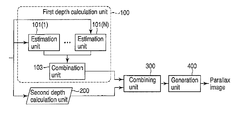
- FIG. 1A is a block diagram illustrating the parallax image generating apparatus of the first embodiment.
- the parallax image generating apparatus comprises a first depth calculation unit 100 , a second depth calculation unit 200 , a combining unit 300 , and a generation unit 400 .
- depth mean perceivable depth, unevenness, etc.
- the first depth calculation unit 100 includes N ( ⁇ 2) or more estimation units 101 ( 1 ) to 101 (N), and a combination unit 103 .
- the estimation units 101 ( 1 ) to 101 (N) estimate, using different methods, distributions of depths in a three-dimensional reproduction range defined by a front plane and a rear plane, the depths in the reproduction range corresponding to those in the first image. After that, the estimation units output data items indicating the estimated distributions.
- the combination unit 103 combines the data items to generate first depth information.
- the second depth calculation unit 200 calculates second depth information indicating relative unevenness in an object area in the first image.
- the object area is the area of the first image that includes an object.
- the distribution information indicates absolute depths in the depth reproduction range of the entire image, while the unevenness information indicates relative depths in the object. Namely, the depth range reproduced based on the distribution information is any part of the reproduction range, whereas the depth range reproduced based on the unevenness information is narrower than the reproduction range.
- the combining unit 300 combines the first and second depth information items to generate third depth information.
- the combining unit 300 combines the depth information using a method different from that of the combination unit 103 . This will be described later in detail.
- the generation unit 400 generates a parallax image based on the third depth information and the first image. Any known technique may be used to generate a parallax image from depth information.
- FIG. 1B shows a modification of the parallax image generating apparatus of the first embodiment. This modification differs from the first embodiment shown in FIG. 1A in that in the former, the second depth calculation unit 200 comprises M ( ⁇ 2) or more estimation units 201 ( 1 ) to 201 (M), and a combination unit 203 .
- the estimation unit 201 ( m ) (1 ⁇ m ⁇ M) detects a target object in a first image, estimates unevenness corresponding to the type of the detected object, and outputs unevenness information indicating the estimated unevenness. Further, the estimation units 201 ( 1 ) to 201 (M) may detect the same object by M different methods, and acquire unevenness information items related to the detection results by the same estimation method. Alternatively, the estimation units 201 ( 1 ) to 201 (M) may detect the same object by the same method, and acquire unevenness information items related to the detection result by M different methods.
- the combination unit 203 combines the unevenness information items output from the estimation units 201 ( 1 ) to 201 (M).
- FIG. 2 shows the operation of the parallax image generating apparatus of the first embodiment.
- the perceivable front position and the perceivable rear(most) position will hereinafter be referred to simply as “the front position” and “the rear(most) position,” respectively.
- the estimation units 101 ( 1 ) to 101 (N) acquire, by estimation using different methods, respective depth distribution information items corresponding to a depth distribution in a first image in the three-dimensional reproduction range (S 21 ( 1 )-(N)).
- the estimation unit 101 ( n ) acquires depth distribution information by estimation (1 ⁇ n ⁇ N).
- a method of preparing preset depth models and appropriately using them in accordance with the first image may be employed.
- FIG. 3A shows a model of depth distribution information.
- the x- and y-axes indicate the position in an image
- the white area indicates the rearmost area (which defines the rear plane of a reproduction range)
- the darker areas indicate the areas closer to the front plane (i.e., perceivable front plane).
- a method may be employed, in which motion between a first image and a second image to be displayed at a time different from the display time of the first image is detected, and a depth distribution is estimated based on the detected motion.
- a method of estimating a depth distribution in accordance with a particular pixel value pattern may be employed.
- step 21 ( n ) may employ any type of estimation method, if the method can acquire depth distribution information concerning the entire first image.
- the depth Z n at a pixel position (x, y) in the distribution information obtained at the n th step S 21 ( n ) (1 ⁇ n ⁇ N) is defined as described below. Note that 0 ⁇ Z n (x, y) ⁇ Z.
- the combination unit 103 combines a plurality of distribution information items acquired by the estimation units 101 ( 1 ) to 101 (N) to form first depth information (S 22 ).
- N depth information items are combined to generate a single first depth information item.
- the first depth information may be obtained by averaging the N depth information items, although this is not preferable to ray trace.
- the estimation units 201 ( 1 ) to 201 (M) detect target objects in the first image, and acquire, by estimation, uneven information items corresponding to the types of the detected objects (S 23 ( 1 )-S 23 (M)).
- the estimation unit 201 ( m ) estimates unevenness (1 ⁇ m ⁇ M). More specifically, each estimation units 201 detects a target object in the first image, and allocates, to the area of the detected object, an unevenness model preset in accordance with the type of the object, thereby calculating second depth information.
- a description will be given of a method of detecting the position and size of a face existing in the first image, and allocating a preset relative depth model to the detected position. By this, appropriate unevenness can be set in the object area.
- FIG. 3B shows an example of a model.
- the model is formed of the face and upper body of a person.
- the x- and y-axes indicate the position in the image.
- the white area indicates the rearmost area, and the darker areas indicate the areas closer to the front plane.
- Other objects may be detected as well as the face, and depth models corresponding thereto be assigned.
- the object to be detected is not limited to the face, but may be the entire body of a person, an animal, a vehicle, etc. In the first embodiment, a description will be given of the detection of a vehicle as well as the face.
- the unevenness information corresponding to the pixel position (x, y) and acquired by estimation at step S 23 ( m ) is defined as follows: Assume that ⁇ Z r ⁇ r m (x, y) ⁇ Z r , where r m (x, y) indicates the state in which there is no unevenness, ⁇ Z r indicates a relatively forward projecting state in the object area, and Z r indicates a relatively rearward projecting state in the object area.
- Z r can be determined based on the size of the detected object. For example, if the object is larger, the relative depth appears to be greater, and hence Z r is set larger. In contrast, if the object is smaller, Z r is set smaller. Further, Z r may be determined based on the first depth information corresponding to the position of the object. In this case, if the first depth information indicates the front position, Z r is set larger, whereas if it indicates the rear position, Z r is set smaller.
- the combination unit 203 combines the unevenness information items generated by the estimation units 201 ( 1 ) to 201 (M) to generate second depth information (S 24 ).
- second depth information In the computer graphics, to combine two depths, those near the camera are selected and combined. This is based on the ray trace idea, namely, based on the principle that the light entering the eyes is the light that was not interrupted.
- the second depth information may be obtained by averaging the M unevenness information items, although this is not preferable to ray trace.
- unevenness information items may be combined based on the first depth information. Assuming that the first depth information items at the centers of gravity of the objects that provide the unevenness information items are gravity-center depth information items, unevenness information at which gravity-center depth information corresponding to a position closest to the front plane is obtained may be selected as the unevenness information obtained at a position included in the area in which objects (e.g., a man and a vehicle) overlap each other.
- objects e.g., a man and a vehicle
- the combining unit 300 combines the first and second depth information items to generate third depth information (S 24 ). For combination, the combining unit 300 uses a method different from those of the combination units 103 and 203 .
- the first and second depth information items are summed up to generate the third depth information.
- zf ( x,y ) zc ( x,y )+ rc ( x,y ) where zf (x, y) indicates third depth information at a pixel position (x, y).
- the result of the combination of the first and second depth information items will depart from the desired depth reproduction range of 0 ⁇ z ⁇ Z in the three-dimensional space.
- the generation unit 400 Based on the third depth information and the first image, the generation unit 400 generates a parallax image (S 25 ). Firstly, a parallax vector is calculated from the third depth information. A detailed description will now be given of a method example of generating the parallax image.
- FIG. 4 is a view useful in explaining a method of calculating a parallax vector from depth information.
- the parallax vector can be calculated using the similarity between a triangle connecting the right and left eyes and an object to each other, and a triangle connecting the right and left parallaxes and the object to each other.
- the final depth information is indicated by zf
- the dimension of the parallax vector is indicated by d [cm].
- the distance between the eyes, the distance to the screen, the distance between the screen and the front position in the real space, and the depth in the real space are indicated by b [cm], z s [cm], z 0 [cm], and L z [cm], respectively.
- d pixel (screen resolution[pixel]/screen size[cm]) ⁇ d [cm]
- the depth information zf indicates the range of 0 to Z (the range of 0 to 1 may be used), 0 indicating the front position, Z indicating the rearmost position.
- these values are tentative ones, and must be converted into real distances.
- z′ ⁇ zf ⁇ z 0
- the above depth transform model is inversely proportional to the parallax vector.
- a function model may be employed in which, for example, part of the inversely proportional relationship is approximated by a proportional relationship.
- the above parameters b, z s , z 0 and L z for stereoscopic vision can be arbitrarily determined in accordance with a stereoscopic vision to provide. For instance, z s is determined based on the actual position of the screen, and z 0 is set greater if the degree of protrusion is to be increased. Further, the depth can be determined from L z .
- FIG. 5 is a view useful in explaining a method of generating a parallax image from the calculated parallax image.
- the right parallax image and the left parallax image can be generated from parallax vectors d L and d R obtained by multiplying the parallax vector d by ⁇ 1 ⁇ 2 and 1 ⁇ 2, respectively.
- d L ( ⁇ 1 ⁇ 2)
- d d R (1 ⁇ 2) d
- the left parallax image can be generated by moving the pixel values I t (x, y) of the first image in accordance with d L .
- the right parallax image can be generated by moving the pixel values I t (x, y) of the first image in accordance with d R .
- an area hereinafter referred to as a hole
- peripheral pixel values for example, are assigned.
- the third depth information employed in the parallax image generating apparatus of the first embodiment will be described.
- an image of a room and a person therein is the first image.
- a plurality of depth distributions are estimated by, for example, assigning the depths of the room to a model, or acquiring motion vectors, and combining the estimated distributions to generate first depth information.
- unevenness information (second depth information) is acquired by estimation by detecting the person in the first image.
- the thus-obtained first and second depth information items must be combined.
- the reproduction range of the unevenness information is extremely narrower than that of the depth distribution information of the entire image. Accordingly, if the first and second depth information items are combined by the same method as that for acquiring the first and/or second depth information, the unevenness of the object (person) cannot be sufficiently expressed, with the stereoscopic effect of the depth distributions kept in the image.
- the horizontal axis indicates the pixel position
- the vertical axis indicates the depth information
- FIGS. 6A and 6B show examples of depth information.
- FIG. 6A shows test patterns of the depth information.
- “0” indicates the rearmost position and “10” indicates the front position. Between this depth information and the above-mentioned one, the magnitude relation between the front position and the rearmost position is inverted.
- Distribution information 1 and distribution information 2 indicate examples generated by the estimation units 101 ( n ), and unevenness information 1 and unevenness information 2 indicate examples generated by the estimation units 201 ( m ).
- FIG. 6B shows the average information of the distribution information items 1 and 2 and the unevenness information items 1 and 2 , and the information obtained by selecting maximum values at respective positions in the test patterns of FIG. 6A , and combining them.
- the average information the depth dynamic range indicated by the distribution information items is compressed, and therefore the unevenness information is concealed.
- the latter information the depth distribution of the face is completely concealed, although the depth dynamic range of the entire room is kept. This is because the absolute depth distribution information on the entire image and the relative unevenness information on the object (face) are combined together.
- absolute depth means the absolute depth with reference to the depth reproduction range of 0 ⁇ z ⁇ Z
- relative means the relative depth in a local object area included in the entire image.
- the reproduction range of the relative depth information differs from that of the absolute depth information. Namely, the values of the absolute depth information differ in technical meaning from those of the relative depth information. Accordingly, if the absolute depth information and the relative depth information are combined by the same method, the resultant combination values do not sufficiently reflect the details of the image.
- FIG. 7A shows first depth information obtained by combining the distribution information items 1 and 2 shown in FIG. 6A .
- FIG. 7B shows second depth information obtained by combination based on the distribution information items 1 and 2 shown in FIG. 6A .
- a method of selecting information on the depth closest to the front plane at the same horizontal position was employed.
- FIG. 8 shows third depth information obtained by combining the first and second depth information items shown in FIGS. 7A and 7B . Actually, the first and second depth information items are added.
- a parallax image can be generated in which the unevenness of an object included in an image is sufficiently expressed while keeping the stereoscopic effect resulting from the depth distribution in the image.
- FIG. 9 shows a parallax image generating apparatus according to a second embodiment.
- the parallax image generating apparatus of the second embodiment differs from that shown in FIG. 1B in that the former has a function of adjusting depth information.
- Adjusting units 102 ( n ) adjust the respective distribution information items generated by the estimation units 101 ( n ). For instance, when the estimation unit 101 ( 1 ) outputs depth information in the range of 0 ⁇ z ⁇ Z, and the estimation unit 101 ( 2 ) outputs depth information in the range of 100 ⁇ z ⁇ Z, it is necessary to adjust the output range to the same range. To this end, the adjusting units 102 ( n ) adjust the different depth ranges to a certain range by, for example, fixing a point (hereinafter, a fixed point) (at, for example, Z) and broadening or narrowing the depth ranges. Further, if a certain estimation unit 101 ( n ) has a low reliability, its depth range is narrowed to the rear side to reduce the influence of depth information of low reliability.
- a fixed point at, for example, Z
- Adjusting units 202 ( m ) adjust the respective second depth information items generated by the estimation units 201 ( m ).
- the adjusting units 202 ( m ) may employ the same adjusting methods as those the adjusting units 102 ( n ). If the fixed point is set at 0, the characteristic of the relative unevenness information can be effectively utilized.
Landscapes
- Engineering & Computer Science (AREA)
- Multimedia (AREA)
- Signal Processing (AREA)
- Physics & Mathematics (AREA)
- General Physics & Mathematics (AREA)
- Theoretical Computer Science (AREA)
- Processing Or Creating Images (AREA)
- Testing, Inspecting, Measuring Of Stereoscopic Televisions And Televisions (AREA)
- Image Processing (AREA)
Abstract
Description
zc(x,y)=min{z 1(x,y), . . . , z N(x,y)}
where zc (x, y) indicates first depth information at a pixel position (x, y), and min {a, b, c . . . } indicates the operation of selecting the minimum value from {a, b, c . . . }. Alternatively, the first depth information may be obtained by averaging the N depth information items, although this is not preferable to ray trace.
r c(x,y)=min{r 1(x,y), . . . , r M(x,y)}
where rc (x, y) indicates second depth information at a pixel position (x, y). Alternatively, the second depth information may be obtained by averaging the M unevenness information items, although this is not preferable to ray trace.
zf(x,y)=zc(x,y)+rc(x,y)
where zf (x, y) indicates third depth information at a pixel position (x, y). Further, multiplication may be executed instead of addition (zf (x, y)=zc (x, y)·rc (x, y)).
d pixel=(screen resolution[pixel]/screen size[cm])·d[cm]
γ=L z /z max[cm]
where zmax=Z. In this case, the distance z′ between the screen and the object is given by
z′=γzf−z 0
d:b=(z′):(z s +z′) (1)
d(z s +z′)=bz′ (2)
z={(b−d)z 0 +dz s}/{γ(b−d)} (3)
d:b=(z′):(z s +z′)
d=b{z′/(z s +z′)}
d L=(−½)d
d R=(½)d
Claims (9)
Priority Applications (1)
| Application Number | Priority Date | Filing Date | Title |
|---|---|---|---|
| PCT/US2011/052860 WO2012040526A2 (en) | 2010-09-23 | 2011-09-23 | Multi-purpose cable support having bendable stem |
Applications Claiming Priority (2)
| Application Number | Priority Date | Filing Date | Title |
|---|---|---|---|
| JP2010-084326 | 2010-03-31 | ||
| JP2010084326A JP5227993B2 (en) | 2010-03-31 | 2010-03-31 | Parallax image generation apparatus and method thereof |
Publications (2)
| Publication Number | Publication Date |
|---|---|
| US20110242280A1 US20110242280A1 (en) | 2011-10-06 |
| US8665319B2 true US8665319B2 (en) | 2014-03-04 |
Family
ID=44697882
Family Applications (1)
| Application Number | Title | Priority Date | Filing Date |
|---|---|---|---|
| US12/888,582 Expired - Fee Related US8665319B2 (en) | 2010-03-31 | 2010-09-23 | Parallax image generating apparatus and method |
Country Status (3)
| Country | Link |
|---|---|
| US (1) | US8665319B2 (en) |
| JP (1) | JP5227993B2 (en) |
| CN (1) | CN102209248B (en) |
Cited By (1)
| Publication number | Priority date | Publication date | Assignee | Title |
|---|---|---|---|---|
| US20120236114A1 (en) * | 2011-03-18 | 2012-09-20 | Te-Hao Chang | Depth information generator for generating depth information output by only processing part of received images having different views, and related depth information generating method and depth adjusting apparatus thereof |
Families Citing this family (8)
| Publication number | Priority date | Publication date | Assignee | Title |
|---|---|---|---|---|
| JP5050094B2 (en) * | 2010-12-21 | 2012-10-17 | 株式会社東芝 | Video processing apparatus and video processing method |
| JP5303692B1 (en) | 2011-11-28 | 2013-10-02 | パナソニック株式会社 | Stereoscopic image processing apparatus and stereoscopic image processing method |
| JP6024110B2 (en) * | 2012-01-26 | 2016-11-09 | ソニー株式会社 | Image processing apparatus, image processing method, program, terminal device, and image processing system |
| EP2627093A3 (en) * | 2012-02-13 | 2013-10-02 | Thomson Licensing | Method and device for inserting a 3D graphics animation in a 3D stereo content |
| CN103577790B (en) * | 2012-07-26 | 2016-06-01 | 株式会社理光 | road turn type detection method and device |
| US9098911B2 (en) * | 2012-11-01 | 2015-08-04 | Google Inc. | Depth map generation from a monoscopic image based on combined depth cues |
| CN104935910B (en) * | 2015-06-03 | 2017-10-17 | 青岛海信电器股份有限公司 | A kind of method and apparatus of 3-D view correction |
| US11881694B2 (en) | 2021-04-19 | 2024-01-23 | Erico International Corporation | Data cable support |
Citations (16)
| Publication number | Priority date | Publication date | Assignee | Title |
|---|---|---|---|---|
| JP2001320731A (en) * | 1999-11-26 | 2001-11-16 | Sanyo Electric Co Ltd | Device for converting two-dimensional image into there dimensional image and its method |
| US6445833B1 (en) * | 1996-07-18 | 2002-09-03 | Sanyo Electric Co., Ltd | Device and method for converting two-dimensional video into three-dimensional video |
| US6590573B1 (en) * | 1983-05-09 | 2003-07-08 | David Michael Geshwind | Interactive computer system for creating three-dimensional image information and for converting two-dimensional image information for three-dimensional display systems |
| JP2004102689A (en) | 2002-09-10 | 2004-04-02 | Toppan Printing Co Ltd | Display control device |
| JP2005151534A (en) | 2003-09-24 | 2005-06-09 | Victor Co Of Japan Ltd | Pseudo three-dimensional image creation device and method, and pseudo three-dimensional image display system |
| US6940473B2 (en) * | 1998-05-21 | 2005-09-06 | Nippon Telegraph And Telephone Corporation | Three-dimensional representation method and an apparatus thereof |
| US20050219239A1 (en) * | 2004-03-31 | 2005-10-06 | Sanyo Electric Co., Ltd. | Method and apparatus for processing three-dimensional images |
| US20050253924A1 (en) * | 2004-05-13 | 2005-11-17 | Ken Mashitani | Method and apparatus for processing three-dimensional images |
| US20060050383A1 (en) * | 2003-01-20 | 2006-03-09 | Sanyo Electric Co., Ltd | Three-dimentional video providing method and three dimentional video display device |
| US20060066718A1 (en) * | 2004-09-29 | 2006-03-30 | Shingo Yanagawa | Apparatus and method for generating parallax image |
| JP2007219765A (en) | 2006-02-15 | 2007-08-30 | Toyota Motor Corp | Image processor, method therefor, and imaging processing program |
| US20070216975A1 (en) * | 2004-01-13 | 2007-09-20 | Holmes Brian W | Security Device |
| JP2007299070A (en) | 2006-04-27 | 2007-11-15 | Toshiba Corp | Face shape model generation apparatus and method |
| US20080225113A1 (en) * | 2007-03-15 | 2008-09-18 | Kabushiki Kaisha Toshiba | Three-dimensional image display device, method for displaying three-dimensional image, and structure of three-dimensional image data |
| US20090027571A1 (en) * | 2006-02-28 | 2009-01-29 | Brother Kogyo Kabushiki Kaisha | Image display device |
| CN101640809A (en) | 2009-08-17 | 2010-02-03 | 浙江大学 | Depth extraction method of merging motion information and geometric information |
-
2010
- 2010-03-31 JP JP2010084326A patent/JP5227993B2/en not_active Expired - Fee Related
- 2010-09-23 US US12/888,582 patent/US8665319B2/en not_active Expired - Fee Related
- 2010-11-30 CN CN201010567069.4A patent/CN102209248B/en not_active Expired - Fee Related
Patent Citations (17)
| Publication number | Priority date | Publication date | Assignee | Title |
|---|---|---|---|---|
| US6590573B1 (en) * | 1983-05-09 | 2003-07-08 | David Michael Geshwind | Interactive computer system for creating three-dimensional image information and for converting two-dimensional image information for three-dimensional display systems |
| US6445833B1 (en) * | 1996-07-18 | 2002-09-03 | Sanyo Electric Co., Ltd | Device and method for converting two-dimensional video into three-dimensional video |
| US6940473B2 (en) * | 1998-05-21 | 2005-09-06 | Nippon Telegraph And Telephone Corporation | Three-dimensional representation method and an apparatus thereof |
| JP2001320731A (en) * | 1999-11-26 | 2001-11-16 | Sanyo Electric Co Ltd | Device for converting two-dimensional image into there dimensional image and its method |
| JP2004102689A (en) | 2002-09-10 | 2004-04-02 | Toppan Printing Co Ltd | Display control device |
| US20060050383A1 (en) * | 2003-01-20 | 2006-03-09 | Sanyo Electric Co., Ltd | Three-dimentional video providing method and three dimentional video display device |
| US7403201B2 (en) * | 2003-01-20 | 2008-07-22 | Sanyo Electric Co., Ltd. | Three-dimensional video providing method and three-dimensional video display device |
| JP2005151534A (en) | 2003-09-24 | 2005-06-09 | Victor Co Of Japan Ltd | Pseudo three-dimensional image creation device and method, and pseudo three-dimensional image display system |
| US20070216975A1 (en) * | 2004-01-13 | 2007-09-20 | Holmes Brian W | Security Device |
| US20050219239A1 (en) * | 2004-03-31 | 2005-10-06 | Sanyo Electric Co., Ltd. | Method and apparatus for processing three-dimensional images |
| US20050253924A1 (en) * | 2004-05-13 | 2005-11-17 | Ken Mashitani | Method and apparatus for processing three-dimensional images |
| US20060066718A1 (en) * | 2004-09-29 | 2006-03-30 | Shingo Yanagawa | Apparatus and method for generating parallax image |
| JP2007219765A (en) | 2006-02-15 | 2007-08-30 | Toyota Motor Corp | Image processor, method therefor, and imaging processing program |
| US20090027571A1 (en) * | 2006-02-28 | 2009-01-29 | Brother Kogyo Kabushiki Kaisha | Image display device |
| JP2007299070A (en) | 2006-04-27 | 2007-11-15 | Toshiba Corp | Face shape model generation apparatus and method |
| US20080225113A1 (en) * | 2007-03-15 | 2008-09-18 | Kabushiki Kaisha Toshiba | Three-dimensional image display device, method for displaying three-dimensional image, and structure of three-dimensional image data |
| CN101640809A (en) | 2009-08-17 | 2010-02-03 | 浙江大学 | Depth extraction method of merging motion information and geometric information |
Non-Patent Citations (6)
| Title |
|---|
| Cheng, C. C. et al., "A Quality-Scalable Depth-Aware Video Processing System," 11.4, SID 09 Digest, pp. 123-126, (2009). |
| Final Office Action mailed by the Japanese Patent Office on May 24, 2012, in Japanese Application No. 2011-024192, 1 page. |
| First Office Action mailed by the Japanese Patent Office on Dec. 28, 2011, in the corresponding Japanese Application No. 2010-084326, 2 pages. |
| First Office Action mailed by the Japanese Patent Office on Mar. 7, 2012, in Japanese Application No. 2011-024192, 2 pages. |
| Notice of Reasons for Rejection issued by the Japanese Patent Office in Japanese Patent Application No. 2010-084326, mailed Dec. 28, 2011 (5 pages). |
| Second Office Action mailed by the Chinese Patent Office on Oct. 25, 2013, in counterpart Chinese Application No. CN201010567069.4; (19 pgs.) and English translation thereof. |
Cited By (1)
| Publication number | Priority date | Publication date | Assignee | Title |
|---|---|---|---|---|
| US20120236114A1 (en) * | 2011-03-18 | 2012-09-20 | Te-Hao Chang | Depth information generator for generating depth information output by only processing part of received images having different views, and related depth information generating method and depth adjusting apparatus thereof |
Also Published As
| Publication number | Publication date |
|---|---|
| CN102209248A (en) | 2011-10-05 |
| JP5227993B2 (en) | 2013-07-03 |
| US20110242280A1 (en) | 2011-10-06 |
| CN102209248B (en) | 2014-12-10 |
| JP2011215949A (en) | 2011-10-27 |
Similar Documents
| Publication | Publication Date | Title |
|---|---|---|
| US8665319B2 (en) | Parallax image generating apparatus and method | |
| US10701332B2 (en) | Image processing apparatus, image processing method, image processing system, and storage medium | |
| US9123115B2 (en) | Depth estimation based on global motion and optical flow | |
| US10229483B2 (en) | Image processing apparatus and image processing method for setting an illumination environment | |
| US9171372B2 (en) | Depth estimation based on global motion | |
| EP3841554A1 (en) | Method and system for reconstructing colour and depth information of a scene | |
| EP2848002B1 (en) | Apparatus and method for processing 3d information | |
| CN102510506B (en) | Virtual and real occlusion handling method based on binocular image and range information | |
| US20130038606A1 (en) | Image processing apparatus, image processing method, and program | |
| US9747690B2 (en) | Image processing device, image processing method, and program | |
| KR20160010120A (en) | Stereo matching apparatus and method using unary confidences learning and pairwise confidences learning | |
| JP2013003848A (en) | Virtual object display device | |
| US20160245641A1 (en) | Projection transformations for depth estimation | |
| US20210312647A1 (en) | Detecting device, information processing device, detecting method, and information processing program | |
| US20220148207A1 (en) | Processing of depth maps for images | |
| Afzal et al. | Rgb-d multi-view system calibration for full 3d scene reconstruction | |
| US8908994B2 (en) | 2D to 3d image conversion | |
| CN110678905B (en) | Apparatus and method for processing depth map | |
| US9282317B2 (en) | Method and apparatus for processing an image and generating information representing the degree of stereoscopic effects | |
| Toth et al. | Perception of highlight disparity at a distance in consumer head-mounted displays | |
| JP5087684B2 (en) | Image processing apparatus, image processing method, and image display apparatus | |
| CN116569214A (en) | Apparatus and method for processing depth map | |
| KR20130057147A (en) | Method and system for measuring a stability of three-dimensional image | |
| US20240073537A1 (en) | Information processing device, information processing method, and program | |
| JP6056459B2 (en) | Depth estimation data generation apparatus, pseudo stereoscopic image generation apparatus, depth estimation data generation method, and depth estimation data generation program |
Legal Events
| Date | Code | Title | Description |
|---|---|---|---|
| AS | Assignment |
Owner name: KABUSHIKI KAISHA TOSHIBA, JAPAN Free format text: ASSIGNMENT OF ASSIGNORS INTEREST;ASSIGNORS:MISHIMA, NAO;MITA, TAKESHI;SHIMOYAMA, KENICHI;AND OTHERS;REEL/FRAME:025442/0300 Effective date: 20100927 |
|
| FEPP | Fee payment procedure |
Free format text: PAYOR NUMBER ASSIGNED (ORIGINAL EVENT CODE: ASPN); ENTITY STATUS OF PATENT OWNER: LARGE ENTITY |
|
| FEPP | Fee payment procedure |
Free format text: MAINTENANCE FEE REMINDER MAILED (ORIGINAL EVENT CODE: REM.) |
|
| LAPS | Lapse for failure to pay maintenance fees |
Free format text: PATENT EXPIRED FOR FAILURE TO PAY MAINTENANCE FEES (ORIGINAL EVENT CODE: EXP.) |
|
| STCH | Information on status: patent discontinuation |
Free format text: PATENT EXPIRED DUE TO NONPAYMENT OF MAINTENANCE FEES UNDER 37 CFR 1.362 |
|
| FP | Lapsed due to failure to pay maintenance fee |
Effective date: 20180304 |