US8649507B2 - Mobile communications device enclosure - Google Patents
Mobile communications device enclosure Download PDFInfo
- Publication number
- US8649507B2 US8649507B2 US12/726,312 US72631210A US8649507B2 US 8649507 B2 US8649507 B2 US 8649507B2 US 72631210 A US72631210 A US 72631210A US 8649507 B2 US8649507 B2 US 8649507B2
- Authority
- US
- United States
- Prior art keywords
- tab
- mobile communications
- ejection
- communications device
- protection
- Prior art date
- Legal status (The legal status is an assumption and is not a legal conclusion. Google has not performed a legal analysis and makes no representation as to the accuracy of the status listed.)
- Expired - Fee Related, expires
Links
Images


Classifications
-
- H—ELECTRICITY
- H04—ELECTRIC COMMUNICATION TECHNIQUE
- H04B—TRANSMISSION
- H04B1/00—Details of transmission systems, not covered by a single one of groups H04B3/00 - H04B13/00; Details of transmission systems not characterised by the medium used for transmission
- H04B1/38—Transceivers, i.e. devices in which transmitter and receiver form a structural unit and in which at least one part is used for functions of transmitting and receiving
- H04B1/3827—Portable transceivers
- H04B1/3888—Arrangements for carrying or protecting transceivers
-
- Y—GENERAL TAGGING OF NEW TECHNOLOGICAL DEVELOPMENTS; GENERAL TAGGING OF CROSS-SECTIONAL TECHNOLOGIES SPANNING OVER SEVERAL SECTIONS OF THE IPC; TECHNICAL SUBJECTS COVERED BY FORMER USPC CROSS-REFERENCE ART COLLECTIONS [XRACs] AND DIGESTS
- Y10—TECHNICAL SUBJECTS COVERED BY FORMER USPC
- Y10T—TECHNICAL SUBJECTS COVERED BY FORMER US CLASSIFICATION
- Y10T29/00—Metal working
- Y10T29/49—Method of mechanical manufacture
- Y10T29/49826—Assembling or joining
Definitions
- This invention relates generally to portable device enclosures, and relates, more particularly, a case/enclosure for a portable media player or smartphone including apparatuses and related methods thereto.
- Smartphones can include one or more of the following features: the merging of a personal data/digital assistant (PDA) and a cellular phone; a keyboard interface (e.g., a QWERTY keyboard) configuration as either a touch screen or tactile keyboard; the capability to receive/download audio/video files.
- smartphones can: run an operating system software providing a standardized interface and platform for application developers; include advanced features like e-mail, Internet access and e-book reader capability; and/or (c) include a built-in full keyboard or external USB keyboard and VGA connector.
- a smartphone can be considered a miniature computer that has telephone capability.
- a smartphone is the iPhone® product by Apple Inc. of Cupertino, Calif.
- Another example of a smartphone is the Blackberry® product by Research In Motion (RIM) of Waterloo, Ontario, Canada.
- RIM Research In Motion
- controls e.g., buttons
- FIG. 1 is a perspective view illustrating an embodiment of an exemplary mobile media device case for providing protection of a mobile media device and allowing easier removal of the mobile media device from the mobile media device case, in accordance with the subject matter described herein;
- FIG. 2 is a rear view illustrating the mobile media device case of FIG. 1 , in accordance with the subject matter described herein;
- FIG. 3 is a front view illustrating the mobile media device case of FIG. 1 , in accordance with the subject matter described herein;
- FIG. 4 is a first side view illustrating the mobile media device case of FIG. 1 , in accordance with the subject matter described herein;
- FIG. 5 is a second side view illustrating the mobile media device case of FIG. 1 , in accordance with the subject matter described herein;
- FIG. 6 is a top view illustrating the mobile media device case of FIG. 1 , in accordance with the subject matter described herein;
- FIG. 7 is a bottom view illustrating the mobile media device case of FIG. 1 , in accordance with the subject matter described herein;
- FIG. 8 is a right, front three-quarter interior view of mobile media device case of FIG. 1 , in accordance with the subject matter described herein;
- FIG. 9 is a left, front three-quarter interior view illustrating the mobile media device case of FIG. 1 , in accordance with the subject matter described herein;
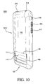
- FIG. 10 is a left, rear three-quarter exterior view illustrating the mobile media device case of FIG. 1 , in accordance with the subject matter described herein;
- FIG. 11 is a right, front three-quarter interior view illustrating the mobile media device case of FIG. 1 , in accordance with the subject matter described herein;
- FIG. 12 illustrates a left, front three-quarter interior view of mobile media device case of FIG. 1 and a mobile media device, in accordance with the subject matter described herein;
- FIG. 13 illustrates a flow chart of a method of manufacturing a mobile media device enclosure, in accordance with the subject matter described herein.
- Couple should be broadly understood and refer to connecting two or more elements or signals, electrically, mechanically or otherwise.
- Two or more electrical elements may be electrically coupled, but not mechanically or otherwise coupled; two or more mechanical elements may be mechanically coupled, but not electrically or otherwise coupled; two or more electrical elements may be mechanically coupled, but not electrically or otherwise coupled.
- Coupling (whether mechanical, electrical, or otherwise) may be for any length of time, e.g., permanent or semi-permanent or only for an instant.
- Electrode coupling and the like should be broadly understood and include coupling involving any electrical signal, whether a power signal, a data signal, and/or other types or combinations of electrical signals.
- Mechanical coupling and the like should be broadly understood and include mechanical coupling of all types. The absence of the word “removably,” “removable,” and the like near the word “coupled,” and the like does not mean that the coupling, etc. in question is or is not removable.
- a mobile media device enclosure can be configured to receive a mobile media device.
- the mobile media device enclosure can include: (a) a rigid portion, the rigid portion including a back wall and one or more sidewalls, the back wall and the one or more sidewalls defining an interior and an exterior of the mobile media device enclosure, the rigid portion configured to receive the mobile media device within the interior of the mobile media device enclosure; and (b) an ejection tab located at the back wall of the rigid portion, the ejection tab at least partially defined by a channel traversing from a first point in the rigid portion to a second point in the rigid portion, the ejection tab having a fixed portion and a moveable portion, the fixed portion of the ejection tab is mechanically coupled to the rigid portion, the movable portion of the ejection tab has a first portion mechanically coupled to the fixed portion of the ejection tab and a second portion at least partially defined by the channel.
- the movable portion of the ejection tab is configured to flexibly maintain a first position substantially parallel to an orientation of the back wall of the rigid portion, and the movable portion of the ejection tab is further configured to flexibly maintain a second position partially within the interior of the rigid portion when sufficient force is applied to the exterior of the rigid portion at the second portion of the movable portion of the ejection tab.
- a mobile media case system can be configured to enclose a mobile media device.
- the mobile media case system comprising a case having: (a) a rigid portion, the rigid portion of the case including a back wall and one or more sidewalls, the back wall and the one or more sidewalls defining an interior of the case and an exterior of the case, the rigid portion configured to enclose the mobile media device within the interior of the rigid portion; and (b) at least one protection tab, the at least one protection tab comprising a first portion substantially perpendicular to one of the one or more sidewalls and a second portion coupled to the first portion and the one of the one or more sidewalls, the second portion substantially parallel to the one of the one or more sidewalls.
- the one or more sidewalls have a user access area, and the user access area has an aperture.
- Each user access area is configured to provide user access to a portion of the mobile media device when the mobile media device is enclosed within the case.
- Each protection tab is associated with a user access area and mechanically coupled to the rigid portion. The at least one protection tab is further configured to overlie the aperture of the user access area of one of the one or more sidewalls.
- a method of manufacturing a mobile media device enclosure can include: providing at least one machine tool for at least partially creating the mobile media device enclosure; manufacturing the mobile media device enclosure using the at least one machine tool such that the mobile media device enclosure includes: a rigid case portion, the rigid case portion including a back wall and one or more sidewalls, the back wall and the one or more sidewalls defining an interior of the mobile media device enclosure and an exterior of the mobile media device enclosure, the rigid portion configured to receive a mobile media device within the interior of the mobile media device enclosure; and an ejection tab located at the back wall of the rigid portion, the ejection tab at least partially defined by a channel traversing from a first point in the rigid portion to a second point in the rigid portion, the ejection tab having a fixed portion and a moveable portion, the fixed portion of the ejection tab mechanically coupled to the rigid portion, and the movable portion of the ejection tab having a first portion mechanically coupled to the fixed portion of the ejection tab and a second portion at least
- FIG. 1 is a perspective view illustrating an embodiment of an exemplary mobile media device case 110 for providing protection of a mobile media device and allowing easier ejection of the mobile media device from mobile media device case 110 .
- FIG. 1 includes mobile media case system 100 that includes mobile media device case 110 configured to receive a mobile media device 1201 ( FIG. 12 ).
- mobile media device should be broadly understood and includes electrical devices of all types and designs (e.g., smartphones, media players, telephones, audio-visual media players, and devices incorporating media players, telephones, and/or audio-visual devices).
- Examples of mobile media devices include smartphones, cellular (or mobile) telephones, laptop computers, audio playback devices, AM (amplitude modulated) and FM (frequency modulated) radios, CD (compact disk) players, and media (e.g., MP3 (MPEG Audio Layer-3)) players.
- mobile media device case 110 can include rigid case portion 150 having: (a) back wall 151 ; (b) one or more sidewalls 152 , 153 , 154 , and 155 .
- Back wall 151 and sidewalls 152 , 153 , 154 , and 155 can define an interior 857 ( FIG. 8 ) and an exterior 158 of the mobile media device case 110 .
- Rigid case portion 150 can be configured to receive mobile media device 1201 ( FIG. 12 ) within the interior 857 ( FIG. 8 ).
- Mobile media device case 110 also can include ejection tab 115 .
- ejection tab 115 can be located in back wall 151 .
- ejection tab 115 at least partially defined by a channel 111 traversing from first point 112 to second point 113 .
- ejection tab 115 can be located in sidewall 152 , 153 , 154 , or 155 or in a combination of back wall 151 and one or more of sidewalls 152 , 153 , 154 and 155 .
- Mobile media device case 110 provides protection to a mobile media device encased within mobile media device case 110
- ejection tab 115 provides an improved method for removing the mobile media device from mobile media device case 110 .
- Mobile media device case 110 can additionally include hardware interface portion 120 and physical user input protection tabs 160 .
- Hardware interface portion 120 can be located in sidewall 155
- physical user input protection tabs 160 can be located in sidewall 152 .
- hardware interface portion 120 can be located in back wall 151 , and/or sidewalls 152 , 153 , or 154 .
- physical user input protection tabs 160 can be located in back wall 151 , and/or sidewalls 153 , 154 or 155 .
- Mobile media device case 110 can include elements not relevant to the present discussion.
- ejection tab 115 is integral with rigid case portion 150 such that ejection tab 115 and rigid case portion 150 have a unitary structure.
- physical user input protection tabs 160 are integral with rigid case portion 150 such that physical user input protection tabs 160 and rigid case portion 150 have a unitary structure.
- one or more of ejection tab 115 and physical user input protection tabs 160 can be separate from and/or separable from rigid case portion 150 .
- Ejection tab 115 is further detailed below.
- Physical user input protection tabs 160 are also detailed below.
- hardware interface portion 120 is a defined area or portion of sidewall 155 and/or back wall 151 that has been removed from mobile media device case 110 to allow a mobile media device enclosed within mobile media device case 110 to connect to an exterior device, such as, for example, a computing device. That is, hardware interface portion 120 has a hole 121 in sidewall 155 and/or back wall 151 .
- Hardware interface portion 120 can be configured to facilitate the mechanical and electrical coupling of a hardware interface cable connector with a hardware interface dock connector of the mobile media device.
- hardware interface portion 120 is configured as an area or portion removed from mobile media device case 110 to accommodate connecting the mobile media device enclosed within mobile media device case 110 to a proprietary or non-proprietary connector, such as, for example, a 30-pin connector designed to be used with an Apple® iPod® or iPhone® or iTouch® product.
- hardware interface portion 120 is configured to accommodate connecting to the mobile media device using a USB (universal serial bus) connector.
- Hardware interface portion 120 is further detailed below.
- Physical user input protection tabs 160 are located at one or more exemplary areas of rigid case portion 150 of mobile media device case 110 , where each of such areas includes one or more portions of mobile media device case 110 that have been modified to allow user access to physical user inputs on the mobile media device 1201 ( FIG. 12 ).
- physical user input protection tabs 160 are implemented as protection tabs (detailed below) associated with each physical user input location that provide protection and input access to each associated physical user input location.
- physical user input protection tabs 160 are implemented as protection tabs formed from material cut and modified from rigid case portion 150 and configured as one or more flat springy sheets, such as, in a leaf spring configuration. Furthermore, physical user input protection tabs 160 are configured such that each tab provides protection of the user input buttons located on the associated edges of the mobile media device enclosed within mobile media device case 110 below the tabs. In FIG. 1 , physical user input protection tabs 160 are further configured such that each tab, when depressed, makes contact with the associated user input buttons located on the associated edges of the mobile media device. User input protection tab 160 can be sized such that a surface area of each of user input protection tabs 160 is less than the surface area of the holes in rigid case portion 150 in which user input protection tabs 160 are located.
- Ejection tab 115 can be a portion of mobile media device case 110 and can include: (a) a fixed portion 141 ; and (b) a movable portion 142 . Movable portion 142 is separated from bottom portion 143 by channel 111 .
- Fixed portion 141 can be the portion of ejection tab 115 that can be coupled to rigid case portion 150 at back wall 151 .
- Movable portion 142 can be mechanically coupled to fixed portion 141 and configured to rotate or move about the coupling point of fixed portion 141 and rigid case portion 150 .
- Fixed portion 141 can be integral with movable portion 142 and back wall 151 .
- ejection tab 115 is located within the bottom half of mobile media device case 110 . In other embodiments, ejection tab 115 can be located within a different portion of mobile media device case 110 , including the top half or the middle portion.
- Movable portion 142 can be implemented as a semi-rigid (if not rigid) member that is configured to flexibly rotate about the coupling point of fixed portion 141 and rigid case portion 150 when a user applies sufficient force to move movable portion 142 using one or more prescribed methodologies (See FIG. 10 ).
- channel 111 can at least partially define ejection tab 115 .
- channel 111 defines three sides of the movable portion of ejection tab 115 with the fourth side (e.g., fixed portion 141 ) coupled to rigid case portion 150 .
- channel 111 can form an angular “U” shape.
- movable portion 142 can have an angular U-shape.
- channel 111 defines only two sides of the movable portion of ejection tab 115 , with the other side(s) defined by fixed portion ejection tab 115 .
- channel 111 has a rounded or curved shape without distinct “sides.”
- channel 111 has a curvilinear shape and movable portion 142 can include a single side with a curvilinear shape.
- Movable portion 142 is configured to flexibly maintain a first position substantially parallel to the orientation of back wall 151 . Movable portion 142 is further configured to flexibly maintain a second position partially within the interior of rigid case portion 150 when sufficient force is applied to the exterior of rigid case portion 150 at a second portion of movable portion 142 . Ejection tab 115 can be further configured so that the movable portion 142 returns to its original position (e.g., the first position) when the force applied to movable portion 142 is reduced or removed.
- a user applies force in a first direction F 1 within the area of ejection tab 115 while simultaneously applying additional force in a different direction at, for example, locations identified by F 2 and/or F 3 .
- the forces applied to the locations identified by F 2 and F 3 are each applied at different points on the exterior side of mobile media device case 110 proximate the corner or edges of mobile media device case 110 near hardware interface portion 120 .
- the direction of F 2 and F 3 are substantially opposite to direction F 1 .
- the direction of F 2 and F 3 are substantially parallel to each other or are otherwise in similar directions as illustrated in FIG. 1 .
- Mobile media device case 110 can be at least partially manufactured from any suitable material that is at least semi-rigid, including polycarbonate.
- rigid can mean rigid or semi-rigid.
- the thickness of ejection tab 115 and, in particular, the movable portion of ejection tab 115 is the same as the thickness of the remaining portions of mobile media device case 110 .
- the thickness of ejection tab 115 , or at least fixed portion 141 of ejection tab 115 is less than the thickness other portions of mobile media device case 110 to facilitate the movement of ejection tab 115 .
- FIG. 2 is a rear view illustrating the mobile media device case of FIG. 1 including a movable portion of an ejection tab.
- FIG. 2 shows a mobile media case system 200 that includes mobile media device case 210 .
- mobile media device case 210 includes rigid case portion 150 and ejection tab 115 .
- Mobile media device case 110 additionally includes channel 111 that defines ejection tab 115 .
- mobile media device case 210 additionally includes hardware interface portion 120 , physical user input protection tabs 160 , protection tab 213 , access area 214 and access area 216 .
- Elements similarly numbered with the last two significant digits and described in FIG. 1 function in a substantially similarly way.
- mobile media device case 210 may include elements not relevant to the present discussion.
- protection tab 213 can be located at sidewall 153 . Protection tab 213 can provide protection and user access to the main power control of a mobile media device 1201 ( FIG. 12 ) encased or enclosed within mobile media device case 210 . Protection tab 213 is further detailed below.
- access area 214 can also be located at sidewall 153 . Access area 214 can provide user access to an auxiliary connector, such as, for example an auxiliary input connector, or an auxiliary output connector of a mobile media device encased or enclosed within mobile media device case 110 . In the example illustrated in FIG. 2 , access area 214 can provide user access to an auxiliary output connector, such as a 3.5 mm speaker/input dual use connector.
- access area 216 can be located at sidewall 152 and can provide user access to a user activated switch, such as, for example a user activated “mute” switch to mute or un-mute a mobile media device encased or enclosed within mobile media device case 110 .
- a user activated switch such as, for example a user activated “mute” switch to mute or un-mute a mobile media device encased or enclosed within mobile media device case 110 .
- Protection tab 213 is located on a portion of rigid case portion 150 of mobile media device case 110 that has been modified to allow user access to physical user inputs on the mobile media device (not shown). In some embodiments, protection tab 213 is implemented as a protection tab (further detailed below) at a physical user input location. Protection tab 213 can provide protection and input access at the associated physical user input location.
- protection tab 213 can be implemented as a protection tab formed from material cut and modified from rigid case portion 150 and configured as a flat springy sheet, (e.g., a leaf spring configuration). Furthermore, protection tab 213 can be configured such that the tab provides protection of the user input button located on the associated edge of the enclosed mobile media device. Protection tab 213 can be further configured such that the tab, when depressed, makes contact with the associated user input button located on the associated edge of the mobile media device.
- Protection tab 213 can be associated with a user access area and mechanically coupled to rigid case portion 150 .
- protection tab 213 can include a first portion substantially perpendicular to sidewall 153 and a second portion coupled to the first portion and configured substantially parallel to the surface of sidewall 153 . Protection tab 213 can be further configured to overlie a hole in the user access area of sidewall 153 .
- FIG. 3 is a front view illustrating the mobile media device case 310 including movable portion 142 of ejection tab 115 .
- FIG. 3 shows a mobile media case system 300 that includes mobile media device case 310 .
- mobile media device case 310 includes rigid case portion 150 and ejection tab 115 .
- Mobile media device case 310 additionally includes channel 111 that at least partially defines ejection tab 115 .
- mobile media device case 310 additionally includes hardware interface portion 120 , physical user input protection tabs 160 , protection tab 213 , access area 214 and access area 216 .
- Elements similarly numbered with the last two significant digits and described in FIGS. 1 and 2 function in a substantially similarly way.
- mobile media device case 310 may include elements not relevant to the present discussion.
- FIG. 4 is a first side view illustrating sidewall 152 of mobile media device case 410 .
- FIG. 4 illustrates a right-side view of mobile media device case 110 of FIG. 1 .
- FIG. 4 shows a mobile media case system 400 that includes mobile media device case 410 .
- mobile media device case 410 includes rigid case portion 150 and ejection tab 115 .
- Mobile media device case 410 additionally includes channel 111 that at least partially defines ejection tab 115 .
- mobile media device case 410 additionally includes physical user input protection tabs 160 and protection tab 213 .
- Physical user input protection tabs 160 additionally includes protection tab 416 and protection tab 417 .
- Elements similarly numbered with the last two significant digits and described in FIGS. 1-3 function in a substantially similarly way.
- mobile media device case 410 may include elements not relevant to the present discussion.
- protection tab 416 and protection tab 417 are located at one or more exemplary areas of rigid case portion 150 of mobile media device case 110 , where each of such areas includes one or more portions of mobile media device case 110 that have been modified to allow user access to physical user inputs on the mobile media device (not shown).
- protection tab 416 and protection tab 417 are implemented as protection tabs associated with physical user input locations that provide protection and input access to each of the associated physical user input locations.
- protection tab 416 and protection tab 417 are implemented as protection tabs formed from material cut and modified from rigid case portion 150 and configured as one or more flat springy sheets, (e.g., a leaf spring configuration).
- protection tabs 416 and 417 provide protection and user access to user interface controls of a mobile media device encased within mobile media device case 410 .
- protection tab 416 and protection tab 417 are configured such that each tab provides protection of the user input buttons (e.g., volume up and volume down controls) located on the associated edges of the mobile media device.
- protection tabs 416 and 417 provide protection and user access to “up” and “down” user interface controls of an iPhone® device encased within mobile media device case 410 .
- protection tab 416 and protection tab 417 are further configured such that each tab, when depressed, makes contact with the associated user input button located on the associated edges of the mobile media device.
- FIG. 5 is a second side view illustrating side 154 of mobile media device case 510 .
- FIG. 5 illustrates a left-side view of mobile media device case 110 of FIG. 1 .
- FIG. 5 shows a mobile media case system 500 that includes mobile media device case 510 .
- mobile media device case 510 includes rigid case portion 150 and ejection tab 115 .
- Mobile media device case 510 additionally includes channel 111 that at least partially defines ejection tab 115 .
- Mobile media device case 510 further includes protection tab 213 .
- Elements similarly numbered with the last two significant digits and described in FIGS. 1-4 function in a substantially similarly way.
- mobile media device case 510 may include elements not relevant to the present discussion.
- FIG. 6 is a top view illustrating sidewall 153 of mobile media device case 610 with the front face and interior of mobile media device case 610 facing downwards.
- FIG. 6 shows a mobile media case system 600 that includes mobile media device case 610 .
- mobile media device case 610 includes rigid case portion 150 and an ejection tab (not shown in FIG. 6 ).
- Mobile media device case 610 additionally includes protection tab 213 , access area 214 , and protection tab 416 .
- Elements similarly numbered with the last two significant digits and described in FIGS. 1-5 function in a substantially similarly way.
- mobile media device case 610 may include elements not relevant to the present discussion.
- FIG. 7 is a bottom view illustrating sidewall 155 of mobile media device case 710 with the front face and interior of mobile media device case 710 facing upwards.
- FIG. 7 shows a mobile media case system 700 that includes mobile media device case 710 .
- mobile media device case 710 includes rigid case portion 150 and an ejection tab (not shown in FIG. 7 ).
- Mobile media device case 710 additionally includes hardware interface portion 120 , protection tab 213 , access area 214 , and protection tab 416 .
- Elements similarly numbered with the last two significant digits and described in FIGS. 1-6 function in a substantially similarly way.
- mobile media device case 710 may include elements not relevant to the present discussion.
- FIG. 8 is a right, front three-quarter interior view illustrating an interior 857 of mobile media device case 810 .
- FIG. 8 shows a mobile media case system 800 that includes mobile media device case 810 .
- mobile media device case 810 includes rigid case portion 150 and ejection tab 115 .
- Mobile media device case 810 additionally includes channel 111 that at least partially defines ejection tab 115 .
- mobile media device case 810 additionally includes hardware interface portion 120 , protection tab 213 , access area 214 , access area 216 , and protection tabs 416 and 417 .
- Elements similarly numbered with the last two significant digits and described in FIGS. 1-7 function in a substantially similarly way.
- mobile media device case 810 may include elements not relevant to the present discussion.
- interior 857 of mobile media device case 810 includes a softer material than the exterior portion of mobile media device case 810 to prevent mobile media device case 810 from scratching the rear surface of the enclosed mobile media device 1201 ( FIG. 12 ).
- the interior portion of mobile media device case 810 can include a urethane or other rubber layer or coating over the polycarbonate or other semi-rigid or rigid material used for the exterior portion.
- the interior portion can include a microfiber, linen, satin, or other fabric interior.
- only the interior portion of ejection tab 115 or movable portion 142 has the softer material.
- FIG. 9 is a left, front three-quarter interior view illustrating interior 857 of mobile media device case 910 .
- FIG. 9 shows a mobile media case system 900 that includes mobile media device case 910 .
- mobile media device case 910 includes rigid case portion 150 and ejection tab 115 .
- Mobile media device case 910 additionally includes channel 111 that at least partially defines ejection tab 115 .
- mobile media device case 910 additionally includes hardware interface portion 120 , protection tab 213 , access area 214 , access area 216 , and protection tabs 416 and 417 .
- Elements similarly numbered with the last two significant digits and described in FIGS. 1-8 function in a substantially similarly way.
- mobile media device case 910 may include elements not relevant to the present discussion.
- protection tab 416 includes first tab portion 961 and second tab portion 962
- protection tab 417 includes first tab portion 971 and second tab portion 972
- protection tab 213 also includes first and second portions, but such portions are not labeled.
- first tab portion 961 of protection tab 416 and first tab portion 971 of protection tab 417 are configured to be movable in physical communication with mobile media device case 910 .
- second tab portion 962 of protection tab 416 and second tab portion 972 of protection tab 417 have dimensions substantially similar to the associated removed portions or holes of media device case 910 .
- first tab portion 961 of protection tab 416 and first tab portion 971 of protection tab 417 are configured to protrude outwardly from mobile media device case 910 . When in use, they are configured (e.g., bent) to lie substantially parallel to and at a predetermined distance or gap from the associated removed portions of media device case 910 .
- second tab portion 962 of protection tab 416 and second tab portion 972 of protection tab 417 (as well as the second tab portion of protection tab 213 ) generally follow and substantially cover at a predetermined distance or gap from the associated removed portion (i.e., hole) of media device case 910 .
- First tab portion 961 of protection tab 416 and first tab portion 971 of protection tab 417 can be substantially analogous in functionality to ejection tab 115 , except that first tab portion 961 of protection tab 416 and first tab portion 971 of protection tab 417 (as well as the first tab portion of protection tab 213 ) are not flush with the surface of mobile media device case 910 .
- second tab portion 962 of protection tab 416 and second tab portion 972 of protection tab 417 (as well as the second tab portion of protection tab 213 ) can function analogously to fixed portion of ejection tab 115 .
- First tab portion 961 and/or second tab portion 962 of protection tab 416 and first tab portion 971 and/or second tab portion 972 of protection tab 417 can be positioned in a substantially curved manner (e.g. bent) when in a bent/stressed state.
- each of protection tabs 213 , 416 and 417 can be located usually in one of two positions.
- the second tab portion 962 and second tab portion 972 (as well as the second tab portion of protection tab 213 ) are not in contact with an associated physical user input in the first position.
- second tab portion 962 and second tab portion 972 (as well as the second tab portion of protection tab 213 ) are located a predetermined distance from the associated physical user input of a mobile media device enclosed within mobile media device case 910 .
- the first position can also be referred to as the relaxed position.
- first tab portions 961 and 971 are substantially perpendicular to sidewall 152 when in the relaxed state.
- second tab portions 962 and 972 are substantially parallel to sidewall 152 when in the relaxed state.
- the second position provides for the second tab portion 962 and second tab portion 972 (as well as the second tab portion of protection tab 213 ) can be in contact with an associated physical user input.
- the second tab portions can be placed in the second positions, when a user applies sufficient force to second tab portion 962 and second tab portion 972 (as well as the second tab portion or protection tab 213 ) to put the second tab portions in contact with an associated physical user input.
- the second position can be referred to as the stressed position, and in the second position, first tab portion 961 and first tab portion 971 (as well as the first tab portion of protection tab 213 ) can be bent or stressed while the second tab portion 962 and second tab portion 972 (as well as the second tab portion of protection tab 213 ) can be relaxed or bent/stressed.
- Protection tabs 213 , 416 and 417 can be formed simultaneously with media device case 910 during the manufacturing process. In another embodiment, protection tabs 213 , 416 and 417 are manufactured separately from the same or different materials and mechanically coupled to media device case 910 . In a further embodiment, mobile media device case 910 does not include one or more of protection tabs 213 , 416 , and 417 and, instead, has one or more holes where protection tabs 213 , 416 , and/or 417 would otherwise be located to allow access to the physical user input.
- FIG. 10 is a left-rear three-quarter exterior view illustrating the mobile media device case of FIG. 1 including the movable portion 142 of the ejection tab 115 in a device ejection position.
- FIG. 10 shows a mobile media case system 1000 that includes mobile media device case 1010 .
- mobile media device case 1010 includes rigid case portion 150 and ejection tab 115 .
- Mobile media device case 1010 additionally includes channel 111 that at least partially defines ejection tab 115 .
- mobile media device case 1010 additionally includes hardware interface portion 120 , protection tab 213 , access area 214 , access area 216 , and protection tabs 416 and 417 .
- Elements similarly numbered with the last two significant digits and described in FIGS. 1-9 function in a substantially similarly way.
- mobile media device case 1010 may include elements not relevant to the present discussion.
- ejection tab 115 includes a fixed portion 141 and a movable portion 142 that can be a semi-rigid (or rigid) member configured to flexibly rotate about fixed portion when a user applies sufficient force to the movable portion 142 using one or more methods.
- ejection tab 115 when sufficient force is applied to the movable portion 142 , ejection tab 115 will move about fixed portion 141 and displace a mobile media device 1201 ( FIG. 12 ) from within media device case 1010 .
- ejection tab 115 is shown to be rotated, moved, or deformed while a sufficient force is applied to the movable portion of ejection tab 115 .
- the configuration of media device case 1010 permits the removal of a media device 1201 ( FIG. 12 ) from media device case 1010 .
- FIG. 11 is a right-front three-quarter interior view illustrating the mobile media device case 1110 including the movable portion 142 of the ejection tab 115 in a device ejection position.
- FIG. 11 shows a mobile media case system 1100 that includes mobile media device case 1110 .
- mobile media device case 1110 includes rigid case portion 150 and ejection tab 115 .
- Mobile media device case 1110 additionally includes channel 111 that at least partially defines ejection tab 115 .
- mobile media device case 1110 additionally includes hardware interface portion 120 , protection tab 213 , access area 214 , access area 216 , and protection tabs 416 and 417 .
- Elements similarly numbered with the last two significant digits and described in FIGS. 1-10 function in a substantially similarly way.
- mobile media device case 1110 may include elements not relevant to the present discussion. Similar to FIG. 10 , FIG. 11 shows ejection tab 115 in a rotated, moved, or deformed state.
- FIG. 12 illustrates a left-front three-quarter interior view of mobile media device case 1210 and a mobile media device 1201 .
- FIG. 12 shows a mobile media case system 1200 that includes mobile media device case 1210 and a mobile media device 1201 .
- mobile media device case 1210 includes rigid case portion 150 and ejection tab 115 that can be physically part of mobile media device case 1210 .
- Mobile media device case 1210 additionally includes channel 111 that at least partially defines ejection tab 115 .
- mobile media device case 1210 additionally includes hardware interface portion 120 , protection tab 213 , access area 214 , access area 216 , and protection tabs 416 and 417 .
- Elements similarly numbered with the last two significant digits and described in FIGS. 1-11 function in a substantially similarly way.
- mobile media device case 1210 may include elements not relevant to the present discussion.
- mobile media case system 1200 illustrates one embodiment of mobile media device case 1210 and mobile media device 1201 in operation where mobile media device 1201 has just been removed or ejected from mobile media device case 1210 .
- mobile media device 1201 includes a rear surface facing towards the front and interior of mobile media device case 1210
- mobile media device 1201 includes a front surface facing away from mobile media device case 1210 .
- movable portion 142 of ejection tab 115 will rotate or move about fixed portion 141 of ejection tab 115 and displace mobile media device 1201 from within mobile media device case 1210 .
- FIG. 13 illustrates an example of a method 1300 of manufacturing a portable device according to embodiments.
- the activities of the method 1300 described in the flow chart of FIG. 13 can be performed in the order presented.
- the activities of the method 1300 described in the flow chart of FIG. 13 can be performed in any other suitable order.
- one or more of the activities of the method 1300 described in the flow chart of FIG. 13 can be combined.
- Method 1300 of FIG. 13 includes an activity 1310 of providing at least one machine tool for producing a mobile media device enclosure.
- the at least one machine tool is configured to produce a mobile media device enclosure having a rigid case portion and an ejection tab that is at least partially defined by a channel.
- the at least one machine tool is configured to produce mobile media device case 110 having rigid case portion 150 and ejection tab 115 defined by a channel 111 .
- the channel defines three sides (e.g., With an angular “U” shape) of the ejection tab with the fourth side (e.g., the fixed portion) coupled to the rigid case portion of the mobile media device case.
- the channel defines two sides of the movable portion of the ejection tab, with the other side(s) forming the fixed portion of the ejection tab and being coupled to the rigid case portion of the mobile media device case.
- the at least one machine tool is configured to produce a mobile media device enclosure having one or more user input protection tabs.
- the at least one machine tool is configured to remove a portion of material from a rigid case portion of the mobile media device case during the manufacturing step of activity 1320 .
- the at least one machine tool is configured so that material removed from the rigid case portion can include a portion that remains coupled to the rigid case portion of the mobile media device case.
- the at least one machine tool is configured so that the portion that remains coupled to the rigid case portion of the mobile media device case is configured outwardly from the mobile media device case and, then, are further configured (e.g., bent) to lie substantially parallel to and at a predetermined distance from the associated openings within the media device case.
- the at least one machine tool is configured to produce mobile media device case 910 having protection tabs 416 and 417 .
- the at least one machine tool is configured to remove a portion of material from rigid case portion 150 of mobile media device case 910 during the manufacturing process of activity 1320 .
- the at least one machine tool is configured so that first tab portion 961 remains coupled to rigid case portion 150 of the mobile media device case 910 .
- the at least one machine tool is configured so that first tab portion 961 is configured outwardly from mobile media device case 910 and, then, is further configured (e.g., bent) to include a second tab portion 962 that lays substantially parallel to and at a predetermined distance from the associated openings within media device case 910 .
- Method 1300 in FIG. 13 continues with an activity 1320 of manufacturing a mobile media device enclosure using the at least one machine tool.
- the at least one machine tool can include a machine tool that can injection mold a portable media device enclosure.
- the injection mold process can use polycarbonate or another material that can be hardened or made rigid or semi-rigid to create the portable media device enclosure.
- the at least one machine tool can also include machine tools to produce an ejection tab and/or one or more protection tabs. After removing the media device enclosure from the at least one machine tool, a softer material can be applied to one or more interior portions of the media device enclosure.
- Method 1300 in FIG. 13 continues with an activity 1330 distributing the mobile media device enclosure.
- distributing the mobile media device enclosure includes packaging and shipping one or more packaged mobile media device enclosures through a distribution channel. In other embodiments, distributing the mobile media device enclosure includes selling and shipping one or more mobile media device enclosures through a distribution channel.
- embodiments and limitations disclosed herein are not dedicated to the public under the doctrine of dedication if the embodiments and/or limitations: (1) are not expressly claimed in the claims; and (2) are or are potentially equivalents of express elements and/or limitations in the claims under the doctrine of equivalents.
Abstract
Description
Claims (26)
Priority Applications (1)
| Application Number | Priority Date | Filing Date | Title |
|---|---|---|---|
| US12/726,312 US8649507B2 (en) | 2009-03-17 | 2010-03-17 | Mobile communications device enclosure |
Applications Claiming Priority (2)
| Application Number | Priority Date | Filing Date | Title |
|---|---|---|---|
| US16080109P | 2009-03-17 | 2009-03-17 | |
| US12/726,312 US8649507B2 (en) | 2009-03-17 | 2010-03-17 | Mobile communications device enclosure |
Publications (2)
| Publication Number | Publication Date |
|---|---|
| US20100244638A1 US20100244638A1 (en) | 2010-09-30 |
| US8649507B2 true US8649507B2 (en) | 2014-02-11 |
Family
ID=42739983
Family Applications (1)
| Application Number | Title | Priority Date | Filing Date |
|---|---|---|---|
| US12/726,312 Expired - Fee Related US8649507B2 (en) | 2009-03-17 | 2010-03-17 | Mobile communications device enclosure |
Country Status (2)
| Country | Link |
|---|---|
| US (1) | US8649507B2 (en) |
| WO (1) | WO2010107959A1 (en) |
Cited By (1)
| Publication number | Priority date | Publication date | Assignee | Title |
|---|---|---|---|---|
| USD997944S1 (en) * | 2021-08-05 | 2023-09-05 | Cor Sanctum, LLC | Anti-eavesdropping device |
Families Citing this family (7)
| Publication number | Priority date | Publication date | Assignee | Title |
|---|---|---|---|---|
| WO2012058827A1 (en) | 2010-11-01 | 2012-05-10 | Su Yuanzhi | Fixing mechanism for flat panel display device |
| USD750056S1 (en) * | 2012-10-31 | 2016-02-23 | Chi Mei Communication Systems, Inc. | Combined card holder and cover for portable electronic device |
| USD823289S1 (en) * | 2014-09-05 | 2018-07-17 | Apple Inc. | Case for mobile communications device |
| CN105269753B (en) * | 2015-10-30 | 2017-07-14 | 广东拓斯达科技股份有限公司 | Plate positioning device in three-stage phone housing |
| USD928765S1 (en) * | 2020-02-04 | 2021-08-24 | Google Llc | Case for a mobile electronic communications device |
| USD926746S1 (en) * | 2020-02-04 | 2021-08-03 | Google Llc | Case for a mobile electronic communications device |
| USD948492S1 (en) | 2020-08-05 | 2022-04-12 | Apple Inc. | Case for an electronic device |
Citations (7)
| Publication number | Priority date | Publication date | Assignee | Title |
|---|---|---|---|---|
| US6176401B1 (en) | 1999-02-12 | 2001-01-23 | Motorola, Inc. | Holster for a portable communication device |
| US20020127370A1 (en) | 2000-03-10 | 2002-09-12 | Shaun Ruck | Injection moulding |
| US20030036362A1 (en) | 2001-08-20 | 2003-02-20 | Buesseler Joshua R. | Interchangeable cover for a mobile communications device |
| US20030068035A1 (en) | 2001-10-05 | 2003-04-10 | Jouko Pirila | User changeable electronic device/mobile phone covers and method |
| US6701159B1 (en) | 2000-03-03 | 2004-03-02 | Andew P. Powell | Jacket for cellular phone |
| US20070060224A1 (en) | 2005-09-14 | 2007-03-15 | Ming-Chin Liu | Mobile phone case |
| WO2009018345A2 (en) | 2007-07-30 | 2009-02-05 | Marware, Inc. | Mobile telephone case |
Family Cites Families (1)
| Publication number | Priority date | Publication date | Assignee | Title |
|---|---|---|---|---|
| EP1884512A4 (en) * | 2005-05-23 | 2011-09-28 | Sagami Chem Res | Pyrazole-1-carboxylic ester derivative, method for producing the same and method for producing pyrazole derivative |
-
2010
- 2010-03-17 US US12/726,312 patent/US8649507B2/en not_active Expired - Fee Related
- 2010-03-17 WO PCT/US2010/027733 patent/WO2010107959A1/en active Application Filing
Patent Citations (7)
| Publication number | Priority date | Publication date | Assignee | Title |
|---|---|---|---|---|
| US6176401B1 (en) | 1999-02-12 | 2001-01-23 | Motorola, Inc. | Holster for a portable communication device |
| US6701159B1 (en) | 2000-03-03 | 2004-03-02 | Andew P. Powell | Jacket for cellular phone |
| US20020127370A1 (en) | 2000-03-10 | 2002-09-12 | Shaun Ruck | Injection moulding |
| US20030036362A1 (en) | 2001-08-20 | 2003-02-20 | Buesseler Joshua R. | Interchangeable cover for a mobile communications device |
| US20030068035A1 (en) | 2001-10-05 | 2003-04-10 | Jouko Pirila | User changeable electronic device/mobile phone covers and method |
| US20070060224A1 (en) | 2005-09-14 | 2007-03-15 | Ming-Chin Liu | Mobile phone case |
| WO2009018345A2 (en) | 2007-07-30 | 2009-02-05 | Marware, Inc. | Mobile telephone case |
Non-Patent Citations (1)
| Title |
|---|
| PCT Search Report dated Jul. 7, 2010 for Application No. PCT/US2010/027733, 5 pages. |
Cited By (1)
| Publication number | Priority date | Publication date | Assignee | Title |
|---|---|---|---|---|
| USD997944S1 (en) * | 2021-08-05 | 2023-09-05 | Cor Sanctum, LLC | Anti-eavesdropping device |
Also Published As
| Publication number | Publication date |
|---|---|
| WO2010107959A1 (en) | 2010-09-23 |
| US20100244638A1 (en) | 2010-09-30 |
Similar Documents
| Publication | Publication Date | Title |
|---|---|---|
| US8452004B2 (en) | Multi-piece mobile media device enclosure | |
| US8649507B2 (en) | Mobile communications device enclosure | |
| US20110095033A1 (en) | Portable Multi-Media Communication Device Protective Carrier and Method of Manufacture Therefor | |
| US8827074B2 (en) | Case for an electronic device and method of providing and using the same | |
| US20110267748A1 (en) | Case Configured to Removably Couple to a Portable Electrical Device and Method of Providing and Use Thereof | |
| US8380264B2 (en) | Case for electrical device and method of providing same | |
| KR101880181B1 (en) | Insert type card retracting/extending apparatus for electronic device | |
| EP2574016B1 (en) | Protective case with speaker sound amplification path | |
| KR101396615B1 (en) | Component assembly | |
| US20120305422A1 (en) | Portable device protector case | |
| EP2708974B1 (en) | Case for mobile terminal including stylus pen holding means | |
| US20090050499A1 (en) | Protective assembly for portable digital device | |
| KR102131392B1 (en) | Protecting cover | |
| US20110259664A1 (en) | Case for an electronic device | |
| US7467001B2 (en) | Handheld electronic device having a replaceable glass cover for LCD thereof | |
| EP2594153A1 (en) | Mobile-phone bumper case | |
| KR102196475B1 (en) | Detachable cover device | |
| US9223339B2 (en) | Portable terminal with detachable protection cover | |
| CN104126253A (en) | Apparatus comprising user input device | |
| US8681490B2 (en) | Data storage device | |
| KR101585383B1 (en) | Protecting case for mobile device | |
| US20140008248A1 (en) | Case apparatuses for portable electronic devices | |
| KR101109319B1 (en) | Detachable terminal cap for mobile electronic device and protective case including the same | |
| KR20140045617A (en) | Elastic band attached bumper case for smart phone | |
| CN101562645A (en) | Antenna device and portable radio communication apparatus including this aerical device |
Legal Events
| Date | Code | Title | Description |
|---|---|---|---|
| AS | Assignment |
Owner name: WELLS FARGO BANK, N.A., AS ADMINISTRATIVE AGENT, C Free format text: SECURITY AGREEMENT;ASSIGNOR:BELKIN INTERNATIONAL, INC.;REEL/FRAME:024261/0563 Effective date: 20100415 |
|
| AS | Assignment |
Owner name: BELKIN INTERNATIONAL, INC., CALIFORNIA Free format text: ASSIGNMENT OF ASSIGNORS INTEREST;ASSIGNOR:LAW, HENRY;REEL/FRAME:024532/0791 Effective date: 20100611 |
|
| AS | Assignment |
Owner name: BELKIN INTERNATIONAL, INC. (FORMERLY KNOWN AS BELK Free format text: RELEASE BY SECURED PARTY;ASSIGNOR:WELLS FARGO BANK, NATIONAL ASSOCIATION, AS ADMINISTRATIVE AGENT, L/C ISSUER AND SWING LINE LENDER;REEL/FRAME:027008/0824 Effective date: 20110930 Owner name: BELKIN, INC. (FORMERLY KNOWN AS BELKIN LOGISTICS, Free format text: RELEASE BY SECURED PARTY;ASSIGNOR:WELLS FARGO BANK, NATIONAL ASSOCIATION, AS ADMINISTRATIVE AGENT, L/C ISSUER AND SWING LINE LENDER;REEL/FRAME:027008/0824 Effective date: 20110930 |
|
| AS | Assignment |
Owner name: WELLS FARGO CAPITAL FINANCE, LLC, AS AGENT, CALIFO Free format text: PATENT SECURITY AGREEMENT;ASSIGNOR:BELKIN INTERNATIONAL, INC;REEL/FRAME:027844/0525 Effective date: 20120306 |
|
| FEPP | Fee payment procedure |
Free format text: MAINTENANCE FEE REMINDER MAILED (ORIGINAL EVENT CODE: REM.) |
|
| LAPS | Lapse for failure to pay maintenance fees |
Free format text: PATENT EXPIRED FOR FAILURE TO PAY MAINTENANCE FEES (ORIGINAL EVENT CODE: EXP.) |
|
| STCH | Information on status: patent discontinuation |
Free format text: PATENT EXPIRED DUE TO NONPAYMENT OF MAINTENANCE FEES UNDER 37 CFR 1.362 |
|
| FP | Lapsed due to failure to pay maintenance fee |
Effective date: 20180211 |