US8649086B2 - Apparatus and method for generating high-intensity optical pulses with an enhancement cavity - Google Patents
Apparatus and method for generating high-intensity optical pulses with an enhancement cavity Download PDFInfo
- Publication number
- US8649086B2 US8649086B2 US12/894,620 US89462010A US8649086B2 US 8649086 B2 US8649086 B2 US 8649086B2 US 89462010 A US89462010 A US 89462010A US 8649086 B2 US8649086 B2 US 8649086B2
- Authority
- US
- United States
- Prior art keywords
- enhancement cavity
- mirrors
- optical pulses
- optical
- ring
- Prior art date
- Legal status (The legal status is an assumption and is not a legal conclusion. Google has not performed a legal analysis and makes no representation as to the accuracy of the status listed.)
- Expired - Fee Related, expires
Links
Images


Classifications
-
- H—ELECTRICITY
- H05—ELECTRIC TECHNIQUES NOT OTHERWISE PROVIDED FOR
- H05G—X-RAY TECHNIQUE
- H05G2/00—Apparatus or processes specially adapted for producing X-rays, not involving X-ray tubes, e.g. involving generation of a plasma
-
- H—ELECTRICITY
- H01—ELECTRIC ELEMENTS
- H01S—DEVICES USING THE PROCESS OF LIGHT AMPLIFICATION BY STIMULATED EMISSION OF RADIATION [LASER] TO AMPLIFY OR GENERATE LIGHT; DEVICES USING STIMULATED EMISSION OF ELECTROMAGNETIC RADIATION IN WAVE RANGES OTHER THAN OPTICAL
- H01S3/00—Lasers, i.e. devices using stimulated emission of electromagnetic radiation in the infrared, visible or ultraviolet wave range
- H01S3/005—Optical devices external to the laser cavity, specially adapted for lasers, e.g. for homogenisation of the beam or for manipulating laser pulses, e.g. pulse shaping
- H01S3/0057—Temporal shaping, e.g. pulse compression, frequency chirping
Definitions
- High harmonic generation is a known technique for producing extreme ultraviolet radiation in rare gases. Light intensities in excess of 10 13 W/cm 2 are typically required. Such high intensities are not typically available directly from the driving laser so parametric amplification, which reduces the pulse repetition rate to a few kHz, is commonly used. Additional amplification stages that also operate at a pulse rate much lower than the hundreds of MHz of a mode-locked laser are commonly used as well. Furthermore, the conversion efficiency to the harmonics is extremely low, between a high of 10 ⁇ 5 down to 10 ⁇ 8 or less for the highest harmonics; in other words, the energy content of the initial laser is largely undepleted and ultimately wasted.
- Apparatus and methods for generating high-intensity optical pulses are described herein.
- Various embodiments of the apparatus and method may include some or all of the elements, features and steps described below.
- the apparatus includes an enhancement cavity that includes a plurality of focusing mirrors, at least one of which defines a central aperture having a diameter that can be greater than 1 mm.
- the mirrors are configured to form an optical pathway for closed reflection and transmission of the optical pulse within the enhancement cavity.
- Ring-shaped optical pulsed beams can be generated (e.g., by using a beam transformer to redistribute the intensity of a Gaussian beam generated by a laser) and directed into the enhancement cavity (e.g., through one of the mirrors).
- the ring-shaped pulses can be ultrashort (i.e., less than 10 ps) and can have a peak intensity at a radius greater than 0.5 mm from a central propagation axis (i.e., the axis along which the pulse propagates and about which the pulse intensity distribution approaches radial symmetry).
- the peak intensity of the pulse is distributed so as to circumscribe the central apertures in the apertured mirrors, and the mirrors are structured to focus the pulse about the aperture toward a central spot area where the pulse, which is enhanced to a higher energy by additive amplification in the closed loop of the enhancement cavity, can interact with a charged particle (e.g., to emit x-ray radiation or to accelerate the charged particle) or a rare gas (e.g., to partially ionize the gas and emit ultraviolet radiation).
- a charged particle e.g., to emit x-ray radiation or to accelerate the charged particle
- a rare gas e.g., to partially ionize the gas and emit ultraviolet radiation
- the enhancement cavity can have low-loss and provide high-intensity gain from the mirror surface to the focus while operating in practically a single-mode with a profile that offers good phase matching and a long interaction length for the nonlinear processes of interest.
- Optical enhancement cavities described and illustrated herein can provide high optical intensity at a spot area in the center of the cavity and can distribute the optical pulse energy over a large area on the mirrors that define the pathway for the optical pulses circulating in the resonant enhancement cavity.
- the field contribution from the mode on the center of the mirrors can be eliminated reducing the risk of damage to the mirrors and enabling formation of the central apertures in the mirrors through which charged particles, electron beams, or EUV radiation can enter and/or leave the enhancement cavity. Consequently, the high energy intensity needed, for example, to ionize a gas can be achieved without damage to the mirrors that can result if that high intensity was concentrated at the center of the mirrors with a Gaussian intensity distribution.
- the pulse intensity enhancement allows for use without amplification, retaining the high pulse repetition rate of the driving laser; the confinement of the optical pulses in the enhancement cavity also allows for the reuse of a large fraction of the undepleted energy in the optical pulse for successive passes in the cavity, thereby increasing the conversion efficiency compared with previous HHG techniques.
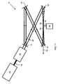
- FIG. 1 is a schematic illustration of an apparatus for generating high-intensity optical pulses comprising a laser, a beam transformer and an enhancement cavity including mirrors, two of which include central apertures.
- FIG. 2 is an illustrative depiction of the configuration of two apertured mirrors oppositely spaced apart for focused reflection of a light pulse about a central aperture in the mirrors.
- FIG. 3 is a plot of an example of intensity gain, g, of a pulse as a function of the pulse's wavelength.
- FIG. 4 is a plot of an example of spot size, as a function of pulse wavelength.
- FIG. 5 is a plot of an example of intensity gain, g, of a pulse as a function of the radius curvature, R, of the apertured mirrors.
- FIG. 6 is a plot of an example of spot size, as a function of the radius curvature, R, of the apertured mirrors.
- FIG. 7 is a plot of an example of intensity gain, g, as a function the average radius, r, of the apertured mirrors from a central axis.
- FIG. 8 is a plot of an example of spot size as a function the average radius, r, of the apertured mirrors from a central axis.
- FIG. 9 is a schematic illustration of using the enhancement cavity to accelerate a charged particle.
- FIG. 10 is a schematic illustration of using the enhancement cavity to generate x-rays via interaction of the enhanced pulse with an electron beam.
- FIG. 11 is a schematic illustration of using the enhancement cavity to generate ultraviolet light via interaction of the enhanced pulse with a rare gas.
- spatially relative terms such as “above,” “upper,” “beneath,” “below,” “lower,” and the like, may be used herein for ease of description to describe the relationship of one element to another element, as illustrated in the figures. It will be understood that the spatially relative terms are intended to encompass different orientations of the apparatus in use or operation in addition to the orientation depicted in the figures. For example, if the apparatus in the figures is turned over, elements described as “below” or “beneath” other elements or features would then be oriented “above” the other elements or features. Thus, the exemplary term, “above,” may encompass both an orientation of above and below. The apparatus may be otherwise oriented (e.g., rotated 90 degrees or at other orientations) and the spatially relative descriptors used herein interpreted accordingly.
- an embodiment of the apparatus includes an enhancement cavity 10 including four dispersion-free or low-dispersion mirrors 12 / 12 ′/ 12 ′′, wherein at least two of the mirrors 12 ′ are curved and include central apertures with a diameter of at least 1 mm (e.g., between 1 mm and 5 mm).
- the remaining mirrors 12 and 12 ′′ can have a flat, continuous reflecting surface, omitting the central apertures.
- more or fewer than four mirrors 12 , 12 ′, and 12 ′′ can be used depending, for example on the desired configuration and/or path length for the optical pulses in the enhancement cavity 10 .
- the enhancement cavity 10 is maintained under vacuum (i.e., at a pressure well below ambient), e.g., by placing the mirrors in a vacuum enclosure and attaching a vacuum pump to evacuate the enclosure.
- the enhancement cavity 10 is passive, meaning that the components of the enhancement cavity 10 do not contribute energy to the optical pulses in the cavity 10 ; in contrast, an “active”enhancement cavity may include a laser medium inside it, providing additional gain to the optical pulses, which may compensate for losses therein.
- a laser 14 such as a mode-locked laser (e.g., a diode-pumped Yb-based solid-state or fiber laser) or a fiber laser, or an amplifier or a combination thereof generates the optical pulses 16 , which can have a Gaussian distribution.
- the pulse length can be as low as, e.g., 5 to 10 femtoseconds.
- the intensity distribution of the optical pulses is shifted to a ring shape (with a reduced intensity at the center and with a spatial pattern similar to that of a truncated Bessel beam) by a mode converter 18 , such as a beam transformer (including, for example, an axicon) or, in the case of fiber lasers, a long-period grating.
- the ring-shaped pulses are coherently added in the enhancement cavity 10 to produce a higher-intensity enhanced optical pulse 22 via constructive interference.
- the laser 14 and enhancement cavity 10 are locked to each other so that light pulses travelling in the enhancement cavity are increased by addition of light pulses into the cavity 10 .
- the enhancement cavity 10 has high quality factor, Q, which is promoted by the cavity being passive; a high finesse, F; and a roundtrip time (i.e., the time required to traverse a full loop across the optical pathway defined by the mirrors 12 / 12 ′/ 12 ′′) of T R .
- Aggregated pulses fill the cavity 10 to near maximum capacity after a loading time of T load , which approximately equals the product of T R and F.
- a particular challenge associated with HHG is that an optical intensity of 10 13 W/cm 2 (and preferably up to about 10 15 W/cm 2 or slightly above) is typically needed to excite the rare gas, while the surface of the dielectric mirrors typically can withstand a peak intensity of only about 10 10 -10 12 W/cm 2 , depending on the fabrication process.
- the intensity in the middle of the cavity can be made two or three orders of magnitude higher than the intensity at the surface of the mirrors using the mirrors, configurations and methods described herein.
- Using a tight focusing cavity is a less desirable option because the mirrors will be located toward the edge of stability and also because the rapidly changing phase at the focus limits the length over which HHG can occur without being limited severely by phase mismatch.
- the use of mirrors with large apertures also enables an output coupling efficiency of the harmonic radiation of nearly 100%.
- the mirrors 12 ′ having the central apertures 26 have a radius of curvature, R (e.g., in the range from 10 to 40 cm, for example, 20 cm); an average radius, r, from a central axis 24 (e.g., in the range from 1 to 2 mm, for example, 1.5 mm); and a ring thickness, ⁇ r (e.g., in the range from 500 to 1200 ⁇ m), where ⁇ is the wavelength of the driving laser (e.g., in the range from 500 nm to 2.5 ⁇ m, for example, 1 ⁇ m).
- ⁇ r can be estimated:
- the average radius, r in specific embodiments is less than R/100.
- the cavity gain, g can be estimated as
- the enhanced optical pulse can interact with, e.g., a charged particle, electron or rare gas (e.g., helium, neon, argon, krypton, and/or xenon), can be estimated as
- this enhancement cavity allows for an intensity gain of three orders of magnitude, reaching energy intensities compatible with high harmonic generation at the focus (e.g., on the order of 10 13 , 10 14 or 10 15 W/cm 2 ), while not damaging the mirrors.
- the total optical path length defined by the mirrors 12 / 12 ′/ 12 ′′ and traversed as a loop by the enhanced pulse in the enhancement cavity 10 can be in the range from 10 cm to 3 meters.
- FIG. 3 An example of the relationship of intensity gain, g, as a function of wavelength, ⁇ , is illustrated in FIG. 3 , while an example of the relationship of spot size (measured as full width at half maximum at the focus) as a function of ⁇ is plotted in FIG. 4 for the same embodiment.
- FIG. 5 An example of the relationship of intensity gain, g, as a function of radius of curvature, R, is shown in FIG. 5 , while an example of the relationship of spot size (measured as full width at half maximum at the focus) as a function of R is plotted in FIG. 6 for the same embodiment.
- FIG. 7 An example of the relationship of intensity gain, g, as a function of average radius, r, is shown in FIG. 7 , while an example of the relationship of spot size (measured as full width at half maximum at the focus) as a function of r is plotted in FIG. 8 for the same embodiment.
- the mirrors 12 , 12 ′, 12 ′′ are model No. PR1-633-99-0537-0.15CC concave mirrors from CVI Lasers of Albuquerque, N. Mex. These mirrors are dielectric mirrors with a power reflectance between 98.5% and 99.5%.
- the average radius of the ring (i.e., the remaining portion of the mirror after the aperture is formed) in the apertured mirrors 12 ′ from a central axis 24 of substantial radial symmetry is 1.3 mm because of a 15 cm curvature and paring with an axicon with a 175° cone angle.
- a layer of positive photoresist (e.g., S1813 resist) can be deposited on each mirror through which an apertures is to be formed.
- a mask shaped like a ring (having the pattern shape of the resulting mirrors 12 ′) can be placed on the positive photoresist, and the masked mirror can then be exposed to 400 mm light for the lithography step.
- the exposed mirror can then be etched using an ammonium fluoride/potassium fluoride etching paste to form the central aperture 26 in the mirror.
- an apertured mirror 12 ′ produced via this method had a rough border for approximately 25 ⁇ m, while the preserved portion was highly circular and precise.
- the exposed mirror can be etched in hydrofluoric (HF) acid.
- One of the mirrors 12 serves as an output (input) coupler through which the optical pulse 16 enters the enhancement cavity.
- the mirror 12 serving as the output coupler can have an output coupling coefficient of 0.1% to 10%, and the input pulse 16 is critically matched with the enhanced pulse 22 circulating in the cavity 10 .
- the width of a transverse cavity resonance will be approximately 1 nm.
- the optical separation of the mirrors 12 , 12 ′, 12 ′′ can, therefore, be targeted for a stability within 1 Angstrom of a resonance.
- a feedback system moved by a piezoelectric stack can be employed to control one of the cavity mirrors 12 , 12 ′, 12 ′′.
- the mirror control signal can be supplemented with a high-frequency sinusoidal signal (e.g., at 10 kHz) that produces small oscillations around the operating point.
- a photodetector collects the output of a second mirror, and the output signal from the photodetector is used to measure the small signal gain at the operating point by homodyne detection of the 10 kHz signal.
- the local small signal gain i.e., the gain of the HF signal
- the local small signal gain is proportional to the slope of the resonance peak, and in particular will be zero at the maximum, and vary linearly around it.
- a charged particle accelerator using the enhancement cavity is shown in FIG. 9 , wherein a charged particle 32 , such as a subatomic particle (e.g., an electron, positron or proton), from, e.g., an electron source 38 including a photocathode gun 62 and focusing magnet 64 , are directed into the enhancement cavity 10 , through the central aperture of an apertured mirror 12 ′ into the path of the enhanced optical pulse 22 .
- the charged particle 32 is traveling in the same direction as the enhanced optical pulse 22 is traveling between the apertured mirrors 12 ′.
- the enhanced optical pulse 22 intersects the charged particle 32 at a spot area 20 representing a focal point for the apertured mirrors 12 ′, and energy from the enhanced optical pulse 22 is thereby transferred to the charged particle 32 to accelerate the charged particle 32 .
- the optical pulse 22 can be made radially polarized by appropriate polarization optics prior to coupling into the cavity for maximum charged particle acceleration.
- the accelerated charged particle 32 then passes through the central aperture of the apertured mirror 12 ′ on the opposite side of the enhancement cavity 10 and exits the enhancement cavity 10 .
- this accelerator structure may also be used for conditioning charged particle beams, e.g., bunching, for further use.
- an electron beam 36 is directed from an electron source 38 (such as a photocathode gun 62 , focusing magnet 64 , and accelerator 66 ) into the enhancement cavity through an aperture in an apertured mirror 12 ′ into the pathway of the enhanced linearly polarized optical pulse 22 in a direction opposite to the direction the enhanced optical pulse 22 is traveling between the mirrors 12 ′.
- the enhanced optical pulse 22 intersects the electron beam 36 at a spot area 20 and consequently strips energy from the electron beam 36 to release x-rays 40 .
- the electron beam 36 can be focused and guided into the cavity and through the mirrors 12 ′ via magnets.
- the electron beam 36 Upon exiting the enhancement cavity 10 with the generated x-rays 40 , the electron beam 36 can be peeled away from its linear trajectory by a magnet, thereby separating the electron beam 36 from the generated x-rays 40 . Further discussion regarding the use of an enhancement cavity and an electron source to generate x-rays can be found in U.S. Pat. No. 7,391,850 B2 (F. Kaertner, et al., “Compact, High-Flux Short-Pulse X-Ray Source”).
- a rare gas stream is flowed through the path of the enhanced optical pulse 22 in the enhancement cavity 10 .
- a T-shaped conduit 44 extends into the enhancement cavity and is coupled with a compressed rare-gas source 46 (e.g., a compressed gas tank filled with a rare gas).
- the top section of the conduit 44 is about 1 cm long and includes a pair of open ends 50 on either side of the spot area 20 in the cavity.
- the rare gas escapes, and the focused linearly polarized optical pulse 22 pass through, such that the energy of the enhanced optical pulse rips electrons off the rare gas atoms; when the electrons recombine with the rare gas atoms, ultraviolet radiation 52 is emitted and directed through the apertured mirror 12 ′ on an opposite side of the enhancement cavity 10 .
- the apertured mirror 12 ′ In this embodiment, only the mirror 12 ′ through which the ultraviolet radiation passes needs to include the aperture.
- a vacuum pump removes the emitted rare gas from the enhancement cavity after the gas leaves the conduit 44 .
- parameters for various properties are specified herein for embodiments of the invention, those parameters can be adjusted up or down by 1/100 th , 1/50 th , 1/20 th , 1/10 th , 1 ⁇ 5 th , 1 ⁇ 3 rd , 1 ⁇ 2, 3 ⁇ 4 th , etc. (or up by a factor of 2, 5, 10, etc.), or by rounded-off approximations thereof, unless otherwise specified.
- this invention has been shown and described with references to particular embodiments thereof, those skilled in the art will understand that various substitutions and alterations in form and details may be made therein without departing from the scope of the invention.
- stages are recited in a particular order—with or without sequenced prefacing characters added for ease of reference—the stages are not to be interpreted as being temporally limited to the order in which they are recited unless otherwise specified or implied by the terms and phrasing.
Abstract
Description
from which it follows that Δr˜√{square root over (λR)}. The average radius, r, in specific embodiments is less than R/100. For the same example cavity arrangement, the cavity gain, g, can be estimated as
while spot size, w0, at a focus point in the center of the cavity (i.e., midway right-to-left, as illustrated, between the mirrors), where the enhanced optical pulse can interact with, e.g., a charged particle, electron or rare gas (e.g., helium, neon, argon, krypton, and/or xenon), can be estimated as
Therefore, this enhancement cavity allows for an intensity gain of three orders of magnitude, reaching energy intensities compatible with high harmonic generation at the focus (e.g., on the order of 1013, 1014 or 1015 W/cm2), while not damaging the mirrors.
Claims (7)
Priority Applications (1)
| Application Number | Priority Date | Filing Date | Title |
|---|---|---|---|
| US12/894,620 US8649086B2 (en) | 2009-09-30 | 2010-09-30 | Apparatus and method for generating high-intensity optical pulses with an enhancement cavity |
Applications Claiming Priority (2)
| Application Number | Priority Date | Filing Date | Title |
|---|---|---|---|
| US24713909P | 2009-09-30 | 2009-09-30 | |
| US12/894,620 US8649086B2 (en) | 2009-09-30 | 2010-09-30 | Apparatus and method for generating high-intensity optical pulses with an enhancement cavity |
Publications (2)
| Publication Number | Publication Date |
|---|---|
| US20110073784A1 US20110073784A1 (en) | 2011-03-31 |
| US8649086B2 true US8649086B2 (en) | 2014-02-11 |
Family
ID=43779258
Family Applications (1)
| Application Number | Title | Priority Date | Filing Date |
|---|---|---|---|
| US12/894,620 Expired - Fee Related US8649086B2 (en) | 2009-09-30 | 2010-09-30 | Apparatus and method for generating high-intensity optical pulses with an enhancement cavity |
Country Status (2)
| Country | Link |
|---|---|
| US (1) | US8649086B2 (en) |
| WO (1) | WO2011041493A2 (en) |
Families Citing this family (6)
| Publication number | Priority date | Publication date | Assignee | Title |
|---|---|---|---|---|
| WO2012031607A1 (en) | 2010-09-06 | 2012-03-15 | Max-Planck-Gesellschaft Zur Förderung Der... | Method of generating enhanced intra-resonator laser light, enhancement resonator and laser device |
| DE102011082821A1 (en) * | 2011-09-16 | 2012-10-04 | Carl Zeiss Smt Gmbh | Extreme-UV radiation source for use in e.g. reflectometer of projection exposure system for extreme UV-lithography to manufacture memory chip, has overlapping device arranged in optical path to overlap electronic radiation with light rays |
| EP2700986A1 (en) * | 2012-08-24 | 2014-02-26 | Deutsches Elektronen-Synchrotron DESY | Device and method for enhancing the intensity of a laser beam |
| US9769913B2 (en) | 2013-02-01 | 2017-09-19 | Inter-University Research Institute Corporation High Energy Accelerator Research Organization | Burst-laser generator using an optical resonator |
| JP6233857B2 (en) * | 2013-02-01 | 2017-11-22 | 大学共同利用機関法人 高エネルギー加速器研究機構 | Two-dimensional four-mirror resonator |
| US10527492B2 (en) * | 2017-05-16 | 2020-01-07 | Li-Cor, Inc. | Mode matching method for absorption spectroscopy systems |
Citations (6)
| Publication number | Priority date | Publication date | Assignee | Title |
|---|---|---|---|---|
| US3909744A (en) * | 1973-09-24 | 1975-09-30 | United Technologies Corp | Unstable resonator system producing a high irradiance beam in the far field |
| US5394411A (en) * | 1994-02-16 | 1995-02-28 | University Of Maryland, College Park | Method for producing high intensity optical through x-ray waveguide and applications |
| US5963359A (en) | 1995-01-31 | 1999-10-05 | Oki Electric Industry Co., Ltd. | Wavelength conversion device employing non-diffracting beam |
| US20060268949A1 (en) * | 2005-05-24 | 2006-11-30 | Christoph Gohle | Method and radiation source for generating pulsed coherent radiation |
| US7321604B2 (en) * | 2004-01-07 | 2008-01-22 | The Regents Of The University Of Michigan | Ultra-short wavelength x-ray system |
| US7391850B2 (en) | 2005-03-25 | 2008-06-24 | Massachusetts Institute Of Technology | Compact, high-flux, short-pulse x-ray source |
Family Cites Families (5)
| Publication number | Priority date | Publication date | Assignee | Title |
|---|---|---|---|---|
| US4039962A (en) * | 1974-08-01 | 1977-08-02 | John Leonard Hughes | System for amplifying laser beams |
| US3947127A (en) * | 1974-11-11 | 1976-03-30 | The United States Of America As Represented By The Secretary Of The Navy | Optical component functional tester |
| US5220463A (en) * | 1991-01-29 | 1993-06-15 | Clark Instrumentation, Inc. | Optical delay line |
| JP3540741B2 (en) * | 2000-11-30 | 2004-07-07 | 独立行政法人 科学技術振興機構 | Variable cavity length laser cavity and pulsed laser light source device |
| US7291850B2 (en) * | 2005-04-08 | 2007-11-06 | Asml Netherlands B.V. | Lithographic apparatus and device manufacturing method |
-
2010
- 2010-09-30 WO PCT/US2010/050841 patent/WO2011041493A2/en active Application Filing
- 2010-09-30 US US12/894,620 patent/US8649086B2/en not_active Expired - Fee Related
Patent Citations (7)
| Publication number | Priority date | Publication date | Assignee | Title |
|---|---|---|---|---|
| US3909744A (en) * | 1973-09-24 | 1975-09-30 | United Technologies Corp | Unstable resonator system producing a high irradiance beam in the far field |
| US5394411A (en) * | 1994-02-16 | 1995-02-28 | University Of Maryland, College Park | Method for producing high intensity optical through x-ray waveguide and applications |
| US5963359A (en) | 1995-01-31 | 1999-10-05 | Oki Electric Industry Co., Ltd. | Wavelength conversion device employing non-diffracting beam |
| US7321604B2 (en) * | 2004-01-07 | 2008-01-22 | The Regents Of The University Of Michigan | Ultra-short wavelength x-ray system |
| US7391850B2 (en) | 2005-03-25 | 2008-06-24 | Massachusetts Institute Of Technology | Compact, high-flux, short-pulse x-ray source |
| US20060268949A1 (en) * | 2005-05-24 | 2006-11-30 | Christoph Gohle | Method and radiation source for generating pulsed coherent radiation |
| US7672342B2 (en) | 2005-05-24 | 2010-03-02 | MAX-PLANCK-Gesellschaft zur Förderung der Wissenschaften e.V. | Method and radiation source for generating pulsed coherent radiation |
Non-Patent Citations (2)
| Title |
|---|
| Korean Intellectual Property Office, "International Search Report and Written Opinion" (for PCT/US2010/050841-PCT application corresponding to present US application) (Jun. 23, 2011). |
| Moll, Kevin D., et al., "Output Coupling Methods for Cavity-Based High-Harmonic Generation", 14 Optics Express 8189-8197 (Sep. 4, 2006). |
Also Published As
| Publication number | Publication date |
|---|---|
| US20110073784A1 (en) | 2011-03-31 |
| WO2011041493A3 (en) | 2011-08-18 |
| WO2011041493A2 (en) | 2011-04-07 |
Similar Documents
| Publication | Publication Date | Title |
|---|---|---|
| US8649086B2 (en) | Apparatus and method for generating high-intensity optical pulses with an enhancement cavity | |
| US8704198B2 (en) | Efficient high-harmonic-generation-based EUV source driven by short wavelength light | |
| US8976834B2 (en) | Method of generating enhanced intra-resonator laser light, enhancement resonator and laser device | |
| US20130250402A1 (en) | Laser beam amplifier and laser apparatus using the same | |
| US7321604B2 (en) | Ultra-short wavelength x-ray system | |
| Joshi et al. | Resonant self-focusing of laser light in a plasma | |
| Raeder et al. | Developments towards in-gas-jet laser spectroscopy studies of actinium isotopes at LISOL | |
| WO2015067467A1 (en) | Free electron laser | |
| US9685756B2 (en) | Laser amplifier, laser apparatus, and extreme ultraviolet light generating system | |
| Shaw et al. | High-peak-power surface high-harmonic generation at extreme ultra-violet wavelengths from a tape | |
| EP2946447B1 (en) | Enhancement resonator including non-spherical mirrors | |
| Li et al. | Generalized longitudinal strong focusing in a steady-state microbunching storage ring | |
| US8391324B2 (en) | Intense optical high field generator in optical oscillator utilizing chirped pulse amplification | |
| US8885684B2 (en) | Gas laser device | |
| US10468225B2 (en) | Electron source for a free electron laser | |
| Boutu et al. | Overview on HHG high-flux sources | |
| Endo | High-average power EUV light source for the next-generation lithography by laser-produced plasma | |
| Mysyrowicz | Applications of ultrashort optical pulses | |
| Mizoguchi et al. | Development of CO 2 laser produced Xe plasma EUV light source for microlithography | |
| JP5474891B2 (en) | Light source device and exposure apparatus using the same | |
| Zhang et al. | Coherent free-electron light sources | |
| Ozawa et al. | VUV Frequency Comb Generation And Its Applications | |
| Pham | Review of Efficient Generation of Ultra-intense Few-cycle Radially Polarized Laser Pulses | |
| Madey et al. | Van de Graaf-based 13.5 nm inverse-Compton light source | |
| Pennington et al. | Laser Research and Development Studies for Laser Guide Star Systems |
Legal Events
| Date | Code | Title | Description |
|---|---|---|---|
| AS | Assignment |
Owner name: MASSACHUSETTS INSTITUTE OF TECHNOLOGY, MASSACHUSET Free format text: ASSIGNMENT OF ASSIGNORS INTEREST;ASSIGNORS:KAERTNER, FRANZ X.;ABRAM, GILBERTO;PUTNAM, WILLIAM P.;AND OTHERS;SIGNING DATES FROM 20101022 TO 20101209;REEL/FRAME:025499/0339 |
|
| AS | Assignment |
Owner name: UNITED STATES AIR FORCE, VIRGINIA Free format text: CONFIRMATORY LICENSE;ASSIGNOR:MASSACHUSETTS INSTITUTE OF TECHNOLOGY;REEL/FRAME:026420/0869 Effective date: 20110308 |
|
| FEPP | Fee payment procedure |
Free format text: PAYOR NUMBER ASSIGNED (ORIGINAL EVENT CODE: ASPN); ENTITY STATUS OF PATENT OWNER: MICROENTITY |
|
| STCF | Information on status: patent grant |
Free format text: PATENTED CASE |
|
| FEPP | Fee payment procedure |
Free format text: PATENT HOLDER CLAIMS MICRO ENTITY STATUS, ENTITY STATUS SET TO MICRO (ORIGINAL EVENT CODE: STOM); ENTITY STATUS OF PATENT OWNER: MICROENTITY |
|
| FPAY | Fee payment |
Year of fee payment: 4 |
|
| FEPP | Fee payment procedure |
Free format text: MAINTENANCE FEE REMINDER MAILED (ORIGINAL EVENT CODE: REM.); ENTITY STATUS OF PATENT OWNER: MICROENTITY |
|
| LAPS | Lapse for failure to pay maintenance fees |
Free format text: PATENT EXPIRED FOR FAILURE TO PAY MAINTENANCE FEES (ORIGINAL EVENT CODE: EXP.); ENTITY STATUS OF PATENT OWNER: MICROENTITY |
|
| STCH | Information on status: patent discontinuation |
Free format text: PATENT EXPIRED DUE TO NONPAYMENT OF MAINTENANCE FEES UNDER 37 CFR 1.362 |
|
| FP | Lapsed due to failure to pay maintenance fee |
Effective date: 20220211 |