US8646318B2 - Leak sensor apparatus for sensing moisture - Google Patents
Leak sensor apparatus for sensing moisture Download PDFInfo
- Publication number
- US8646318B2 US8646318B2 US12/319,195 US31919509A US8646318B2 US 8646318 B2 US8646318 B2 US 8646318B2 US 31919509 A US31919509 A US 31919509A US 8646318 B2 US8646318 B2 US 8646318B2
- Authority
- US
- United States
- Prior art keywords
- conductive line
- resistance
- layer
- line
- conductive
- Prior art date
- Legal status (The legal status is an assumption and is not a legal conclusion. Google has not performed a legal analysis and makes no representation as to the accuracy of the status listed.)
- Active, expires
Links
Images


Classifications
-
- G—PHYSICS
- G01—MEASURING; TESTING
- G01M—TESTING STATIC OR DYNAMIC BALANCE OF MACHINES OR STRUCTURES; TESTING OF STRUCTURES OR APPARATUS, NOT OTHERWISE PROVIDED FOR
- G01M3/00—Investigating fluid-tightness of structures
- G01M3/40—Investigating fluid-tightness of structures by using electric means, e.g. by observing electric discharges
-
- G—PHYSICS
- G01—MEASURING; TESTING
- G01M—TESTING STATIC OR DYNAMIC BALANCE OF MACHINES OR STRUCTURES; TESTING OF STRUCTURES OR APPARATUS, NOT OTHERWISE PROVIDED FOR
- G01M3/00—Investigating fluid-tightness of structures
- G01M3/02—Investigating fluid-tightness of structures by using fluid or vacuum
- G01M3/04—Investigating fluid-tightness of structures by using fluid or vacuum by detecting the presence of fluid at the leakage point
- G01M3/16—Investigating fluid-tightness of structures by using fluid or vacuum by detecting the presence of fluid at the leakage point using electric detection means
- G01M3/165—Investigating fluid-tightness of structures by using fluid or vacuum by detecting the presence of fluid at the leakage point using electric detection means by means of cables or similar elongated devices, e.g. tapes
-
- G—PHYSICS
- G01—MEASURING; TESTING
- G01M—TESTING STATIC OR DYNAMIC BALANCE OF MACHINES OR STRUCTURES; TESTING OF STRUCTURES OR APPARATUS, NOT OTHERWISE PROVIDED FOR
- G01M3/00—Investigating fluid-tightness of structures
- G01M3/02—Investigating fluid-tightness of structures by using fluid or vacuum
- G01M3/04—Investigating fluid-tightness of structures by using fluid or vacuum by detecting the presence of fluid at the leakage point
- G01M3/042—Investigating fluid-tightness of structures by using fluid or vacuum by detecting the presence of fluid at the leakage point by using materials which expand, contract, disintegrate, or decompose in contact with a fluid
- G01M3/045—Investigating fluid-tightness of structures by using fluid or vacuum by detecting the presence of fluid at the leakage point by using materials which expand, contract, disintegrate, or decompose in contact with a fluid with electrical detection means
-
- G—PHYSICS
- G01—MEASURING; TESTING
- G01N—INVESTIGATING OR ANALYSING MATERIALS BY DETERMINING THEIR CHEMICAL OR PHYSICAL PROPERTIES
- G01N27/00—Investigating or analysing materials by the use of electric, electrochemical, or magnetic means
- G01N27/02—Investigating or analysing materials by the use of electric, electrochemical, or magnetic means by investigating impedance
-
- Y—GENERAL TAGGING OF NEW TECHNOLOGICAL DEVELOPMENTS; GENERAL TAGGING OF CROSS-SECTIONAL TECHNOLOGIES SPANNING OVER SEVERAL SECTIONS OF THE IPC; TECHNICAL SUBJECTS COVERED BY FORMER USPC CROSS-REFERENCE ART COLLECTIONS [XRACs] AND DIGESTS
- Y10—TECHNICAL SUBJECTS COVERED BY FORMER USPC
- Y10T—TECHNICAL SUBJECTS COVERED BY FORMER US CLASSIFICATION
- Y10T137/00—Fluid handling
- Y10T137/0318—Processes
- Y10T137/0402—Cleaning, repairing, or assembling
- Y10T137/0441—Repairing, securing, replacing, or servicing pipe joint, valve, or tank
- Y10T137/0452—Detecting or repairing leak
Definitions
- the present invention relates to a leak sensor apparatus for sensing moisture, and a leak sensor apparatus for sensing moisture which can be easily installed at a possible leakage portion, by a tape method, such as a wall, a pipe, a facility or something without additionally using a bracket, and a sensor tape can be cut by a desired length and can be used.
- a tape method such as a wall, a pipe, a facility or something without additionally using a bracket
- a sensor tape can be cut by a desired length and can be used.
- leak sensors are widely used for sensing the leakage of water or oil.
- a cable type leak sensor a band type leak sensor, a module type lean sensor or something.
- the cable type leak sensor is basically directed to sensing water leakage or oil leakage and to fast informing even a leakage position.
- the sensing line senses a certain variation (electric potential difference) generating due to a resistance of leaked liquid in relation with the current flowing along a conductive line, which leads to an accurate sensing of water leakage or oil leakage, and even leads to a recognition of leakage position.
- the cable type leak sensor costs too much for installing the same, and since the length of a sensor cable is limited to 7 m, 15 m, and 30 m, a customer cannot select a desired length of the product. Since it is disadvantageous that a bracket is additionally needed for installing a sensor, an installation work is hard, and the installation of the bracket requires additional cost. A lot of time is unnecessarily needed for overcoming leakage after the leakage is sensed, and a connection to external device needs a hard work.
- the resistance value settable by a leak sensor is 0 ⁇ ⁇ 50 ⁇ , and the output ranges from 30V DC in maximum to 100 mA, and the length of an electric line is 50 m in maximum, and the length of a band sensor is 10 m in maximum.
- the band type leak sensor is able to sense the leakage of water or oil with respect to a relatively wider area at a lower cost, and the installation is easier, but a lot of errors occur with respect to a high humidity or an external impact, and it is not easy to sense a correct leak position.
- Related works for installation are not uniform, a lot of hard work is needed for installing the same.
- it is disadvantageous that a lot of investments are needed for the construction of a network or a PC use. Since the length of a cable for sensing a leakage of water or oil is limited to 1 m, 2 m, 5 m, 10 m and 20 m, a selectable range by customers is very limited.
- the price is relatively high for its performance, and a bracket for fixing the sensor on a bottom where the sensor is to be installed is additionally needed, which leads to a hard installation work and an additional cost.
- no connection device is provided except the relay contact point method.
- a photo sensor (light receiving part and light emitting part) is disposed in a plastic casing. In a state that liquid is not detected, a beam from the light emitting part is received, but when the beam from the light emitting part senses the liquid, a refraction index changes, so that the beam cannot be inputted into the light receiving part.
- the module type leak sensor senses the leakage of water or oil.
- the input voltage of the above device is 12V DC, and the response time is 50 msm and the available temperature is ⁇ 10° C. ⁇ 60° C.
- the sensor casing is preferably made of polypropylene.
- the module type leak sensor is able to sense a possible leakage portion at a lower cost, and the installation does not cost too much, and an audio alarm and a light alarm can be generated irrespective of surrounding peripherals. No errors due to moisture occur.
- the module type leak sensor is disadvantageously able to sense a very limited specific portion as compared to the cable type leak sensor, and a connection to peripherals needs a very hard work. Since an additional sensor fixing method is needed, a lot of time is needed when installing the product. Since it is designed to sense a very limited specific portion, when the position of leakage changes, it is impossible to detect the changed leaking portion.
- a tape method such as a wall, a pipe, a facility or something without additionally using a bracket
- a sensor tape can be cut by a desired length and can be used.
- an improved leak sensor apparatus for sensing moisture which is prepared in such a manner that a base film layer, a conductive line layer and a protection film layer are sequentially stacked on its lower surface in an upward direction, and the conductive line layer includes a resistance line having a certain resistance value per unit area in a longitudinal direction, and a conductive line which is spaced apart from the resistance line and is formed in parallel with respect to the resistance line, and the protection film layer is provided with a plurality of holes which are formed at regular intervals so that the resistance line and the conductive line of the conductive line layer can be exposed to the outside through the holes, respectively.
- the resistance lines and the conductive lines of the conductive line layer are formed in a mirror shape in multiple numbers, respectively.
- Two conductive lines are further formed in longitudinal directions in the conductive line layer, and resistance members are formed between the conductive lines at regular intervals, respectively.
- FIG. 1 is a cross sectional view illustrating a moisture sensing tape according to the present invention
- FIG. 2 is a view illustrating a pattern of a conductive line layer
- FIG. 3 is a circuit diagram of a pattern for a leak sense
- FIG. 4 is a circuit diagram of a pattern for a tape cutting sense
- FIG. 5 is a view illustrating a type of a protection film layer
- FIG. 6 is a view of another example of a leak sensor apparatus for sensing moisture according to the present invention.
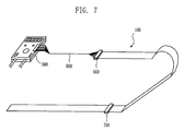
- FIG. 7 is a view illustrating a connection state between a controller and another tape.
- FIG. 1 is a cross sectional view illustrating a moisture sensing tape 100 according to the present invention.
- the moisture sensing tape 100 comprises an adhesive layer 200 , a base film layer 300 , a conductive line layer 400 , and a protection film layer 500 , which are all sequentially stacked on its lower surface in an upward direction.
- the adhesive layer 200 is attached to a possible leakage portion and is formed of an adhesive tape.
- the base film layer 300 is a layer for forming the conductive line layer 400 on its upper side and is made of a material of PET, PE, PTFE, PVC or other Tefrons for implementing an insulation function and for forming a certain pattern of the conductive line layer 400 .
- the conductive line layer 400 is a layer in which a plurality of conductive lines and resistance members are formed in a certain pattern shape and is disposed on an upper surface of the base film layer 300 in a strip shape while being spaced apart in parallel in a longitudinal direction of the moisture sensing tape 100 .
- the protection film layer 39 is stacked on an upper side of the conductive line layer 400 for protecting a pattern of the conductive line layer 400 from an external impact, stimulation or something and is preferably made of a certain material such as PET, PE, PVC or Tefrons.
- FIG. 2 is a view illustrating a pattern formation state of the conductive line layer 400 .
- the resistance lines 401 , 402 , 406 and 407 are formed of conductive lines 403 , 404 , 408 , 409 , 410 and 411 printed with silver compound, and a resistance member 412 .
- the first resistance line 401 is formed on an outer most portion in the longitudinal direction of the conductive line layer 400 and has a constant resistance value per unit area, and a second resistance line 402 is spaced apart inside the first resistance line 401 in the same shape as the first resistance line 401 .
- Double-structure conductive lines 403 and 404 printed with a silver compound, respectively, are spaced apart inside the second resistance line 402 and are sequentially formed.
- the resistance lines 401 and 402 and the conductive lines 403 and 404 form a leak sensing circuit
- the first conductive line 403 , the first resistance line 401 , the second conductive line 404 and the second resistance line 402 are connected with one another in series by means of a connection apparatus, respectively.
- the resistance lines 406 and 407 and the conductive lines 408 and 409 are formed on the upper surface of the conductive line layer 400 in the mirror shape along with the resistance lines 401 and 402 and the conductive lines 403 and 404 while being identically formed on both the outer side and inner side.
- the conductive lines 403 , 404 , 408 and 409 are made of pure conductive materials such as silver, etc. and each have a resistance of 0 ⁇ 20 ⁇ , and the resistance lines 401 , 402 , 406 and 407 each have a resistance of about 50 ⁇ 500 ⁇ .
- two conductive lines 410 and 411 are spaced apart from each other between the resistance lines 406 and 407 and the conductive lines 408 and 409 which are formed in the mirror shape along with the resistance lines 401 and 402 and the conductive lines 403 and 404 .
- the portions between the conductive lines 410 and 411 are connected by means of the resistance member 412 , respectively, for thereby forming the circuit of FIG. 4 .
- the cut position can be reliably sensed.
- FIG. 5 is a view illustrating the construction of the protection film layer 500 .
- the protection film layer 500 is stacked on the upper side of the conductive line layer 400 , it can be substantially separated from the outside, so that the leakage cannot be sensed by means of the conductive line layer 400 when leakage occurs therein. So, a plurality of holes 510 are formed at regular intervals.
- the holes 510 are formed in various shapes such as a longitudinal groove, a circular groove or other shapes in the width wise direction of the moisture sensing tape 100 so that two resistance lines can be exposed through the holes 510 .
- the interval between the neighboring holes 510 is preferably 0.5 ⁇ 1.5 cm.
- the moisture sensing tape 100 is attached on a certain portion in which moisture will be sensed. Since the moisture sensing tape 100 is formed of an adhesive layer 200 on its lower side, it can be easily attached.
- the controller 900 receives a resistance value and a voltage value, and the distance depending on the resistance value and the voltage value is computed.
- the controller 10 compares the computed value with a set value and indicates a sensed distance, and generates alarm.
- the cut state is sensed. Since a plurality of the resistance members 412 are installed at regular intervals, respectively, as shown in FIG. 4 , when a certain section is cut, the resistance value of the resistance member just before the cut portion is read by the controller 900 for thereby computing the cut position.
- FIG. 7 is a view illustrating a state that a plurality of moisture sensing tapes 100 are extended and connected, and a connection state with the controller 900 .
- the moisture sensing tapes 100 are connected with one another by using a connector 700 .
- the conductive line layer 400 and the signal line 800 are connected through the connector 600 and are connected with the controller 900 .
- FIG. 6 is a view illustrating another pattern formation state of the conductive line layer 400 .
- the conductive lines 421 , 422 , 425 , 426 , 433 and 427 , 428 , 531 , 432 , 434 are spaced apart from one another and are sequentially formed in the mirror shape from both outer sides of the conductive line layer 400 .
- Resistance members 423 , 424 and 429 , 430 are formed in the conductive lines 421 , 422 and 427 , 428 , respectively, at regular intervals.
- the conductive lines 421 , 422 and 425 , 526 connected with the resistance members 423 and 424 form the circuit of FIG. 3 for thereby implementing a leakage sensing operation, and in the same manner, the conductive liens 427 , 428 and 431 , 432 connected with the resistance members 429 and 430 form the same circuit as the above.
- the circuit for sensing a cut state of the moisture sensing tape 100 is formed in the same manner as FIG. 2 .
- the resistance members 435 are connected between the conductive lines 433 and 434 corresponding to the intermediate portion at regular intervals, so that the cutting state can be sensed as shown in FIG. 4 .
- a leak sensor apparatus for sensing moisture since it can be easily attached to a possible leakage portion such as a wall, a pipe, a facility or something by an adhesive tape method, an installation is very easy.
- the leak sensor apparatus of the present invention can be easily installed without using a bracket. A user can cut the sensor tape by a desired length, which leads to a very economical effect.
- the tape film is made of PET, PTFE, PVC or something, it is very strong to a chemical solution such as strong acid, strong alkali, organic liquid, etc.
- a chemical solution such as strong acid, strong alkali, organic liquid, etc.
- a plurality of tapes can be connected with one controller (AMP), respectively, by cutting one sensor tape into multiple pieces.
- AMP controller
- the time needed for overcoming moisture leakage portions after the leakage is sensed is very short. Since the present invention is made of a tape film, overcoming the moisture leakages is very easy.
Landscapes
- General Physics & Mathematics (AREA)
- Physics & Mathematics (AREA)
- Chemical & Material Sciences (AREA)
- Immunology (AREA)
- Health & Medical Sciences (AREA)
- Life Sciences & Earth Sciences (AREA)
- General Health & Medical Sciences (AREA)
- Chemical Kinetics & Catalysis (AREA)
- Electrochemistry (AREA)
- Analytical Chemistry (AREA)
- Pathology (AREA)
- Biochemistry (AREA)
- Examining Or Testing Airtightness (AREA)
- Investigating Or Analyzing Materials By The Use Of Electric Means (AREA)
Abstract
Description
Claims (5)
Priority Applications (1)
| Application Number | Priority Date | Filing Date | Title |
|---|---|---|---|
| US12/319,195 US8646318B2 (en) | 2008-01-09 | 2009-01-02 | Leak sensor apparatus for sensing moisture |
Applications Claiming Priority (6)
| Application Number | Priority Date | Filing Date | Title |
|---|---|---|---|
| KR10-2008-0002591 | 2008-01-09 | ||
| KR20080002591 | 2008-01-09 | ||
| KR10-2008-0014847 | 2008-02-19 | ||
| KR1020080014847A KR100827385B1 (en) | 2008-01-09 | 2008-02-19 | Physical property leak sensor |
| US12372108P | 2008-04-10 | 2008-04-10 | |
| US12/319,195 US8646318B2 (en) | 2008-01-09 | 2009-01-02 | Leak sensor apparatus for sensing moisture |
Publications (2)
| Publication Number | Publication Date |
|---|---|
| US20090173143A1 US20090173143A1 (en) | 2009-07-09 |
| US8646318B2 true US8646318B2 (en) | 2014-02-11 |
Family
ID=39649651
Family Applications (1)
| Application Number | Title | Priority Date | Filing Date |
|---|---|---|---|
| US12/319,195 Active 2031-03-21 US8646318B2 (en) | 2008-01-09 | 2009-01-02 | Leak sensor apparatus for sensing moisture |
Country Status (2)
| Country | Link |
|---|---|
| US (1) | US8646318B2 (en) |
| KR (1) | KR100827385B1 (en) |
Cited By (3)
| Publication number | Priority date | Publication date | Assignee | Title |
|---|---|---|---|---|
| CN104913881A (en) * | 2015-04-28 | 2015-09-16 | 上海柳智科技股份有限公司 | Leakage liquid detection sensor of circuit formed by utilizing ion sputtering coating and manufacturing process of leakage liquid detection sensor |
| CN106017815A (en) * | 2015-03-26 | 2016-10-12 | Flownix株式会社 | Leak sensor for side detection |
| US10384002B2 (en) * | 2015-01-30 | 2019-08-20 | Mackay Memorial Hospital | Sensor patch, system, and method for detecting fluid leakage |
Families Citing this family (24)
| Publication number | Priority date | Publication date | Assignee | Title |
|---|---|---|---|---|
| KR100909242B1 (en) | 2008-04-24 | 2009-07-27 | (주)유민에쓰티 | Physical property leak sensor |
| KR100909241B1 (en) | 2008-07-21 | 2009-07-27 | (주)유민에쓰티 | Control device of property sensing leak sensing tape and remote monitoring device using the same |
| KR101195961B1 (en) | 2009-09-08 | 2012-10-30 | (주)유민에쓰티 | Water level sensing apparatus |
| GB2483681A (en) * | 2010-09-16 | 2012-03-21 | Burstalert Ltd | A Fluid Detection Tape and System Incorporating a Fluid Detection Tape |
| KR20130015854A (en) * | 2011-08-05 | 2013-02-14 | 유홍근 | Apparatus for detecting leakage of hydrocarbon liquid |
| JP6146596B2 (en) | 2013-02-04 | 2017-06-14 | ユミン システム テクノロジー カンパニー,リミテッド | Acid solution leak detector |
| CN106153514B (en) * | 2015-04-01 | 2018-12-11 | 广东聚胶粘合剂有限公司 | A kind of hot-fusible pressure-sensitive adhesive anti-reflective infiltration test method |
| KR101664393B1 (en) | 2015-04-10 | 2016-10-10 | 오토센서코리아(주) | Lekage water sensing system |
| KR101907190B1 (en) | 2015-07-28 | 2018-10-11 | 심충식 | Leak liquid sensing device and manufacturing method the same |
| KR101712392B1 (en) * | 2016-12-14 | 2017-03-07 | (주)하이큐브시스템 | Film layered type liquid detecting sensor |
| KR101884905B1 (en) | 2017-05-26 | 2018-08-02 | (주)유민에쓰티 | Leak liquid sensing device and manufacturing method the same |
| KR102116689B1 (en) * | 2017-06-29 | 2020-05-29 | 성백명 | Tape type reusable leak detection sensor |
| KR101969575B1 (en) | 2018-01-19 | 2019-08-20 | (주)유민에쓰티 | Leak liquid sensing device |
| KR102009968B1 (en) * | 2018-08-06 | 2019-08-12 | 아머스 주식회사 | Flexible flat component detection sensor |
| WO2020079532A1 (en) * | 2018-10-16 | 2020-04-23 | 3M Innovative Properties Company | Leak detector film |
| KR102316047B1 (en) * | 2019-05-21 | 2021-10-26 | (주)글로벌센서테크 | A leak detection sensor and a composite detection leak detection apparatus including the same |
| KR102128431B1 (en) | 2019-11-04 | 2020-06-30 | (주)유민에쓰티 | Leak liquid sensing device |
| DE102019134398B4 (en) * | 2019-12-13 | 2021-07-08 | bygg AI GmbH | Apparatus and method for detecting and localizing moisture |
| RU197833U1 (en) * | 2020-02-24 | 2020-06-02 | Владимир Семенович Мельников | Leak sensor |
| KR102344636B1 (en) | 2020-11-02 | 2021-12-29 | (주)유민에쓰티 | Capacitive leak detecting apparatus |
| DE102021002979A1 (en) | 2021-06-11 | 2022-12-15 | bygg Al GmbH | Method and device for detecting and locating moisture on moisture-carrying surfaces and/or in moisture-carrying layers |
| KR102451647B1 (en) | 2022-07-11 | 2022-10-07 | 주식회사 능인솔루션 | Liquid leak detector of daisy chain communication method |
| KR102502000B1 (en) | 2022-07-21 | 2023-02-23 | 주식회사 능인솔루션 | Method of liquid leak detecting film having Liquid leak detector of daisy chain communication method and liquid leak detecting film thereof |
| KR102919468B1 (en) | 2023-12-26 | 2026-01-30 | 오토센서코리아(주) | Leak sensor that detects organic composite and hydrocarbon fuel organic fluid |
Citations (4)
| Publication number | Priority date | Publication date | Assignee | Title |
|---|---|---|---|---|
| US4570477A (en) * | 1983-03-10 | 1986-02-18 | Junkosha Company Ltd. | Leak detecting cable |
| US4801865A (en) * | 1988-01-19 | 1989-01-31 | California Sensor Corporation | Moisture sensor probe with at least two groups of resistive arrays |
| US20080204259A1 (en) * | 2007-02-27 | 2008-08-28 | Vokey David E | Moisture detection sensor tape and probes to determine surface moisture and material moisture levels |
| US7948388B2 (en) * | 2005-07-20 | 2011-05-24 | Mcginty Joseph Ralph | Water detection unit and system |
Family Cites Families (1)
| Publication number | Priority date | Publication date | Assignee | Title |
|---|---|---|---|---|
| US7292155B2 (en) * | 2005-09-01 | 2007-11-06 | Detec Systems Llc | Moisture detection sensor tape with leak locate |
-
2008
- 2008-02-19 KR KR1020080014847A patent/KR100827385B1/en active Active
-
2009
- 2009-01-02 US US12/319,195 patent/US8646318B2/en active Active
Patent Citations (4)
| Publication number | Priority date | Publication date | Assignee | Title |
|---|---|---|---|---|
| US4570477A (en) * | 1983-03-10 | 1986-02-18 | Junkosha Company Ltd. | Leak detecting cable |
| US4801865A (en) * | 1988-01-19 | 1989-01-31 | California Sensor Corporation | Moisture sensor probe with at least two groups of resistive arrays |
| US7948388B2 (en) * | 2005-07-20 | 2011-05-24 | Mcginty Joseph Ralph | Water detection unit and system |
| US20080204259A1 (en) * | 2007-02-27 | 2008-08-28 | Vokey David E | Moisture detection sensor tape and probes to determine surface moisture and material moisture levels |
Cited By (4)
| Publication number | Priority date | Publication date | Assignee | Title |
|---|---|---|---|---|
| US10384002B2 (en) * | 2015-01-30 | 2019-08-20 | Mackay Memorial Hospital | Sensor patch, system, and method for detecting fluid leakage |
| CN106017815A (en) * | 2015-03-26 | 2016-10-12 | Flownix株式会社 | Leak sensor for side detection |
| CN106017815B (en) * | 2015-03-26 | 2020-01-03 | Flownix株式会社 | Leak sensor for lateral detection |
| CN104913881A (en) * | 2015-04-28 | 2015-09-16 | 上海柳智科技股份有限公司 | Leakage liquid detection sensor of circuit formed by utilizing ion sputtering coating and manufacturing process of leakage liquid detection sensor |
Also Published As
| Publication number | Publication date |
|---|---|
| US20090173143A1 (en) | 2009-07-09 |
| KR100827385B1 (en) | 2008-05-06 |
Similar Documents
| Publication | Publication Date | Title |
|---|---|---|
| US8646318B2 (en) | Leak sensor apparatus for sensing moisture | |
| EP2265917B1 (en) | Leak sensor apparatus for sensing moisture | |
| US9212965B2 (en) | Leak detection device and remote monitoring system having slave controllers with unique IDs | |
| US9354135B2 (en) | Oil leak detection device | |
| KR20110007501A (en) | Leak detection device | |
| KR101119823B1 (en) | Apparatus for sensing the leak a pipe connection part | |
| CN205785702U (en) | A kind of Novel strip belt sensor device detecting leakage | |
| KR101445310B1 (en) | Leak Sensing Apparatus | |
| KR102247905B1 (en) | Leak detection apparatus with heating function | |
| KR20110053883A (en) | Leak Detection Device with Heating Function | |
| KR101479177B1 (en) | Leak sensor for sensing moisture | |
| KR101200923B1 (en) | Capacitance type level sensor | |
| KR100909241B1 (en) | Control device of property sensing leak sensing tape and remote monitoring device using the same | |
| KR20100138523A (en) | Leak Detection Device with Fire Detection Function | |
| KR20200005851A (en) | Sensor for detecting liquid and device using the same | |
| KR20150131888A (en) | Water leak detection sensor | |
| KR102187189B1 (en) | Apparatus and method for detecting wire open and leakage | |
| KR101847090B1 (en) | Sensor for detecting Leak and location | |
| US11650124B2 (en) | Phase separation sensor | |
| KR101983660B1 (en) | Leak detection apparatus | |
| KR102053005B1 (en) | Liquid leak detect sensor of outdoors type | |
| KR102144641B1 (en) | Leak detection sensor | |
| JP2020079735A (en) | Measurement device for feature quantity and measurement method for the same | |
| KR102076294B1 (en) | Connectors with installed film-type harmful chemical solution leakage sensor |
Legal Events
| Date | Code | Title | Description |
|---|---|---|---|
| AS | Assignment |
Owner name: YUMIN SYSTEM TECHNOLOGY CO., LTD., KOREA, REPUBLIC Free format text: ASSIGNMENT OF ASSIGNORS INTEREST;ASSIGNOR:YU, HONG GEUN;REEL/FRAME:022088/0945 Effective date: 20081222 |
|
| STCF | Information on status: patent grant |
Free format text: PATENTED CASE |
|
| FEPP | Fee payment procedure |
Free format text: MAINTENANCE FEE REMINDER MAILED (ORIGINAL EVENT CODE: REM.) |
|
| FEPP | Fee payment procedure |
Free format text: SURCHARGE FOR LATE PAYMENT, SMALL ENTITY (ORIGINAL EVENT CODE: M2554) |
|
| MAFP | Maintenance fee payment |
Free format text: PAYMENT OF MAINTENANCE FEE, 4TH YR, SMALL ENTITY (ORIGINAL EVENT CODE: M2551) Year of fee payment: 4 |
|
| AS | Assignment |
Owner name: YUMIN SYSTEM TECHNOLOGY CO., LTD., KOREA, REPUBLIC Free format text: ASSIGNMENT OF ASSIGNORS INTEREST;ASSIGNOR:YU, DONG GEUN;REEL/FRAME:046515/0219 Effective date: 20180727 |
|
| MAFP | Maintenance fee payment |
Free format text: PAYMENT OF MAINTENANCE FEE, 8TH YR, SMALL ENTITY (ORIGINAL EVENT CODE: M2552); ENTITY STATUS OF PATENT OWNER: SMALL ENTITY Year of fee payment: 8 |
|
| MAFP | Maintenance fee payment |
Free format text: PAYMENT OF MAINTENANCE FEE, 12TH YR, SMALL ENTITY (ORIGINAL EVENT CODE: M2553); ENTITY STATUS OF PATENT OWNER: SMALL ENTITY Year of fee payment: 12 |