US8641130B2 - Vehicle cowl cover - Google Patents
Vehicle cowl cover Download PDFInfo
- Publication number
- US8641130B2 US8641130B2 US13/242,212 US201113242212A US8641130B2 US 8641130 B2 US8641130 B2 US 8641130B2 US 201113242212 A US201113242212 A US 201113242212A US 8641130 B2 US8641130 B2 US 8641130B2
- Authority
- US
- United States
- Prior art keywords
- yielding
- main body
- cowl cover
- cover assembly
- vehicle cowl
- Prior art date
- Legal status (The legal status is an assumption and is not a legal conclusion. Google has not performed a legal analysis and makes no representation as to the accuracy of the status listed.)
- Active, expires
Links
Images


Classifications
-
- B—PERFORMING OPERATIONS; TRANSPORTING
- B62—LAND VEHICLES FOR TRAVELLING OTHERWISE THAN ON RAILS
- B62D—MOTOR VEHICLES; TRAILERS
- B62D25/00—Superstructure or monocoque structure sub-units; Parts or details thereof not otherwise provided for
- B62D25/08—Front or rear portions
- B62D25/081—Cowls
-
- B—PERFORMING OPERATIONS; TRANSPORTING
- B60—VEHICLES IN GENERAL
- B60R—VEHICLES, VEHICLE FITTINGS, OR VEHICLE PARTS, NOT OTHERWISE PROVIDED FOR
- B60R13/00—Elements for body-finishing, identifying, or decorating; Arrangements or adaptations for advertising purposes
- B60R13/07—Water drainage or guide means not integral with roof structure
-
- B—PERFORMING OPERATIONS; TRANSPORTING
- B60—VEHICLES IN GENERAL
- B60R—VEHICLES, VEHICLE FITTINGS, OR VEHICLE PARTS, NOT OTHERWISE PROVIDED FOR
- B60R21/00—Arrangements or fittings on vehicles for protecting or preventing injuries to occupants or pedestrians in case of accidents or other traffic risks
- B60R21/34—Protecting non-occupants of a vehicle, e.g. pedestrians
- B60R2021/343—Protecting non-occupants of a vehicle, e.g. pedestrians using deformable body panel, bodywork or components
Definitions
- the present invention generally relates to a vehicle cowl cover. More specifically, the present invention relates to a vehicle cowl cover including at least one yielding portion having elasticity greater than that of the main body of the cowl cover to increase yielding characteristics of the vehicle cowl cover area.
- Vehicle designers are routinely seeking new ways to increase the safety of vehicles such as automobiles, trucks, SUVs, vans and so on. For example, vehicle designers consider many different scenarios that involve contact of the vehicle with objects (e.g., structures, other vehicles, pedestrians, foreign objects, etc.) while the vehicle is in motion. Naturally, vehicle designers continuously strive to design vehicles that can mitigate the intensity of forces applied to objects when such contact occurs.
- objects e.g., structures, other vehicles, pedestrians, foreign objects, etc.
- vehicle hood and cowl area One area of interest is the vehicle hood and cowl area, because a forward motion impact with an object typically results in contact between the object and this area of the vehicle.
- vehicle hoods are typically formed from stamped metal and tend to be fairly rigid components. Therefore, there may be practical limitations to the manner in which hood configurations can be changed to reduce the force that the hood may exert on an object during a collision.
- vehicles are designed to withstand a wide variety of weather and environmental conditions. Naturally, such vehicles are constructed to prevent or at least minimize the amount of water and debris that can accumulate on or within a vehicle. For example, rain water can collect and add weight to a vehicle, seep into various areas of the vehicle, or deposit unsightly residue when such water evaporates. Accordingly, rain water may need to be diverted so that the water does not collect within the body structure of the vehicle.
- a vehicle cowl cover including a main body and a first yielding portion.
- the main body includes a first lateral end portion defining a first end edge and a second lateral end portion defining a second end edge.
- the first yielding portion is attached along a majority of the first end edge such that the first yielding portion at least partially forms a first end surface of the first lateral end portion.
- the first yielding portion has a first elasticity greater than a second elasticity of the main body.
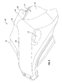
- FIG. 1 is a top view of a vehicle including a vehicle cowl cover according to a disclosed embodiment
- FIG. 2 is a perspective view of the vehicle cowl cover and associated components of the vehicle as shown in FIG. 1 ;
- FIG. 3 is a top plan view of the vehicle cowl cover
- FIG. 4 is a cross-sectional view of the vehicle cowl cover and surrounding area taken along lines 4 - 4 in FIG. 1 ;
- FIG. 5 is a front perspective view of a first side (e.g., a driver's side) of the vehicle cowl cover;
- FIG. 6 is a detailed side view of the driver side of the vehicle cowl cover
- FIG. 7 is a front perspective view of a second side (e.g., a front passenger's side) of the vehicle cowl cover;
- FIG. 8 is a detailed side view of the passenger side of the vehicle cowl cover
- FIG. 9 is a top perspective view of the driver side from a rear area of the vehicle cowl cover.
- FIG. 10 is a bottom perspective view of the driver side from the rear area of the vehicle cowl cover
- FIG. 11 is a detailed perspective view of the driver side of the vehicle cowl cover with the corresponding yielding portion removed;
- FIG. 12 is a detailed side view of the driver side of the vehicle cowl cover with the corresponding yielding portion removed;
- FIG. 13 is a front elevational view of the driver side of the vehicle cowl cover with the corresponding yielding portion removed;
- FIG. 14 is a top view of the driver side of the vehicle cowl cover with the corresponding yielding portion removed;
- FIG. 15 is a detailed plan view of openings defined through the driver side of the vehicle cowl cover
- FIG. 16 is a cross-sectional view of the yielding portion attached to the driver side of the vehicle cowl cover
- FIG. 17 is a side view of solely the yielding portion that attaches to the driver side of the vehicle cowl cover;
- FIG. 18 is a bottom perspective view of the yielding portion that attaches to the driver side of the vehicle cowl cover.
- FIG. 19 is a detailed perspective view of one of the retaining projections of the yielding portion shown in FIGS. 16 through 18 .
- an automotive vehicle 10 with a vehicle cowl cover 12 is illustrated according to an embodiment.
- the vehicle 10 is conventional, except for the vehicle cowl cover 12 as described herein. Accordingly, the vehicle 10 and its various parts will not be discussed and/or illustrated in detail herein, except as related to the vehicle cowl cover 12 .
- the vehicle 10 can be any type of vehicle such as an automobile, a truck, an SUV, a van and so on.
- the vehicle 10 includes a windshield 14 , a hood 16 , fender panels 18 and windshield wipers 20 , which can all be conventional as understood in the automotive art.
- the vehicle cowl cover 12 includes a main body 22 that at least partially covers a cowl box (not shown) of the vehicle 10 .
- the main body 22 of the vehicle cowl cover 12 can be made of metal, plastic, composite or any other suitable material.
- the vehicle cowl cover 12 can be configured as an integral-one piece unitary member, or as a plurality of components that are coupled together by snap fitting or by any suitable fastening members, such as adhesives, rivets, screws, bolts and so on as discussed below.
- the main body 22 includes windshield wiper apertures 24 that accommodate the rotating components (not shown) of the windshield wipers 20 .
- the main body 22 of the vehicle cowl cover 12 is mounted to vehicle body panels 26 , 28 and 30 of the vehicle 10 by any suitable fastening members 32 , such as rivets, screws, bolts and so on.
- the main body 22 includes an exterior surface 34 .
- the main body 22 includes a first body wall portion 36 and a second body wall portion 38 extending from the first body wall 36 portion to form a front exterior body surface 40 .
- the main body 22 includes a first lateral end portion 42 defining a first end edge 44 and a second lateral end portion 46 defining a second end edge 48 .
- the first end edge 44 defines a first cutaway section 50 that extends at least partially toward a central portion of the main body 22 .
- the second end edge 48 defines a second cutaway section 52 that extends at least partially toward the central portion of the main body 22 .
- the vehicle cowl cover 12 also includes a first yielding portion 54 and a second yielding portion 56 .
- the first yielding portion 54 is a one-piece unitary member
- the second yielding portion 56 is a one-piece unitary member.
- the first yielding portion 54 can comprise a plurality of components coupled together by, for example, snap fitting, adhesive, fasteners or in any other suitable manner to form the first yielding portion 54 .
- the second yielding portion 56 can comprise a plurality of components coupled together by, for example, snap fitting, adhesives, fasteners or in any other suitable manner to form the second yielding portion 56 .
- the first yielding portion 54 can be made of, for example, a rubber or other suitable elastic type of material having an elasticity (a first elasticity) greater than the elasticity (a second elasticity) of the main body 22 .
- the second yielding portion 56 can be made of, for example, a rubber or other suitable elastic type of material having an elasticity (a third elasticity) greater than the elasticity (a second elasticity) of the main body 22 .
- the first and second yielding portions 54 and 56 can be made of the same or similar materials, or different materials, as long as the elasticities of the first and second yielding portions 54 and 56 are each greater than the elasticity of the main body 22 .
- first yielding portion 54 is received within the first cutaway section 50 at the first end edge 44 of the main body 22 .
- second yielding portion 56 is received within the second cutaway section 52 at the second end edge 48 of the main body 22 .
- the first yielding portion 54 is attached along a majority of the first end edge 44 such that the first yielding portion 54 at least partially forms a first end surface 58 of the first lateral end portion 42 .
- the first yielding portion 54 further includes a first yielding exterior surface 60 configured such that a portion 62 of the first yielding exterior surface 60 aligns with or substantially aligns with the exterior surface 34 of the main body 22 . That is, the first yielding portion 54 includes a first yielding wall 64 and a second yielding wall 66 extending from the first yielding wall 64 to form a first front exterior yielding surface 68 .
- the first front exterior yielding surface 68 aligns with or substantially aligns with the front exterior body surface 40 .
- first yielding exterior surface 60 of the first yielding portion 54 can be viewed as including a first exterior surface 70 , a second exterior surface 72 and a third exterior surface 74 that are arranged to form a first exterior corner 76 of the vehicle cowl cover assembly 12 .
- the first yielding portion 54 includes a plurality of first projections 78 that are each retained in a respective one of a plurality of first openings 80 defined by the main body 22 .
- the main body 22 defines the first openings 80 proximate to the first end edge 44 .
- the first openings 80 are spaced apart from one another along the first end edge 44 of the first lateral end portion 42 .
- Each of the first projections 78 can be configured to snap-fit into a respective first opening 80 . For instance, as shown in FIG.
- a first projection 78 includes a first diameter portion 82 , a second diameter portion 84 that preferably has a width greater than or equal to the first diameter portion 82 and a tapered portion 86 that is formed between the first diameter portion 82 and the second diameter portion 84 .
- a step or surface 88 is formed at the end of the tapered portion 86 proximate to the second diameter portion 84 of the first projection 78 . Accordingly, when the first projection 78 is inserted into a respective first opening 80 , a force can be applied to the first diameter portion 82 to pull the tapered portion 86 through the first opening 80 .
- the step or surface 88 at the edge of the tapered portion 86 can thus retain the first projection 78 in the first opening 80 in a snap-fit type manner.
- the engagement of the first projections 78 with the openings 80 openings couples the first yielding portion 54 to the main body 22 .
- the main body 22 further defines a first body mounting opening 90 through the first lateral end portion 42 .
- the first body mounting opening 90 is configured to receive a fastener 92 , such as a rivet, bolt, screw, and so on, which couples the main body 22 to the vehicle 10 .
- the first yielding portion 54 defines a first yielding opening 94 that is axially aligned with the first body mounting opening 90 and configured to receive the fastener 92 therethrough.
- a section 96 of the first yielding portion 54 adjacent to the first yielding opening 94 covers a portion of the main body 22 adjacent to the first body mounting opening 90 .
- first yielding portion 54 defines a wall structure 98 configured to channel water away from the first lateral end portion 42 of the main body 22 .
- the main body 22 defines one of the windshield wiper apertures 24 through the first lateral end portion 42 , and the wall structure 98 faces the windshield wiper aperture 24 .
- the second yielding portion 56 is attached along a majority of the second end edge 48 in a manner similar to that in which the first yielding portion 54 is attached along a majority of the first end edge 44 .
- the second yielding portion 56 at least partially forms a second end surface 100 of the second lateral end portion 46 .
- the second yielding portion 56 includes second projections that are identical or similar to the first projections 78 as described above. Accordingly, the second projections are each retained in a respective one of a plurality of second openings that are defined through the main body 22 proximate to the second end edge 48 . Like the first openings 80 , the second openings are spaced apart from one another along the second end edge 48 of the second lateral end portion 46 . Thus, the engagement of the second projections with the second openings couples the second yielding portion 56 to the main body 22 .
- the second yielding portion 56 further includes a second yielding exterior surface 102 configured such that a portion 104 of the second yielding exterior surface 102 aligns with or substantially aligns with the exterior surface 34 of the main body 22 . That is, the second yielding portion 56 includes a first yielding wall 106 and a second yielding wall 108 extending from the first yielding wall 106 to form a second front exterior yielding surface 110 .
- the second front exterior yielding surface 110 aligns with or substantially aligns with the front exterior body surface 40 .
- the second yielding exterior surface 102 of the second yielding portion 56 can be viewed as including a first exterior surface 112 , a second exterior surface 114 and a third exterior surface 116 that are arranged to form a second exterior corner 118 of the vehicle cowl cover assembly 12 .
- the main body 22 further defines a second body mounting opening 120 through the second lateral end portion 46 .
- the second body mounting opening 120 is configured to receive a fastener 122 , such as a rivet, bolt, screw, and so on, which couples the main body 22 to the vehicle 10 .
- the second yielding portion 56 defines a second yielding opening 124 that is axially aligned with the second body mounting opening 120 and configured to receive the fastener 122 therethrough.
- a section 126 of the second yielding portion 56 adjacent to the second yielding opening 124 covers a portion of the main body 22 adjacent to the second body mounting opening 120 .
- the first and second yielding portions 54 and 56 are more easily deformable than the main body 22 of the vehicle cowl cover 12 . Therefore, the first and second yielding portions 54 and 56 can more readily absorb forces that would otherwise be applied to a colliding object (e.g., structure, other vehicle, pedestrian, foreign object, etc.) during forward vehicle movement.
- the vehicle cowl cover 12 can also assist with water management due to, for example, the configuration of the first yielding portion 54 .
- the term “comprising” and its derivatives, as used herein, are intended to be open ended terms that specify the presence of the stated features, elements, components, groups, integers, and/or steps, but do not exclude the presence of other unstated features, elements, components, groups, integers and/or steps.
- the foregoing also applies to words having similar meanings such as the terms, “including”, “having” and their derivatives.
- the terms “part,” “section,” “portion,” “member” or “element” when used in the singular can have the dual meaning of a single part or a plurality of parts.
- the following directional terms “outboard”, inboard”, “forward”, “rearward”, “above”, “downward”, “vertical”, “horizontal”, “below” and “transverse” as well as any other similar directional terms refer to those directions of a vehicle equipped with the present invention. Accordingly, these terms, as utilized to describe the present invention should be interpreted relative to a vehicle equipped with the present invention.
- the terms of degree such as “generally”, “substantially”, “about” and “approximately” as used herein mean a reasonable amount of deviation of the modified term such that the end result is not significantly changed. For example, two members that are angled less than ten degrees apart would be considered “generally perpendicular”, but two members that are angled more than fifteen degrees apart would not be considered “generally perpendicular”.
Landscapes
- Engineering & Computer Science (AREA)
- Mechanical Engineering (AREA)
- Chemical & Material Sciences (AREA)
- Combustion & Propulsion (AREA)
- Transportation (AREA)
- Body Structure For Vehicles (AREA)
Abstract
Description
Claims (20)
Priority Applications (1)
| Application Number | Priority Date | Filing Date | Title |
|---|---|---|---|
| US13/242,212 US8641130B2 (en) | 2011-09-23 | 2011-09-23 | Vehicle cowl cover |
Applications Claiming Priority (1)
| Application Number | Priority Date | Filing Date | Title |
|---|---|---|---|
| US13/242,212 US8641130B2 (en) | 2011-09-23 | 2011-09-23 | Vehicle cowl cover |
Publications (2)
| Publication Number | Publication Date |
|---|---|
| US20130076071A1 US20130076071A1 (en) | 2013-03-28 |
| US8641130B2 true US8641130B2 (en) | 2014-02-04 |
Family
ID=47910458
Family Applications (1)
| Application Number | Title | Priority Date | Filing Date |
|---|---|---|---|
| US13/242,212 Active 2032-01-10 US8641130B2 (en) | 2011-09-23 | 2011-09-23 | Vehicle cowl cover |
Country Status (1)
| Country | Link |
|---|---|
| US (1) | US8641130B2 (en) |
Cited By (7)
| Publication number | Priority date | Publication date | Assignee | Title |
|---|---|---|---|---|
| US20130214560A1 (en) * | 2010-09-28 | 2013-08-22 | Honda Motor Co., Ltd. | Structure for positioning cowl top for vehicle |
| US20140183898A1 (en) * | 2012-11-28 | 2014-07-03 | GM Global Technology Operations LLC | Motor vehicle trough module with seal |
| US20160280275A1 (en) * | 2013-11-11 | 2016-09-29 | Honda Motor Co., Ltd. | Cowl structure |
| US20170136849A1 (en) * | 2015-11-12 | 2017-05-18 | GM Global Technology Operations LLC | Water tank cover for a motor vehicle |
| US9862424B2 (en) * | 2015-09-02 | 2018-01-09 | Toyota Jidosha Kabushiki Kaisha | Vehicle front section structure |
| US20240174296A1 (en) * | 2022-11-30 | 2024-05-30 | Nissan North America, Inc. | Vehicle cowl assembly |
| US20250115303A1 (en) * | 2021-07-30 | 2025-04-10 | Valeo Systemes D'essuyage | Windshield wiper cowl assembly with a flush-mounted inset hose connector |
Families Citing this family (8)
| Publication number | Priority date | Publication date | Assignee | Title |
|---|---|---|---|---|
| US8840173B2 (en) * | 2011-07-11 | 2014-09-23 | Nissan North America, Inc. | Water shield for a wiper drive assembly |
| JP6120442B2 (en) * | 2013-09-06 | 2017-04-26 | 日本プラスト株式会社 | Cowl top cover |
| JP6117677B2 (en) * | 2013-10-31 | 2017-04-19 | 日本プラスト株式会社 | Cowl top cover |
| US9573186B2 (en) * | 2014-06-27 | 2017-02-21 | Ford Global Technologies, Llc | Method of fastening vehicle parts |
| JP6508165B2 (en) * | 2016-11-07 | 2019-05-08 | スズキ株式会社 | Vehicle front structure |
| JP6508166B2 (en) * | 2016-11-10 | 2019-05-08 | スズキ株式会社 | Cowl top garnish structure |
| US9914340B1 (en) * | 2016-12-07 | 2018-03-13 | Nissan North America, Inc. | Vehicle cowl attachment |
| JP6972840B2 (en) * | 2017-09-26 | 2021-11-24 | 三菱自動車工業株式会社 | Drainage structure |
Citations (23)
| Publication number | Priority date | Publication date | Assignee | Title |
|---|---|---|---|---|
| US4466654A (en) * | 1979-11-19 | 1984-08-21 | Nissan Motor Company, Limited | Automotive vehicle cowl construction |
| US4765672A (en) | 1985-12-23 | 1988-08-23 | Libbey-Owens-Ford Co. | Windshield and leaf screen assembly and method of making the same |
| JPH0516836A (en) | 1991-07-08 | 1993-01-26 | Nissan Motor Co Ltd | Car cowl structure |
| US6193304B1 (en) | 1998-05-12 | 2001-02-27 | Honda Giken Kogyo Kabushiki Kaisha | Windshield supporting structure |
| EP1155931A2 (en) | 2000-05-17 | 2001-11-21 | Toyota Jidosha Kabushiki Kaisha | Vehicle cowl construction |
| US6565148B1 (en) | 1999-09-10 | 2003-05-20 | Toyoda Gosei Co., Ltd. | Assembly structure for cowl louver |
| US20040124669A1 (en) * | 2002-12-27 | 2004-07-01 | Eynon Stephen James | Cowl assembly with snap-on seals |
| JP2005219626A (en) | 2004-02-05 | 2005-08-18 | Nissan Motor Co Ltd | Body cowl structure |
| US20050179285A1 (en) | 2004-02-13 | 2005-08-18 | Nissan Motor Co., Ltd. | Vehicle cowl structure |
| JP2005280628A (en) | 2004-03-30 | 2005-10-13 | Nippon Plast Co Ltd | Cowl top cover |
| JP2005289237A (en) | 2004-04-01 | 2005-10-20 | Nippon Plast Co Ltd | Cowl top cover |
| US7004534B2 (en) | 2003-09-29 | 2006-02-28 | Mazda Motor Corporation | Vehicle front-body structure |
| JP2006231945A (en) | 2005-02-22 | 2006-09-07 | Nippon Plast Co Ltd | Cowl top cover |
| JP2006347326A (en) | 2005-06-15 | 2006-12-28 | Toyota Auto Body Co Ltd | Vehicle cowl louver |
| JP2007090999A (en) * | 2005-09-28 | 2007-04-12 | Nippon Plast Co Ltd | Mounting structure of insulator |
| JP2007106366A (en) | 2005-10-17 | 2007-04-26 | Mazda Motor Corp | Impact absorbing structure of automobile |
| JP2007125995A (en) | 2005-11-02 | 2007-05-24 | Toyota Industries Corp | Vehicle cowl duct |
| US7316447B2 (en) * | 2005-04-08 | 2008-01-08 | Gdx North America, Inc. | Integrated motor vehicle cowl vent and seal |
| US7316448B2 (en) | 2004-07-27 | 2008-01-08 | Nihon Plast Co., Ltd. | Cowl top cover |
| US7357446B2 (en) | 2004-02-25 | 2008-04-15 | Nihon Plast Co., Ltd. | Cowl-top cover |
| JP2010006313A (en) * | 2008-06-30 | 2010-01-14 | Daihatsu Motor Co Ltd | Shock absorbing structure of cowl louver for vehicle |
| US20110049933A1 (en) | 2009-09-01 | 2011-03-03 | Nihon Plast Co., Ltd. | Cowl-top cover |
| US20110076435A1 (en) * | 2008-12-26 | 2011-03-31 | Katsuhiko Tachibana | Shield plate and Vehicle Structure Provided With The Shield Plate |
-
2011
- 2011-09-23 US US13/242,212 patent/US8641130B2/en active Active
Patent Citations (24)
| Publication number | Priority date | Publication date | Assignee | Title |
|---|---|---|---|---|
| US4466654A (en) * | 1979-11-19 | 1984-08-21 | Nissan Motor Company, Limited | Automotive vehicle cowl construction |
| US4765672A (en) | 1985-12-23 | 1988-08-23 | Libbey-Owens-Ford Co. | Windshield and leaf screen assembly and method of making the same |
| JPH0516836A (en) | 1991-07-08 | 1993-01-26 | Nissan Motor Co Ltd | Car cowl structure |
| US6193304B1 (en) | 1998-05-12 | 2001-02-27 | Honda Giken Kogyo Kabushiki Kaisha | Windshield supporting structure |
| US6565148B1 (en) | 1999-09-10 | 2003-05-20 | Toyoda Gosei Co., Ltd. | Assembly structure for cowl louver |
| EP1155931A2 (en) | 2000-05-17 | 2001-11-21 | Toyota Jidosha Kabushiki Kaisha | Vehicle cowl construction |
| US20040124669A1 (en) * | 2002-12-27 | 2004-07-01 | Eynon Stephen James | Cowl assembly with snap-on seals |
| US6830288B2 (en) | 2002-12-27 | 2004-12-14 | Collins & Aikman Automotive Company Inc. | Cowl assembly with snap-on seals |
| US7004534B2 (en) | 2003-09-29 | 2006-02-28 | Mazda Motor Corporation | Vehicle front-body structure |
| JP2005219626A (en) | 2004-02-05 | 2005-08-18 | Nissan Motor Co Ltd | Body cowl structure |
| US20050179285A1 (en) | 2004-02-13 | 2005-08-18 | Nissan Motor Co., Ltd. | Vehicle cowl structure |
| US7357446B2 (en) | 2004-02-25 | 2008-04-15 | Nihon Plast Co., Ltd. | Cowl-top cover |
| JP2005280628A (en) | 2004-03-30 | 2005-10-13 | Nippon Plast Co Ltd | Cowl top cover |
| JP2005289237A (en) | 2004-04-01 | 2005-10-20 | Nippon Plast Co Ltd | Cowl top cover |
| US7316448B2 (en) | 2004-07-27 | 2008-01-08 | Nihon Plast Co., Ltd. | Cowl top cover |
| JP2006231945A (en) | 2005-02-22 | 2006-09-07 | Nippon Plast Co Ltd | Cowl top cover |
| US7316447B2 (en) * | 2005-04-08 | 2008-01-08 | Gdx North America, Inc. | Integrated motor vehicle cowl vent and seal |
| JP2006347326A (en) | 2005-06-15 | 2006-12-28 | Toyota Auto Body Co Ltd | Vehicle cowl louver |
| JP2007090999A (en) * | 2005-09-28 | 2007-04-12 | Nippon Plast Co Ltd | Mounting structure of insulator |
| JP2007106366A (en) | 2005-10-17 | 2007-04-26 | Mazda Motor Corp | Impact absorbing structure of automobile |
| JP2007125995A (en) | 2005-11-02 | 2007-05-24 | Toyota Industries Corp | Vehicle cowl duct |
| JP2010006313A (en) * | 2008-06-30 | 2010-01-14 | Daihatsu Motor Co Ltd | Shock absorbing structure of cowl louver for vehicle |
| US20110076435A1 (en) * | 2008-12-26 | 2011-03-31 | Katsuhiko Tachibana | Shield plate and Vehicle Structure Provided With The Shield Plate |
| US20110049933A1 (en) | 2009-09-01 | 2011-03-03 | Nihon Plast Co., Ltd. | Cowl-top cover |
Cited By (10)
| Publication number | Priority date | Publication date | Assignee | Title |
|---|---|---|---|---|
| US20130214560A1 (en) * | 2010-09-28 | 2013-08-22 | Honda Motor Co., Ltd. | Structure for positioning cowl top for vehicle |
| US8757706B2 (en) * | 2010-09-28 | 2014-06-24 | Honda Motor Co., Ltd. | Structure for positioning cowl top for vehicle |
| US20140183898A1 (en) * | 2012-11-28 | 2014-07-03 | GM Global Technology Operations LLC | Motor vehicle trough module with seal |
| US8926004B2 (en) * | 2012-11-28 | 2015-01-06 | GM Global Technology Operations LLC | Motor vehicle trough module with seal |
| US20160280275A1 (en) * | 2013-11-11 | 2016-09-29 | Honda Motor Co., Ltd. | Cowl structure |
| US9796426B2 (en) * | 2013-11-11 | 2017-10-24 | Honda Motor Co., Ltd. | Cowl structure |
| US9862424B2 (en) * | 2015-09-02 | 2018-01-09 | Toyota Jidosha Kabushiki Kaisha | Vehicle front section structure |
| US20170136849A1 (en) * | 2015-11-12 | 2017-05-18 | GM Global Technology Operations LLC | Water tank cover for a motor vehicle |
| US20250115303A1 (en) * | 2021-07-30 | 2025-04-10 | Valeo Systemes D'essuyage | Windshield wiper cowl assembly with a flush-mounted inset hose connector |
| US20240174296A1 (en) * | 2022-11-30 | 2024-05-30 | Nissan North America, Inc. | Vehicle cowl assembly |
Also Published As
| Publication number | Publication date |
|---|---|
| US20130076071A1 (en) | 2013-03-28 |
Similar Documents
| Publication | Publication Date | Title |
|---|---|---|
| US8641130B2 (en) | Vehicle cowl cover | |
| US8567851B2 (en) | Vehicle cowl cover | |
| US9056632B2 (en) | Motor vehicle with radiator tank assembly | |
| US8651528B2 (en) | Vehicle splash guard | |
| US9022428B2 (en) | Vehicle splash guard | |
| US6527317B2 (en) | Motor vehicle front end | |
| US4607878A (en) | Body structure for automobiles | |
| US8414046B2 (en) | Reinforced vehicle structure | |
| US8480148B1 (en) | Exterior vehicle body assembly | |
| US9156431B2 (en) | Structural body pillar for a motor vehicle and motor vehicle having a structural body pillar | |
| US8408638B2 (en) | Reinforced vehicle structure | |
| JP2009274622A (en) | Cowl top structure for vehicle | |
| JP5861285B2 (en) | Automobile pedestrian protection structure | |
| US20120126579A1 (en) | Reinforced vehicle structure | |
| US10442390B2 (en) | Undercover assemblies including undercover reinforcement member | |
| CN113401224B (en) | vehicle | |
| US20050280268A1 (en) | Motor vehicle front with a cover in the center of the spoiler area for improved pedestrian protection in a collision | |
| US8616596B2 (en) | Fastening structure for a bumper of a motor vehicle | |
| DE19856579A1 (en) | Single piece structural part of motor vehicle body | |
| US7562927B2 (en) | Windscreen wiper system | |
| EP3889011B1 (en) | Front vehicle-body structure for a vehicle, vehicle body structure, and vehicle | |
| JP2000177638A (en) | Car body structure | |
| JP2000177649A (en) | Automotive exterior parts mounting structure | |
| JP4669743B2 (en) | Front body structure of automobile | |
| US20250269909A1 (en) | Vehicle side structure |
Legal Events
| Date | Code | Title | Description |
|---|---|---|---|
| AS | Assignment |
Owner name: NISSAN NORTH AMERICA, INC., TENNESSEE Free format text: ASSIGNMENT OF ASSIGNORS INTEREST;ASSIGNORS:MORDEN, THOMAS R.;DESAI, VINOD;SIGNING DATES FROM 20111209 TO 20111212;REEL/FRAME:027364/0351 Owner name: SHAPE CORP., MICHIGAN Free format text: ASSIGNMENT OF ASSIGNORS INTEREST;ASSIGNORS:MORDEN, THOMAS R.;DESAI, VINOD;SIGNING DATES FROM 20111209 TO 20111212;REEL/FRAME:027364/0351 |
|
| FEPP | Fee payment procedure |
Free format text: PAYOR NUMBER ASSIGNED (ORIGINAL EVENT CODE: ASPN); ENTITY STATUS OF PATENT OWNER: LARGE ENTITY |
|
| STCF | Information on status: patent grant |
Free format text: PATENTED CASE |
|
| AS | Assignment |
Owner name: NISSAN MOTOR CO., LTD., JAPAN Free format text: ASSIGNMENT OF ASSIGNORS INTEREST;ASSIGNOR:NISSAN NORTH AMERICA, INC.;REEL/FRAME:032529/0661 Effective date: 20140319 |
|
| FPAY | Fee payment |
Year of fee payment: 4 |
|
| MAFP | Maintenance fee payment |
Free format text: PAYMENT OF MAINTENANCE FEE, 8TH YEAR, LARGE ENTITY (ORIGINAL EVENT CODE: M1552); ENTITY STATUS OF PATENT OWNER: LARGE ENTITY Year of fee payment: 8 |
|
| MAFP | Maintenance fee payment |
Free format text: PAYMENT OF MAINTENANCE FEE, 12TH YEAR, LARGE ENTITY (ORIGINAL EVENT CODE: M1553); ENTITY STATUS OF PATENT OWNER: LARGE ENTITY Year of fee payment: 12 |