US8638406B2 - Backlight module and liquid crystal display device having the same - Google Patents
Backlight module and liquid crystal display device having the same Download PDFInfo
- Publication number
- US8638406B2 US8638406B2 US13/376,557 US201113376557A US8638406B2 US 8638406 B2 US8638406 B2 US 8638406B2 US 201113376557 A US201113376557 A US 201113376557A US 8638406 B2 US8638406 B2 US 8638406B2
- Authority
- US
- United States
- Prior art keywords
- backlight module
- led light
- light bar
- piece
- guide plate
- Prior art date
- Legal status (The legal status is an assumption and is not a legal conclusion. Google has not performed a legal analysis and makes no representation as to the accuracy of the status listed.)
- Expired - Fee Related, expires
Links
Images


Classifications
-
- G—PHYSICS
- G02—OPTICS
- G02B—OPTICAL ELEMENTS, SYSTEMS OR APPARATUS
- G02B6/00—Light guides; Structural details of arrangements comprising light guides and other optical elements, e.g. couplings
- G02B6/0001—Light guides; Structural details of arrangements comprising light guides and other optical elements, e.g. couplings specially adapted for lighting devices or systems
- G02B6/0011—Light guides; Structural details of arrangements comprising light guides and other optical elements, e.g. couplings specially adapted for lighting devices or systems the light guides being planar or of plate-like form
- G02B6/0081—Mechanical or electrical aspects of the light guide and light source in the lighting device peculiar to the adaptation to planar light guides, e.g. concerning packaging
- G02B6/0086—Positioning aspects
- G02B6/009—Positioning aspects of the light source in the package
-
- G—PHYSICS
- G02—OPTICS
- G02B—OPTICAL ELEMENTS, SYSTEMS OR APPARATUS
- G02B6/00—Light guides; Structural details of arrangements comprising light guides and other optical elements, e.g. couplings
- G02B6/0001—Light guides; Structural details of arrangements comprising light guides and other optical elements, e.g. couplings specially adapted for lighting devices or systems
- G02B6/0011—Light guides; Structural details of arrangements comprising light guides and other optical elements, e.g. couplings specially adapted for lighting devices or systems the light guides being planar or of plate-like form
- G02B6/0066—Light guides; Structural details of arrangements comprising light guides and other optical elements, e.g. couplings specially adapted for lighting devices or systems the light guides being planar or of plate-like form characterised by the light source being coupled to the light guide
- G02B6/0068—Arrangements of plural sources, e.g. multi-colour light sources
-
- G—PHYSICS
- G02—OPTICS
- G02B—OPTICAL ELEMENTS, SYSTEMS OR APPARATUS
- G02B6/00—Light guides; Structural details of arrangements comprising light guides and other optical elements, e.g. couplings
- G02B6/0001—Light guides; Structural details of arrangements comprising light guides and other optical elements, e.g. couplings specially adapted for lighting devices or systems
- G02B6/0011—Light guides; Structural details of arrangements comprising light guides and other optical elements, e.g. couplings specially adapted for lighting devices or systems the light guides being planar or of plate-like form
- G02B6/0066—Light guides; Structural details of arrangements comprising light guides and other optical elements, e.g. couplings specially adapted for lighting devices or systems the light guides being planar or of plate-like form characterised by the light source being coupled to the light guide
- G02B6/0073—Light emitting diode [LED]
-
- G—PHYSICS
- G02—OPTICS
- G02B—OPTICAL ELEMENTS, SYSTEMS OR APPARATUS
- G02B6/00—Light guides; Structural details of arrangements comprising light guides and other optical elements, e.g. couplings
- G02B6/0001—Light guides; Structural details of arrangements comprising light guides and other optical elements, e.g. couplings specially adapted for lighting devices or systems
- G02B6/0011—Light guides; Structural details of arrangements comprising light guides and other optical elements, e.g. couplings specially adapted for lighting devices or systems the light guides being planar or of plate-like form
- G02B6/0081—Mechanical or electrical aspects of the light guide and light source in the lighting device peculiar to the adaptation to planar light guides, e.g. concerning packaging
- G02B6/0085—Means for removing heat created by the light source from the package
-
- G—PHYSICS
- G09—EDUCATION; CRYPTOGRAPHY; DISPLAY; ADVERTISING; SEALS
- G09F—DISPLAYING; ADVERTISING; SIGNS; LABELS OR NAME-PLATES; SEALS
- G09F13/00—Illuminated signs; Luminous advertising
- G09F13/04—Signs, boards or panels, illuminated from behind the insignia
-
- G—PHYSICS
- G09—EDUCATION; CRYPTOGRAPHY; DISPLAY; ADVERTISING; SEALS
- G09F—DISPLAYING; ADVERTISING; SIGNS; LABELS OR NAME-PLATES; SEALS
- G09F13/00—Illuminated signs; Luminous advertising
- G09F13/18—Edge-illuminated signs
-
- G—PHYSICS
- G02—OPTICS
- G02F—OPTICAL DEVICES OR ARRANGEMENTS FOR THE CONTROL OF LIGHT BY MODIFICATION OF THE OPTICAL PROPERTIES OF THE MEDIA OF THE ELEMENTS INVOLVED THEREIN; NON-LINEAR OPTICS; FREQUENCY-CHANGING OF LIGHT; OPTICAL LOGIC ELEMENTS; OPTICAL ANALOGUE/DIGITAL CONVERTERS
- G02F1/00—Devices or arrangements for the control of the intensity, colour, phase, polarisation or direction of light arriving from an independent light source, e.g. switching, gating or modulating; Non-linear optics
- G02F1/01—Devices or arrangements for the control of the intensity, colour, phase, polarisation or direction of light arriving from an independent light source, e.g. switching, gating or modulating; Non-linear optics for the control of the intensity, phase, polarisation or colour
- G02F1/13—Devices or arrangements for the control of the intensity, colour, phase, polarisation or direction of light arriving from an independent light source, e.g. switching, gating or modulating; Non-linear optics for the control of the intensity, phase, polarisation or colour based on liquid crystals, e.g. single liquid crystal display cells
- G02F1/133—Constructional arrangements; Operation of liquid crystal cells; Circuit arrangements
- G02F1/1333—Constructional arrangements; Manufacturing methods
- G02F1/1335—Structural association of cells with optical devices, e.g. polarisers or reflectors
- G02F1/1336—Illuminating devices
- G02F1/133615—Edge-illuminating devices, i.e. illuminating from the side
-
- G—PHYSICS
- G02—OPTICS
- G02F—OPTICAL DEVICES OR ARRANGEMENTS FOR THE CONTROL OF LIGHT BY MODIFICATION OF THE OPTICAL PROPERTIES OF THE MEDIA OF THE ELEMENTS INVOLVED THEREIN; NON-LINEAR OPTICS; FREQUENCY-CHANGING OF LIGHT; OPTICAL LOGIC ELEMENTS; OPTICAL ANALOGUE/DIGITAL CONVERTERS
- G02F1/00—Devices or arrangements for the control of the intensity, colour, phase, polarisation or direction of light arriving from an independent light source, e.g. switching, gating or modulating; Non-linear optics
- G02F1/01—Devices or arrangements for the control of the intensity, colour, phase, polarisation or direction of light arriving from an independent light source, e.g. switching, gating or modulating; Non-linear optics for the control of the intensity, phase, polarisation or colour
- G02F1/13—Devices or arrangements for the control of the intensity, colour, phase, polarisation or direction of light arriving from an independent light source, e.g. switching, gating or modulating; Non-linear optics for the control of the intensity, phase, polarisation or colour based on liquid crystals, e.g. single liquid crystal display cells
- G02F1/133—Constructional arrangements; Operation of liquid crystal cells; Circuit arrangements
- G02F1/1333—Constructional arrangements; Manufacturing methods
- G02F1/1335—Structural association of cells with optical devices, e.g. polarisers or reflectors
- G02F1/1336—Illuminating devices
- G02F1/133628—Illuminating devices with cooling means
Definitions
- the present invention relates to a liquid crystal display device and more particularly to a backlight module structure of a liquid crystal display device.
- a liquid crystal display device employs liquid crystals to display images. Typically it is composed of a liquid crystal panel, a backlight module, related digital circuits and a power supply.
- Backlight module can be divided into three types in terms of a position of a light tube: 1) Side lighting type structure which a light source is disposed by a lateral side of a light guide plate; 2) Direct lighting type structure which light is emitted from a spontaneous light source and is reflected by a reflecting plate to travel upward, and is emitted from a front after it is diffused evenly by a diffusing plate; 3) Hollow lighting type structure which a hot-cathode tube is used as a light source, this structure uses air as a media for light.
- a light pointed downward is upwardly reflected by a prism and a reflecting plate.
- a part of light travels upward to go through a light guide plate and is emitted from the surface of the light source, and another part of light enters into a cavity again because of total reflection, then is emitted through the light guide plate after being refracted and reflected; however, a light pointed upward enters into the light guide plate and is emitted directly, or is emitted after refractions and reflections, and the light guide plate is a wedge structure.
- a conventional side lighting type backlight module employs LED as a light source.
- a LED light bar 1 is fixed on a horizontal wall of a heat dissipating piece 2 by screws going through fixing holes disposed on the horizontal wall.
- the heat dissipating piece 2 is then fixed on a back plate 3 by screws going through fixing holes disposed on a vertical wall of the heat dissipating piece 2 .
- This installation method for the LED light bar 1 requires a number of procedures and its labor cost is high; in addition, it also has the following drawbacks:
- LED pitches will be inconsistent because some places have screws while some do not; therefore, a dot pattern of a light guide plate (not shown) has to be reinforced for locations with the screws, in order to prevent dimmed blocks shown on a display area of the module corresponding to the locations of the screws because of the inconsistent LED pitches. It is a drawback for positioning of the light guide plate and its dot pattern design. Furthermore, because the LED pitches of the locations with and without the screws are inconsistent, thus a light mixing distance in the module design has to be calculated based on large LED pitches, this causes an actual light mixing distance bigger than normal.
- An object of the present invention is to provide a backlight module structure of a liquid crystal display device by which a LED light bar can be installed securely with lower costs while a backlight effect is ensured.
- the present invention provides a backlight module, and it comprises a LED light bar, a heat dissipating piece and a back plate.
- the LED light bar is fixed on the heat dissipating piece, and the heat dissipating piece is fixed on the back plate; in addition, it further comprises a stopping piece, and the LED light bar is fixed on the heat dissipating piece by the fixing elements going through the stopping piece.
- the present invention further provides a liquid crystal display device, and it comprises the abovementioned backlight module.
- a LED light bar can be conveniently fixed on the heat dissipating piece, and the LED light bar can be installed securely with lower costs while a backlight effect is ensured.
- FIG. 1 a is an illustration of a fixing structure of a LED light bar of a conventional backlight module
- FIG. 1 b is partially enlarged view of a part A of FIG. 1 a;
- FIG. 2 a is an illustration of a fixing structure of a LED light bar of a backlight module of a first embodiment of the present invention
- FIG. 2 b is an enlarged view of a stopping piece of FIG. 2 a;
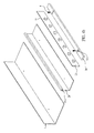
- FIG. 3 is an illustration of a stopping piece of a fixing structure of a LED light bar of a backlight module of a second embodiment of the present invention
- FIG. 4 a is an illustration of a fixing structure of a LED light bar of a backlight module of a third embodiment of the present invention.
- FIG. 4 b is an exploded view of FIG. 4 a.
- a stopping piece with installation holes is added to a conventional structure of a LED light bar, a heat dissipating piece and a back plate; the LED light bar, the heat dissipating piece and the back plate can be fixed together by using fixing elements and the installation holes of the stopping piece, so that troubles and problems caused by having installation holes on the LED light bar can be avoided.
- FIGS. 2 a and 2 b show a fixing structure of a LED light bar of a backlight module of a first embodiment of the present invention, and it mainly comprises: a LED light bar 1 , a heat dissipating piece 2 , a back plate 3 , fixing elements 4 and a stopping piece 5 .
- the LED light bar 1 includes a printed circuit board 12 and a plurality of LEDs 11 evenly disposed on the printed circuit board 12 .
- the heat dissipating piece 2 , the back plate 3 and the stopping piece 5 are in an L-shape, and the heat dissipating piece 2 includes a vertical wall and a horizontal wall.
- the stopping piece 5 includes a vertical portion 51 and a horizontal portion 52 extended and bended horizontally from a bottom end of the vertical portion 51 , a plurality of openings 511 is disposed within the vertical portion 51 , and installation holes 521 are disposed in the horizontal portion 52 .
- a back of the printed circuit board 12 of the LED light bar 1 is disposed against the vertical wall of the heat dissipating piece 2 for heat dissipation, the LEDs 11 on the LED light bar 1 go through the corresponding openings 511 of the stopping piece 5 , and the fixing elements 4 go through the installation holes in the stopping piece 5 to fix the LED light bar 1 on the heat dissipating piece 2 .
- FIG. 3 shows a stopping piece of a fixing structure of a LED light bar of a backlight module of a second embodiment of the present invention.
- the openings 511 within the vertical portion 51 of the stopping piece 5 are through holes surrounded by the vertical portion 51 for the LEDs 11 on the LED light bar 1 to go through correspondingly; while in this embodiment, a stopping piece 5 a includes a vertical portion 51 a and a horizontal portion 52 a extended and bended horizontally from a bottom end of the vertical portion 51 a , and opening 511 a within the vertical portion 51 a are grooves with an opened upper end for the LEDs 11 on the LED light bar 1 to go through correspondingly.
- FIGS. 4 a and 4 b show a fixing structure of a LED light bar of a backlight module of a third embodiment of the present invention.
- the stopping piece 5 includes the vertical portion 51 and the horizontal portion 52 extended and bended horizontally from the bottom end of the vertical portion 51 ; while in this embodiment, a stopping piece 5 b only includes a horizontal portion 51 b , and a heat dissipating piece 2 b further includes a groove 21 b with an opening facing downward disposed at an upper end of a vertical wall.
- the stopping piece 5 b can be structured the same as the L-shaped structure having the through holes or the grooves for the LEDs 11 on the LED light bar 1 to go through correspondingly mentioned in the first and the second embodiments.
- a backlight module of the present invention further comprises a light guide plate (not shown in the figures) to match with the LED light bar 1
- the stopping pieces 5 , 5 a or 5 b can further act as a positioning structure for the light guide plate (not shown in the figures).
- the stopping pieces 5 , 5 a or 5 b can be provided for installations of both the LED light bar 1 and the light guide plate, therefore costs of rivets for positioning of the light guide plate in conventional techniques can further be saved.
Landscapes
- Physics & Mathematics (AREA)
- General Physics & Mathematics (AREA)
- Optics & Photonics (AREA)
- Engineering & Computer Science (AREA)
- Theoretical Computer Science (AREA)
- Microelectronics & Electronic Packaging (AREA)
- Planar Illumination Modules (AREA)
- Liquid Crystal (AREA)
Abstract
Description
Claims (20)
Applications Claiming Priority (4)
| Application Number | Priority Date | Filing Date | Title |
|---|---|---|---|
| CN201110290490XA CN102352990B (en) | 2011-09-28 | 2011-09-28 | Liquid crystal display and backlight module thereof |
| CN201110290490.X | 2011-09-28 | ||
| CN201110290490 | 2011-09-28 | ||
| PCT/CN2011/080655 WO2013044531A1 (en) | 2011-09-28 | 2011-10-11 | Liquid crystal display and backlight module thereof |
Publications (2)
| Publication Number | Publication Date |
|---|---|
| US20130077019A1 US20130077019A1 (en) | 2013-03-28 |
| US8638406B2 true US8638406B2 (en) | 2014-01-28 |
Family
ID=47910937
Family Applications (1)
| Application Number | Title | Priority Date | Filing Date |
|---|---|---|---|
| US13/376,557 Expired - Fee Related US8638406B2 (en) | 2011-09-28 | 2011-10-11 | Backlight module and liquid crystal display device having the same |
Country Status (1)
| Country | Link |
|---|---|
| US (1) | US8638406B2 (en) |
Cited By (2)
| Publication number | Priority date | Publication date | Assignee | Title |
|---|---|---|---|---|
| US20140009922A1 (en) * | 2012-07-04 | 2014-01-09 | Shenzhen China Star Optoelectronics Technology Co., Ltd. | Light-bar adhesion fixture and corresponding light-bar adhesion method |
| US20140233259A1 (en) * | 2013-02-21 | 2014-08-21 | Lg Electronics Inc. | Display device |
Citations (4)
| Publication number | Priority date | Publication date | Assignee | Title |
|---|---|---|---|---|
| US20080180972A1 (en) | 2007-01-31 | 2008-07-31 | Mitsubishi Electric Corporation | Light source device and surface light source device equipped with same |
| JP2008299182A (en) | 2007-06-01 | 2008-12-11 | Hitachi Ltd | Liquid crystal display |
| CN101871596A (en) | 2009-04-23 | 2010-10-27 | 友达光电股份有限公司 | Backlight module and liquid crystal display device |
| US20110141670A1 (en) | 2009-12-16 | 2011-06-16 | Samsung Electronics Co., Ltd. | Backlight unit and display apparatus having the same |
-
2011
- 2011-10-11 US US13/376,557 patent/US8638406B2/en not_active Expired - Fee Related
Patent Citations (4)
| Publication number | Priority date | Publication date | Assignee | Title |
|---|---|---|---|---|
| US20080180972A1 (en) | 2007-01-31 | 2008-07-31 | Mitsubishi Electric Corporation | Light source device and surface light source device equipped with same |
| JP2008299182A (en) | 2007-06-01 | 2008-12-11 | Hitachi Ltd | Liquid crystal display |
| CN101871596A (en) | 2009-04-23 | 2010-10-27 | 友达光电股份有限公司 | Backlight module and liquid crystal display device |
| US20110141670A1 (en) | 2009-12-16 | 2011-06-16 | Samsung Electronics Co., Ltd. | Backlight unit and display apparatus having the same |
Cited By (3)
| Publication number | Priority date | Publication date | Assignee | Title |
|---|---|---|---|---|
| US20140009922A1 (en) * | 2012-07-04 | 2014-01-09 | Shenzhen China Star Optoelectronics Technology Co., Ltd. | Light-bar adhesion fixture and corresponding light-bar adhesion method |
| US20140233259A1 (en) * | 2013-02-21 | 2014-08-21 | Lg Electronics Inc. | Display device |
| US9720269B2 (en) * | 2013-02-21 | 2017-08-01 | Lg Electronics Inc. | Display device |
Also Published As
| Publication number | Publication date |
|---|---|
| US20130077019A1 (en) | 2013-03-28 |
Similar Documents
| Publication | Publication Date | Title |
|---|---|---|
| CN102352990B (en) | Liquid crystal display and backlight module thereof | |
| CN102661558B (en) | Backlight module | |
| CN102681234A (en) | LCD Monitor | |
| US20150268410A1 (en) | Liquid crystal display device | |
| WO2016169182A1 (en) | Display device | |
| US9030642B2 (en) | Liquid crystal display device | |
| KR20120068626A (en) | Led light source module and display device having the same | |
| US9176337B2 (en) | Backlight module | |
| WO2017036100A1 (en) | Backlight module and liquid crystal display device | |
| KR20170024937A (en) | Support assembly for backligh unit, light source module, backlight unit and liquid crystal display device comprising the same | |
| US8638406B2 (en) | Backlight module and liquid crystal display device having the same | |
| KR101021640B1 (en) | Backlight assembly | |
| US20250147360A1 (en) | Backlight Module and Display Device | |
| CN101294670B (en) | Backlight module with swapping type light source system | |
| TW201421123A (en) | Back light module and display device using the same | |
| CN104033788B (en) | Backlight and splicing display device | |
| KR100884660B1 (en) | Backlight Unit of LCD | |
| KR101028294B1 (en) | Optical assembly, backlight unit and display device having same | |
| CN100419538C (en) | Direct type backlight module | |
| WO2024000993A1 (en) | Lamp and light-emitting assembly thereof | |
| US9022634B2 (en) | Backlight and display device | |
| US9823412B2 (en) | Edge type backlight module and liquid crystal display device | |
| US11815710B1 (en) | Backlight module and display device | |
| CN113777820A (en) | Integrated double-backlight display structure | |
| US10338306B2 (en) | Edge-lit light guide device with light source and light guide end received in receiving groove of cover, and metal frame |
Legal Events
| Date | Code | Title | Description |
|---|---|---|---|
| AS | Assignment |
Owner name: SHENZHEN CHINA STAR OPTOELECTRONICS TECHNOLOGY CO. Free format text: ASSIGNMENT OF ASSIGNORS INTEREST;ASSIGNOR:LIANG, SHUO-ZHEN;REEL/FRAME:027347/0765 Effective date: 20111129 |
|
| FEPP | Fee payment procedure |
Free format text: PAYOR NUMBER ASSIGNED (ORIGINAL EVENT CODE: ASPN); ENTITY STATUS OF PATENT OWNER: LARGE ENTITY |
|
| STCF | Information on status: patent grant |
Free format text: PATENTED CASE |
|
| FPAY | Fee payment |
Year of fee payment: 4 |
|
| MAFP | Maintenance fee payment |
Free format text: PAYMENT OF MAINTENANCE FEE, 8TH YEAR, LARGE ENTITY (ORIGINAL EVENT CODE: M1552); ENTITY STATUS OF PATENT OWNER: LARGE ENTITY Year of fee payment: 8 |
|
| FEPP | Fee payment procedure |
Free format text: MAINTENANCE FEE REMINDER MAILED (ORIGINAL EVENT CODE: REM.); ENTITY STATUS OF PATENT OWNER: LARGE ENTITY |
|
| LAPS | Lapse for failure to pay maintenance fees |
Free format text: PATENT EXPIRED FOR FAILURE TO PAY MAINTENANCE FEES (ORIGINAL EVENT CODE: EXP.); ENTITY STATUS OF PATENT OWNER: LARGE ENTITY |
|
| STCH | Information on status: patent discontinuation |
Free format text: PATENT EXPIRED DUE TO NONPAYMENT OF MAINTENANCE FEES UNDER 37 CFR 1.362 |