US8635867B2 - Hydrostatic transmission - Google Patents
Hydrostatic transmission Download PDFInfo
- Publication number
- US8635867B2 US8635867B2 US11/183,177 US18317705A US8635867B2 US 8635867 B2 US8635867 B2 US 8635867B2 US 18317705 A US18317705 A US 18317705A US 8635867 B2 US8635867 B2 US 8635867B2
- Authority
- US
- United States
- Prior art keywords
- housing
- motor
- pump
- hydrostatic transmission
- output shaft
- Prior art date
- Legal status (The legal status is an assumption and is not a legal conclusion. Google has not performed a legal analysis and makes no representation as to the accuracy of the status listed.)
- Active, expires
Links
Images


Classifications
-
- F—MECHANICAL ENGINEERING; LIGHTING; HEATING; WEAPONS; BLASTING
- F04—POSITIVE - DISPLACEMENT MACHINES FOR LIQUIDS; PUMPS FOR LIQUIDS OR ELASTIC FLUIDS
- F04B—POSITIVE-DISPLACEMENT MACHINES FOR LIQUIDS; PUMPS
- F04B1/00—Multi-cylinder machines or pumps characterised by number or arrangement of cylinders
- F04B1/12—Multi-cylinder machines or pumps characterised by number or arrangement of cylinders having cylinder axes coaxial with, or parallel or inclined to, main shaft axis
- F04B1/20—Multi-cylinder machines or pumps characterised by number or arrangement of cylinders having cylinder axes coaxial with, or parallel or inclined to, main shaft axis having rotary cylinder block
- F04B1/2014—Details or component parts
- F04B1/2064—Housings
-
- F—MECHANICAL ENGINEERING; LIGHTING; HEATING; WEAPONS; BLASTING
- F03—MACHINES OR ENGINES FOR LIQUIDS; WIND, SPRING, OR WEIGHT MOTORS; PRODUCING MECHANICAL POWER OR A REACTIVE PROPULSIVE THRUST, NOT OTHERWISE PROVIDED FOR
- F03C—POSITIVE-DISPLACEMENT ENGINES DRIVEN BY LIQUIDS
- F03C1/00—Reciprocating-piston liquid engines
- F03C1/02—Reciprocating-piston liquid engines with multiple-cylinders, characterised by the number or arrangement of cylinders
- F03C1/06—Reciprocating-piston liquid engines with multiple-cylinders, characterised by the number or arrangement of cylinders with cylinder axes generally coaxial with, or parallel or inclined to, main shaft axis
- F03C1/0636—Reciprocating-piston liquid engines with multiple-cylinders, characterised by the number or arrangement of cylinders with cylinder axes generally coaxial with, or parallel or inclined to, main shaft axis having rotary cylinder block
- F03C1/0644—Component parts
- F03C1/0663—Casings, housings
-
- F—MECHANICAL ENGINEERING; LIGHTING; HEATING; WEAPONS; BLASTING
- F16—ENGINEERING ELEMENTS AND UNITS; GENERAL MEASURES FOR PRODUCING AND MAINTAINING EFFECTIVE FUNCTIONING OF MACHINES OR INSTALLATIONS; THERMAL INSULATION IN GENERAL
- F16H—GEARING
- F16H39/00—Rotary fluid gearing using pumps and motors of the volumetric type, i.e. passing a predetermined volume of fluid per revolution
- F16H39/04—Rotary fluid gearing using pumps and motors of the volumetric type, i.e. passing a predetermined volume of fluid per revolution with liquid motor and pump combined in one unit
- F16H39/42—Rotary fluid gearing using pumps and motors of the volumetric type, i.e. passing a predetermined volume of fluid per revolution with liquid motor and pump combined in one unit pump and motor being of different types
Definitions
- the present invention relates generally to hydrostatic transmissions. More particularly, the invention relates to hydrostatic transmissions for use in vehicles, such as mowing machines.
- a typical hydrostatic transmission system includes a variable displacement main hydraulic pump connected in a closed hydraulic circuit with a fixed displacement hydraulic motor.
- the closed hydraulic circuit includes a first conduit connecting the main pump outlet with the motor inlet and a second conduit connecting the motor outlet with a pump inlet. Either of these conduits may be the high pressure line depending upon the direction of pump displacement from neutral.
- the pump is driven by a prime mover, such as an internal combustion engine or an electrical motor, at a certain speed in a certain direction. Changing the displacement of the pump will change its output flow rate, which controls the speed of the motor. Pump outflow can be reversed, thus reversing the direction of the motor.
- the motor is typically generally connected through suitable gearing to the vehicle's wheels or tracks.
- Fluid connections between the pump, motor and conduits should generally be leak free.
- the hoses or other conduits connecting the pump and motor can leak causing a loss of hydraulic fluid and a decrease in transmission performance.
- prior art hydrostatic transmissions were created which generally prevent leakage of fluid from the pump and motor by containing the leakage and returning it to the closed hydraulic circuit as needed.
- these prior art transmissions are typically large, expensive and complex, and often include reduction gearing which further increases the size, cost and complexity of the transmission.
- the present invention provides a compact, integrated hydrostatic transmission without reduction gearing wherein the pump and motor are contained within a single housing, and an output shaft extends from the housing inline with the rotational axis of the motor.
- the output shaft may have a portion thereof forming an axle to which a wheel of a vehicle may be mounted.
- the pump and motor preferably share a common sump within the housing that collects pump and/or motor leakage.
- the invention also provides a unique way of sealing passages between housing parts that eliminates the need for high pressure gaskets at the mating faces of the housing parts.
- the invention provides a hydrostatic transmission comprising a hydraulic pump, an input shaft for rotatably driving the hydraulic pump, an output shaft, a hydraulic motor for driving the output shaft, and a housing enclosing at least a portion of the hydraulic pump and the hydraulic motor.
- the hydraulic pump and hydraulic motor share a common sump within the housing, and the output shaft extends through a wall of the housing in axial alignment with the rotational axis of the pump.
- the hydraulic pump and the hydraulic gear motor to form part of a closed hydraulic loop that further includes at least one passageway formed in the housing.
- the hydraulic pump may be a piston pump and the hydraulic motor may be a gear motor, such as a gerotor.
- the hydraulic motor may be mounted to and carried by a mounting plate that is removably attachable to the housing. The mounting plate permits installation of the motor within the housing as a unit.
- the hydrostatic transmission can be mounted to the frame of a vehicle, and a wheel can be mounted to an outer axle portion of the output shaft of the motor for supporting the vehicle for movement over the ground.
- a hydrostatic transmission including a pump, a motor, and a housing containing at least one of the pump and the motor.
- the housing has first and second mating parts each including a fluid passageway for fluidly connecting the pump and the motor.
- the fluid passageways of the first and second mating parts open to mating faces thereof for receiving a seal insert.
- the seal insert has an insert passageway that extends from an opening at one end of the insert to an opening at the other end of the insert for providing a flow passage therethrough.
- the insert passageway is in communication with the respective passageways of the first and second mating parts, and a sealing element, such as an O-ring, is disposed at each end of the seal insert for sealing an outer diameter of the seal insert to an inner diameter of the passageways of the first and second mating parts.
- a sealing element such as an O-ring
- the fluid passageways in the first and second mating parts may each have counterbores for receiving and axially positioning the seal insert.
- Circumferential recesses may be provided on the outer diameter of the seal insert for retaining the sealing elements.
- a hydrostatic transmission comprising a pump, a motor, and a housing containing the pump and at least a part of the motor.
- the pump includes an input shaft and at least one control member for controlling pump flow output.
- the housing includes opposed side wall portions aligned in a direction parallel to the rotation axis of the input shaft, either one of the side wall portions being selectable to provide thereon a through hole for passage of a rotatable actuating member from the exterior of the housing to the interior of the housing for connecting to the control member.
- the actuating member is mounted for rotation and coupled to the control member for control of the pump flow output.
- Each of the opposed sidewall portions can include a preformed recess in which the through hole can be located, the preformed recess corresponding to a location at which the actuating member can be coupled to the control member for control of the pump.
- the opposed sidewall portions are formed by a common housing part and the control member is a swash block.
- the actuating member is a trunnion shaft.
- a hydrostatic transmission comprising a pump, a motor, and a housing containing the pump and at least a part of the motor.
- the pump includes an input shaft extending from a bottom side of the housing, the input shaft having a drive wheel fixed for rotation therewith and connectable to a prime mover, such as an internal combustion engine.
- the prime mover when coupled to the drive wheel, may have its center of gravity disposed lower than if the drive member was located on an output shaft extending from a top side of the housing.
- the hydrostatic transmission may be mounted in a vehicle along with the prime mover.
- a hydraulic pump assembly comprising a first pump, a second pump, a housing enclosing at least a portion of the first and second pumps, wherein the first and second pumps share a common sump within the housing.
- first and second pumps are connected to first and second motors thereby forming a first and second closed loop.
- At least one positive displacement charge pump is configured to supply fluid drawn from the common sump to the first and second closed loops.
- the common sump serves as a fluid reservoir and the first input shaft and second input shaft are oriented parallel to each other.
- a vehicle comprises a frame, a hydraulic pump including an input shaft and having a housing mounted to the frame with the input shaft extending from the bottom of the housing, and an engine mounted to the frame and coupled to a drive wheel on the input shaft of the motor.
- FIG. 1 is a perspective view of a hydrostatic transmission in accordance with the present invention, wherein an input shaft and an output shaft are oriented at 90 degrees relative to each other.
- FIG. 2 is a side view of the hydrostatic transmission of FIG. 1 .
- FIG. 3 is a top view of the hydrostatic transmission of FIG. 1 .
- FIG. 4 is a front view of a the hydrostatic transmission of FIG. 1 .
- FIG. 5 is a cross-sectional view taken along the line A-A in FIG. 2 .
- FIG. 6 is a cross-sectional view taken along the line B-B in FIG. 2 .
- FIG. 7 is a cross-sectional view taken along the line C-C in FIG. 3 .
- FIG. 8 is a cross-sectional view taken along the line D-D in FIG. 7 .
- FIG. 9 is a cross-sectional view taken along the line E-E in FIG. 4 .
- FIG. 10 is a cross-sectional view taken along the line F-F in FIG. 8 .
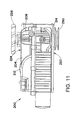
- FIG. 11 is a side view of a hydrostatic transmission in accordance with the present invention, wherein a drive pulley is on an input shaft extending from a bottom side of the housing.
- FIG. 12 a schematic diagram illustrating a vehicle including the hydrostatic transmission of FIG. 11 .
- FIG. 13 is a is a cross-sectional view of another hydrostatic transmission in accordance with the present invention, wherein an input shaft and an output shaft are oriented parallel relative to each other.
- FIG. 14 is a schematic diagram illustrating a hydraulic circuit of a hydraulic pump assembly in accordance with the present invention.
- FIG. 15 is a cross-sectional view of a hydraulic pump assembly in accordance with the present invention.
- the IHT 10 comprises a housing 14 containing a reversible pump 18 fluidly connected to a motor 22 in a closed loop hydraulic circuit.
- An input shaft 26 for driving the pump 18 extends vertically from a top 30 of the housing 14 and includes a fan 34 and pulley 38 .
- the pulley 38 can be connected by a belt to a prime mover, such as an internal combustion engine of a vehicle (not shown), for turning the input shaft 26 .
- An output shaft 42 driven by the motor 22 extends horizontally from a side of the housing 14 .
- the pump 18 supplies pressurized hydraulic fluid to an inlet of the motor 22 for driving the output shaft 42 .
- IHT 10 can be mounted to a frame 43 of a vehicle, generally indicated by reference number 44 , using bolt holes 45 through which bolts can extend to secure the IHT 10 to the vehicle frame 43 .
- a wheel 46 can be mounted to an outer axle portion of the output shaft 42 of the IHT 10 for supporting the vehicle 44 for movement over the ground.
- the output shaft 42 has a tapered portion provided with a key 54 that engages in a key slot in the hub of a wheel 46 so that the wheel 46 will rotate with the output shaft 42 .
- the wheel 46 can be secured in place by means of a nut 58 which is threaded onto the end of the axle output shaft 42 .
- the housing 14 of the IHT 10 includes an upper housing part 62 and a lower housing part 66 secured together with bolts 70 , or by other suitable means.
- a sealing gasket 72 is typically provided at the interface of the upper housing portion 62 and the lower housing portion 66 .
- the upper housing portion 62 and the lower housing portion 66 together form a generally circular opening into which the motor 22 is received.
- the opening is closed by a mounting plate 74 that carries the motor 22 .
- the mounting plate 74 is secured to the upper housing portion 62 and the lower housing portion 66 by bolts 78 , or by other suitable means.
- a sealing gasket 75 ( FIG. 7 ) is provided at the interface of the upper housing portion 62 , the lower housing portion 66 , and the mounting plate 74 .
- the mounting plate 74 may be provided with a bypass valve 76 for creating a short fluid circuit in the motor 22 to allow free rotation of the output shaft 42 when desired.
- the upper housing portion 62 , the lower housing portion 66 , and the mounting plate 74 together form a sealed interior space of the housing 14 that contains the motor 18 and pump 22 .
- the interior of the housing 14 serves as a shared sump for the motor 22 and the pump 18 , and further may function as a reservoir.
- the housing 14 further includes cooling fins 82 at various locations, generally on the top surface 30 near the fan 34 , for assisting in dissipating heat generated during operation of the pump 18 and motor 22 of the IHT 10 .
- the housing 14 can further include an externally mounted oil filter 86 for filtering the hydraulic fluid of the IST 10 .
- the externally mounted oil filter 86 can be easily accessed for replacement when the filter becomes dirty.
- a breather 90 is provided for allowing air to exit and enter the housing 14 as necessary to compensate for thermal expansion and contraction of the hydraulic fluid.
- the breather 90 can also function as a fill cap for adding hydraulic fluid to the shared sump.
- a drain plug can be included at the bottom of the housing 14 for draining the hydraulic fluid so that fresh hydraulic fluid can be added to the housing 14 .
- FIG. 5 is a cross-sectional view of the pump portion of the IHT 10 showing the pump 18 and input shaft 26 .
- the pump 18 is a variable flow reversible piston pump.
- the input shaft 26 is supported in the upper housing portion 62 by a bearing 92 , and a seal 94 is provided to seal the shaft 26 to the housing 14 to prevent fluid from escaping from the interior of the housing 14 .
- a cylinder barrel 95 having a plurality of pistons 96 mounted for reciprocal movement therein is coupled to the input shaft 26 for rotation therewith.
- the input shaft 26 extends through a swash-block 97 which serves as a control member for controlling pump flow output.
- a thrust bearing 98 supports the input shaft 26 below the swash block 97 .
- the swash block 97 is arranged such that the pistons 96 of the cylinder barrel 95 abut its upper surface.
- the swash block 97 is connected by a linkage to an actuating member which in the illustrated embodiment is a trunnion shaft 99 ( FIG. 1 ).
- an actuating member which in the illustrated embodiment is a trunnion shaft 99 ( FIG. 1 ).
- Trunnion shaft 99 protrudes from the housing 14 through a hole 100 in the lower housing part 66 (linkage and trunnion shaft 99 not shown in FIG. 5 ).
- the hole 100 can be preformed in the lower housing part 66 , or may be bored as desired.
- the swash block 97 can be inclined in both directions from its neutral point, or zero-inclination (the horizontal plane in FIG. 5 ). Rotation of the trunnion shaft 99 in one direction inclines the swash block 97 such that the pump 18 pumps fluid in a first direction, while rotation of the trunnion shaft 99 in the opposite direction inclines the swash block 97 such that the pump 18 pumps fluid in the opposite direction.
- suitable control means can be connected to the trunnion shaft 99 for allowing an operator of a vehicle to rotate the trunnion shaft 99 as desired.
- the lower housing part 66 of the IHT 10 includes opposing side wall portions 101 and 102 .
- the trunnion shaft 99 can extend from the side wall 102 of the housing 14 as shown, or alternatively may extend from the opposing side 101 of the housing 14 .
- two trunnion shafts (and corresponding linkages) can be provided, each trunnion shaft extending from an opposite side wall 101 and 102 of the housing 14 .
- a preformed recess such as recess 103 in the illustrated embodiment, can be provided in which a through hole can be located if desired.
- the location of the preformed recesses can correspond to a location at which the actuating member, once installed in the through-hole, can be coupled to the control member for control of the pump.
- pressurized fluid is supplied to the motor 22 from the pump 18 via passageways formed in the upper housing member 62 and the mounting plate 74 .
- a first passageway between the pump 18 and the motor 22 begins at pump pressure port 104 .
- Pump pressure port 104 connects to a passageway 106 in the upper housing member 62 as seen in FIG. 5 .
- Passageway 106 connects to passageway 108 which in turn connects to passageway 110 .
- Passageway 110 connects to passageway 112 in the mounting plate 74 , as best seen in FIGS. 8 and 9 .
- passageway 114 connects to a pressure port of the motor 22 (not shown).
- a second passageway between the pump 18 and motor 22 begins at pump pressure port 105 .
- Pump pressure port 105 connects to passageway 116 in the upper housing member 62 .
- Passageway 116 connects to passageway 118 , which in turn connects to passageway 120 in the mounting plate 74 , as seen in FIGS. 8 and 9 .
- Passageway 120 connects to passageway 122 which in turn connects to passageway 124 and thereby to the other pressure port of the motor 22 , as seen in FIG. 10 .
- a closed loop hydraulic circuit is formed between the pump 18 and the motor 22 by the first and second passageways.
- seal inserts 130 and 134 are provided for sealing the connections between fluid passageways 110 and 112 in the lower housing part 66 , and fluid passageways 118 and 120 in the upper housing part 62 , respectively.
- the seal inserts 130 and 134 include passageways 138 and 142 that extend from an opening at one end of the seal inserts 130 and 134 to an opening at the other end of the seal inserts 130 and 134 for providing a flow passage therethrough.
- Counterbores 146 are provided in the faces of the mating surfaces of the upper housing portion 62 and the mounting plate 74 for receiving and axially positioning the seal inserts 130 and 134 .
- Sealing elements such as O-rings 150 are disposed at each end of the seal inserts 130 and 134 for sealing an outer diameter of the seal inserts 130 and 134 to an inner diameter of the respective passageways formed in the upper housing portion 62 and the mounting plate 74 .
- the O-rings 150 are retained in circumferential notches at the terminal ends of the seal inserts 130 and 134 .
- the O-rings could be retained in circumferential recesses in the outer diameter of the seal inserts 130 and 134 .
- the seal inserts 130 and 134 described above can be utilized in other applications for sealing a fluid connection between mating housing parts.
- the prime mover (not shown) drives the input shaft 26 via pulley 38 which in turn rotatably drives the pump 18 .
- the hydraulic pump supplies hydraulic fluid via either the first or second passageways to the motor 22 , depending on the direction of rotation of the trunnion 99 .
- the motor 22 in turn drives the output shaft 42 .
- the pump 18 and motor 22 of the present invention share a common sump 154 within the housing 14 .
- the common sump 154 in the illustrated embodiment is formed by interior surfaces of the upper housing member 62 , the lower housing member 66 , and the mounting plate 74 . Fluid leakage from the hydraulic circuit drains to the common sump 154 where it can be returned to the closed loop as make-up flow to replenish the fluid in the closed circuit.
- a charge pump 158 may be provided for supplying fluid drawn from the sump 154 to the closed loop.
- the charge pump 158 is a positive displacement pump also driven by the input shaft 26 .
- a charge pump inlet line 162 formed in the lower housing member 66 is connected via filter 86 to the common sump 154 .
- a charge pump outlet passage 170 also formed in the lower housing member 66 is connected to pump pressure ports 104 and 105 via check valves 174 and 178 , as best seen in FIG. 9 .
- the charge pump 158 supplies a steady flow of hydraulic fluid to the pump return line.
- the charge pump 158 runs continuously whenever the input shaft 26 is being driven by the prime mover.
- the charge pump 158 includes a pressure release bypass valve 182 and bypass passageway 186 for bypassing flow from the outlet passageway 170 to the inlet passageway 162 when the pressure in the outlet passageway 170 exceeds a predetermined level.
- the charge pump 158 functions not only to maintain a desired operating volume of hydraulic fluid in the closed loop, but also to circulate the fluid between the sump 154 and the closed loop to facilitate cooling of the hydraulic fluid.
- the charge pump 158 also distributes hydraulic fluid to the bearing 92 for cooling and lubrication.
- the fluid supplied to the bearing 92 also drains to the common sump 154 .
- an IHT 200 comprising a housing 204 containing a reversible pump 208 fluidly connected to a motor 212 in a closed loop hydraulic circuit.
- An input shaft 214 for driving the pump 218 extends vertically through a bottom side 222 and a top side 224 of the housing 204 .
- the input shaft 214 includes a fan 226 on the portion thereof extending from the top side 224 of the housing 204 .
- the input shaft 214 also includes drive wheel, such as a pulley 230 , fixed for rotation therewith on the portion thereof extending from the bottom side 222 of the housing 204 .
- the pulley 230 can be connected by a belt to a prime mover, such as an internal combustion engine of a vehicle (not shown), for turning the input shaft 214 to drive the pump 208 .
- IHT 200 the external and internal details of IHT 200 are identical to the IHT 10 described above in FIGS. 1-10 , with the exception of input shaft 214 extending through a bottom surface 222 of the housing 204 .
- the IHT 200 facilitates mounting of the prime mover such that its center of gravity may be disposed lower than if the pulley 230 was located on the portion of the input shaft 214 extending from the top side 224 of the housing 204 .
- FIG. 12 a schematic diagram of a vehicle 250 including the IHT 200 is shown.
- the vehicle 250 which may be a lawn mower, includes an engine 254 having a vertically aligned output shaft 256 extending downwardly from the bottom of the engine 254 and coupled to the pulley 230 mounted on the input shaft 216 of the IHT 200 by a belt 258 .
- a sprocket can be substituted for the pulley 230 and a chain can be provided to couple the IHT 200 and the engine 254 .
- the pulley 230 and output shaft 256 generally should be aligned in a horizontal plane, by providing the pulley 230 below the IHT 200 , the engine 254 can be located at a lower position than if the pulley 230 was located on an input shaft 216 extending from a top side 224 of the housing 204 .
- the IHT 200 enables the overall center of gravity of the vehicle 250 to be lower which thereby can make the vehicle 250 more stable.
- the IHT 300 is similar in all general aspects to the IHT 10 described above, with the exception of the input shaft 310 and output shaft 320 being oriented parallel to each other.
- the input shaft 310 and output shaft 320 extend from opposite sides of the housing 330 . It will be appreciated that other configurations are possible, such as the input shaft 310 and output shaft 320 being parallel and extending from a common side of the housing 330 .
- FIG. 14 a schematic diagram is shown illustrating a simplified fluid circuit 350 of a hydraulic pump assembly 355 in accordance with the present invention.
- the fluid circuit 350 includes a first pump 358 and a second pump 362 .
- the first and second pumps 358 and 362 are connected in closed hydraulic loops 363 and 364 , respectively, via pressure lines to first and second motors 366 and 370 for supply and return of fluid.
- the pump assembly 355 also includes a common sump 374 for collecting any leakage from the first and second pumps 358 and 362 .
- a charge pump 378 is provided for supplying fluid drawn from the common sump 374 to the closed loops 363 and 364 .
- a filter 382 can be provided as shown to filter the fluid drawn from the common sump 374 .
- the charge pump 378 supplies flow to closed loop 363 via check valves 384 and 385 , and to closed loop 364 via check valves 386 and 387 . It will be appreciated that the arrangement of check valves permits flow of fluid from the charge pump 378 to the closed loops 363 and 364 only when the pressure in one of the lines of the closed loops drops below a predetermined pressure.
- the first and second pumps 358 and 362 of the hydraulic pump assembly 355 are contained within a housing 400 .
- the pumps 358 and 362 in the illustrated embodiment are identical to the pump 18 as described above. However, it will be appreciated that a variety of different types of pumps may be used as desired.
- the pumps 358 and 362 can be connected via conventional porting and pressure lines to externally located hydraulic motors for the supply and return of pressurized fluid. It will be appreciated that the pumps 358 and 362 , when connected to motors, are connected in first and second closed hydraulic loops, each hydraulic loop including a pump, a motor, and supply and return lines as described in relation to FIG. 14 .
- the interior of the housing 400 serves as the shared sump 374 for both pumps 358 and 362 , and further may function as a reservoir. As such, any leakage from the pumps 358 and 362 is collected in the shared sump 374 where it can be returned to the first and second closed loops as make-up flow.
- each pump 358 and 362 includes a charge pump 408 and 412 as for supplying fluid drawn from the shared sump 374 to the first and second closed loops in the manner described above in connection with the IHT 10 of FIGS. 1-10 .
- fluid is drawn from the shared sump 374 through the filter 382 into a charge pump inlet line 432 .
- the fluid is then pumped by the charge pumps 408 and 412 into a charge pump outlet line 436 and supplied to the pressure return line of the closed loops for providing makeup flow thereto.
- only one charge pump may be provided for supplying fluid drawn from the sump to the first and second closed loops.
- the two pumps 358 and 362 can be driven separately by connecting each pump separately to one or more prime movers, such as internal combustion engines.
- the pump assembly 355 can also be provided with a single input, double output mechanism such as bevel gears or spur gears to thereby drive both input shafts together.
Landscapes
- Engineering & Computer Science (AREA)
- General Engineering & Computer Science (AREA)
- Mechanical Engineering (AREA)
- Chemical & Material Sciences (AREA)
- Combustion & Propulsion (AREA)
- Motor Power Transmission Devices (AREA)
Abstract
Description
Claims (16)
Priority Applications (1)
| Application Number | Priority Date | Filing Date | Title |
|---|---|---|---|
| US11/183,177 US8635867B2 (en) | 2004-07-15 | 2005-07-15 | Hydrostatic transmission |
Applications Claiming Priority (2)
| Application Number | Priority Date | Filing Date | Title |
|---|---|---|---|
| US58812504P | 2004-07-15 | 2004-07-15 | |
| US11/183,177 US8635867B2 (en) | 2004-07-15 | 2005-07-15 | Hydrostatic transmission |
Publications (2)
| Publication Number | Publication Date |
|---|---|
| US20060039801A1 US20060039801A1 (en) | 2006-02-23 |
| US8635867B2 true US8635867B2 (en) | 2014-01-28 |
Family
ID=35909800
Family Applications (1)
| Application Number | Title | Priority Date | Filing Date |
|---|---|---|---|
| US11/183,177 Active 2027-10-07 US8635867B2 (en) | 2004-07-15 | 2005-07-15 | Hydrostatic transmission |
Country Status (1)
| Country | Link |
|---|---|
| US (1) | US8635867B2 (en) |
Cited By (6)
| Publication number | Priority date | Publication date | Assignee | Title |
|---|---|---|---|---|
| US8925311B1 (en) * | 2009-07-24 | 2015-01-06 | Hydro-Gear Limited Partnership | Transmission and engine configuration |
| US9677574B1 (en) * | 2013-09-12 | 2017-06-13 | Hydro-Gear Limited Partnership | Transmission assembly |
| US10465354B2 (en) | 2016-12-15 | 2019-11-05 | Caterpillar Inc. | Hydraulic fluid systems for machine implements |
| US10794459B1 (en) * | 2018-05-02 | 2020-10-06 | Parker-Hannifin Corporation | Hydrostatic transmission |
| US10859148B1 (en) * | 2018-05-03 | 2020-12-08 | Parker-Hannifin Corporation | Modular porting manifold and motor end cover for hydrostatic transmission |
| US11708831B1 (en) * | 2021-09-23 | 2023-07-25 | Parker-Hannifin Corporation | Debris exclusion seal guard for a pump |
Families Citing this family (14)
| Publication number | Priority date | Publication date | Assignee | Title |
|---|---|---|---|---|
| US8635867B2 (en) | 2004-07-15 | 2014-01-28 | Parker-Hannifin Corporation | Hydrostatic transmission |
| US7520346B2 (en) * | 2005-10-20 | 2009-04-21 | Parker-Hannifin Corporation | Hydraulic power unit |
| US20070137918A1 (en) * | 2005-11-23 | 2007-06-21 | Xingen Dong | Mounting of hydrostatic transmission for riding lawn mower |
| US20080120974A1 (en) * | 2006-11-24 | 2008-05-29 | Parker-Hannifin Corporation | Integrated hydrostatic transmission for left and right wheel drive |
| DE102006058355A1 (en) * | 2006-03-10 | 2007-09-13 | Brueninghaus Hydromatik Gmbh | Combi pump housing for several nominal sizes |
| JP2008105573A (en) | 2006-10-26 | 2008-05-08 | Kanzaki Kokyukoki Mfg Co Ltd | Wheel motor device |
| US9114703B1 (en) | 2009-04-24 | 2015-08-25 | Hydro-Gear Limited Partnership | Modular transmission assembly |
| US8613342B2 (en) * | 2009-10-13 | 2013-12-24 | GXi Holdings, LLC | Hydraulic drive system for motorized power equipment |
| US8857171B2 (en) * | 2010-02-11 | 2014-10-14 | Parker-Hannifin Corporation | Integrated hydrostatic transmission |
| US8997480B1 (en) | 2010-03-30 | 2015-04-07 | Hydro-Gear Limited Partnership | Drive assembly and transmission |
| FR2965020B1 (en) * | 2010-09-17 | 2012-10-12 | Poclain Hydraulics Ind | HYDRAULIC DEVICE |
| US9435324B2 (en) * | 2012-05-10 | 2016-09-06 | Parker-Hannifin Corporation | Electro-hydraulic drive system |
| US9151374B2 (en) * | 2013-06-17 | 2015-10-06 | Parker-Hannifin Corporation | Hydrostatic transmission with integrated pump and motor |
| FR3010764B1 (en) * | 2013-09-19 | 2016-02-12 | Poclain Hydraulics Ind | ASSEMBLY COMBINING GAVAGE FUNCTIONS AND TANK IN A HYDRAULIC MACHINE CASE |
Citations (107)
| Publication number | Priority date | Publication date | Assignee | Title |
|---|---|---|---|---|
| US2495685A (en) | 1945-06-08 | 1950-01-31 | Beaman Bernard | Two-stage hydraulic pressure pump |
| US2834297A (en) * | 1953-02-12 | 1958-05-13 | Vickers Inc | Power transmission |
| US2936589A (en) * | 1954-12-28 | 1960-05-17 | Gerotor May Corp Of Maryland | Hydraulic transmission |
| US2988007A (en) * | 1954-12-28 | 1961-06-13 | Gerotor May Corp | Hydraulic transmission |
| US3090456A (en) | 1961-04-04 | 1963-05-21 | Fairchild Stratos Corp | Electrically powered wheel |
| US3177665A (en) | 1963-11-20 | 1965-04-13 | Sundstrand Corp | Hydrostatic transmission |
| US3485315A (en) * | 1967-08-30 | 1969-12-23 | Harley E Bergren | Hydrostatic transmission and controls therefor |
| US3493067A (en) | 1967-09-15 | 1970-02-03 | Houdaille Industries Inc | Direct drive wheel mount |
| US3643434A (en) * | 1969-07-23 | 1972-02-22 | Bosch Gmbh Robert | Hydraulic apparatus with axially aligned hydraulic units |
| US3864916A (en) * | 1972-09-25 | 1975-02-11 | Renault | Hydrostatic transmissions for motor vehicles |
| US3890783A (en) * | 1974-04-01 | 1975-06-24 | Cmi Corp | Dual pressure control assembly |
| US3949824A (en) | 1973-02-23 | 1976-04-13 | Joshua Shaw & Sons Limited | Drive arrangements for mechanical handling vehicles |
| US4064766A (en) * | 1977-06-15 | 1977-12-27 | Caterpillar Tractor Co. | Modular control linkage assembly for a hydrostatic transmission |
| US4070219A (en) * | 1974-08-12 | 1978-01-24 | F. D. Farnam Co. | Method of making densified convolute gasket structure |
| US4071106A (en) | 1974-01-14 | 1978-01-31 | Caterpillar Tractor Co. | Auxiliary hydrostatic wheel drive |
| US4105369A (en) | 1977-06-30 | 1978-08-08 | Owatonna Tool Company | Two-stage pump |
| US4171559A (en) * | 1976-10-21 | 1979-10-23 | Stratoflex, Inc. | Method of making connections in pneumatic and hydraulic systems and testing such systems |
| GB2062187A (en) | 1979-11-06 | 1981-05-20 | Hammond Eng Ltd | Hydrostatic transmission unit |
| US4285643A (en) | 1978-05-08 | 1981-08-25 | White Harvey C | Rotary fluid pressure device |
| US4373600A (en) | 1980-07-18 | 1983-02-15 | Veda, Inc. | Three wheel drive vehicle |
| US4580646A (en) | 1983-12-20 | 1986-04-08 | Kabushiki Kaisha Komatsu Seisakusho | Motor mounting apparatus in a hydrostatically driven vehicle |
| US4616478A (en) * | 1981-10-30 | 1986-10-14 | Falle Jensen | Rotatable hydrostatic transmission |
| US4627237A (en) * | 1984-03-30 | 1986-12-09 | Sundstrand Corporation | Hydrostatic transmission with fixed fluid capacity ratio between pump and motor |
| US4666091A (en) | 1982-09-03 | 1987-05-19 | Heide Hans Von Der | Pickup and delivery truck for silage, straw and similar material |
| US4843817A (en) | 1987-11-18 | 1989-07-04 | Shivvers, Inc. | Integrated hydraulic transmission |
| US4845949A (en) | 1987-11-18 | 1989-07-11 | Shivvers, Inc. | Parking brake for integrated transmission |
| US4870820A (en) * | 1987-04-15 | 1989-10-03 | Kanzaki Kokyukoki Mfg. Co. Ltd. | HST (hydro-static-transmission) system driving speed changing apparatus |
| JPH01300073A (en) | 1988-05-27 | 1989-12-04 | Hitachi Ltd | Air cooled/oil supply type compressor |
| US4903792A (en) | 1986-09-30 | 1990-02-27 | Ze Ying Tan | Hydraulic motors and vehicle hydrostatic transmission system of wheel motor type |
| US4936095A (en) * | 1988-10-28 | 1990-06-26 | Eaton Corporation | Hydrostatic transmission system and power limiter control therefor |
| US5018351A (en) * | 1987-12-16 | 1991-05-28 | Gerhard Klemm Maschinenfabrik Gmbh & Co. | Hydromechanical drive |
| US5046994A (en) * | 1989-11-20 | 1991-09-10 | Kanzaki Kokyukoki Mfg. Co., Ltd. | Vehicle transmission assembly |
| US5181837A (en) * | 1991-04-18 | 1993-01-26 | Vickers, Incorporated | Electric motor driven inline hydraulic apparatus |
| US5203169A (en) | 1990-12-25 | 1993-04-20 | Kanzaki Kokyukoki Mfg. Co., Ltd. | Axle drive apparatus |
| US5205123A (en) * | 1990-09-06 | 1993-04-27 | Dunstan Phillip E | Infinitely variable differential hydrostatic transmission |
| US5317936A (en) * | 1991-09-19 | 1994-06-07 | Kanzaki Kokyukoki Mfg. Co. Ltd. | Power transmission structure of a working car |
| US5356347A (en) * | 1992-10-23 | 1994-10-18 | Honda Giken Kokyo Kabushiki Kaisha | Hydrostatic continuously variable transmission |
| US5363740A (en) | 1993-07-16 | 1994-11-15 | Pneumo Abex Corporation | Fluid motor/pump with scavenged case |
| US5373697A (en) * | 1991-07-22 | 1994-12-20 | Tecumseh Products Company | Hydraulic fluid system and dump valve mechanism for a hydrostatic transaxle |
| US5394699A (en) | 1993-05-25 | 1995-03-07 | Kanzaki Kokyukoki Mfg. Co., Ltd. | Axle driving apparatus |
| US5396768A (en) * | 1994-01-10 | 1995-03-14 | Caterpillar Inc. | Gearless hydro-mechanical transmission |
| US5473964A (en) | 1988-02-03 | 1995-12-12 | Kanzaki Kokyukoki Mfg. Co., Ltd. | Axle driving apparatus |
| US5497623A (en) * | 1991-07-09 | 1996-03-12 | Hydro-Gear Limited Partnership | Hydrostatic pump and motor unit |
| US5540563A (en) | 1994-09-16 | 1996-07-30 | Sauer Inc. | Unitary housing for double hydraulic unit |
| US5557931A (en) * | 1995-02-24 | 1996-09-24 | Hydro-Gear Limited, Limited Partnership | Charge pump for axle driving apparatus including hydrostatic transmission |
| US5622051A (en) | 1995-06-26 | 1997-04-22 | Kanzaki Kokyukoki Mfg. Co., Ltd. | Axle driving apparatus with cooling tubing |
| US5910060A (en) | 1998-03-05 | 1999-06-08 | Blume; David B. | Transmission |
| US5918691A (en) | 1994-05-23 | 1999-07-06 | Kanzaki Kokyokoki Mfg. Co., Ltd. | Axle driving apparatus |
| US5921151A (en) * | 1989-03-03 | 1999-07-13 | Sauer Inc. | Axle driving apparatus |
| US5979270A (en) * | 1997-07-09 | 1999-11-09 | Unipat Ag | Hydrostatic transaxle |
| US6010423A (en) * | 1998-08-18 | 2000-01-04 | Tecumseh Products Company | Reversible variable speed transmission and transaxle having pressure compensating flow metering device |
| US6030182A (en) * | 1996-03-19 | 2000-02-29 | Eaton Corporation | Variable displacement pump and optional manual or remote control system therefor |
| US6073443A (en) | 1997-08-06 | 2000-06-13 | Kanzaki Kokyukoki Mfg. Co., Ltd. | Axle driving apparatus |
| USRE36807E (en) * | 1988-10-07 | 2000-08-08 | Kanzaki Kokyukoki Mfg. Co., Ltd. | Axle driving apparatus |
| US6152247A (en) | 1997-07-25 | 2000-11-28 | Hydro-Gear Limited Partnership | Zero turn transaxle |
| US6167619B1 (en) | 1997-11-15 | 2001-01-02 | Blissfield Manufacturing Company | Method for assembling a heat exchanger |
| US6176086B1 (en) | 1998-12-10 | 2001-01-23 | Sauer Inc. | Hydrostatic transmission in one housing |
| US6209928B1 (en) * | 1998-06-04 | 2001-04-03 | The Regents Of The University Of California | Microfluidic interconnects |
| US6220377B1 (en) * | 1998-04-17 | 2001-04-24 | Lansberry Tractor Company, Inc. | Load support shifting vehicle |
| JP2001220770A (en) | 2000-02-10 | 2001-08-17 | Hitachi Constr Mach Co Ltd | Construction machine |
| US6276840B1 (en) | 1995-12-22 | 2001-08-21 | Stratos Lightwave, Inc. | Massive parallel optical interconnect system |
| US6324962B1 (en) * | 2000-04-10 | 2001-12-04 | Crary Company | Valve block mounting arrangement |
| US6343471B1 (en) * | 2000-04-03 | 2002-02-05 | Hydro-Thoma Limited | Hydrostatic transmissions and transaxles |
| US6363815B1 (en) * | 1998-04-15 | 2002-04-02 | Kanzaki Kokyukoki Mfg. Co., Ltd. | Transmission mechanism of vehicle with HST |
| US6425244B1 (en) * | 1999-10-18 | 2002-07-30 | Kanzaki Kokyukoki Mfg. Co., Ltd. | Pump unit |
| US6427443B2 (en) * | 1995-02-24 | 2002-08-06 | Hydro-Gear Limited Partnership | Charge pump manifold for hydrostatic transmissions and integrated hydrostatic transaxles |
| US6477838B1 (en) * | 1998-03-31 | 2002-11-12 | Hydro-Thoma Limited | Hydrostatic machines for use in transmission and transaxle product |
| US6481203B1 (en) * | 1999-06-10 | 2002-11-19 | Tecumseh Products Company | Electric shifting of a variable speed transmission |
| US6487857B1 (en) | 2001-02-20 | 2002-12-03 | Hydro-Gear Limited Partnership | Zero-turn transaxle with mounted return to neutral mechanism |
| US6487856B1 (en) * | 1999-10-18 | 2002-12-03 | Kanzaki Kokyukoki Mfg. Co., Ltd. | Tandem pump unit |
| US20020179340A1 (en) | 2001-05-04 | 2002-12-05 | Jolliff Norman E. | Modular hydrostatic transaxle for zero turn radius mower |
| US6508059B1 (en) * | 1999-10-26 | 2003-01-21 | Kanzaki Kokyukoki Mfg. Co., Ltd. | Hydrostatic transmission |
| US6543560B1 (en) * | 2000-07-18 | 2003-04-08 | Delta Systems, Inc. | Hydrostatic transmission with integral actuator |
| US20030070429A1 (en) | 2001-08-21 | 2003-04-17 | Jolliff Norman E. | Hydrostatic transmission |
| US6554084B1 (en) | 1999-05-07 | 2003-04-29 | Tcm Corporation | Hydraulically driven forklift |
| US20030116936A1 (en) | 2001-12-26 | 2003-06-26 | Felsing Brian E. | Skid steer loader suspension |
| US6592336B1 (en) | 1999-04-22 | 2003-07-15 | Yuken Kogyo Kabushiki Kaisha | Hydraulic pump with a built-in electric motor |
| US6592290B2 (en) | 2000-10-11 | 2003-07-15 | Multiquip, Inc. | Power trowel gearbox |
| US6598694B2 (en) | 2000-02-14 | 2003-07-29 | Linde Aktiengesellschaft | Hub drive |
| US6643959B2 (en) * | 2000-02-23 | 2003-11-11 | Tecumseh Products Company | Implement having engine and transaxle module |
| US6672058B1 (en) * | 2003-01-13 | 2004-01-06 | Hydro-Gear Limited Partnership | Zero turn transaxle |
| US6672843B1 (en) * | 2002-04-08 | 2004-01-06 | Hydro-Gear Limited Partnership | Dual pump apparatus comprising dual drive shafts and auxiliary pump |
| US6675696B1 (en) | 2001-12-14 | 2004-01-13 | Hydro-Gear Limited Partnership | Pump and center section for hydrostatic transmission |
| US6688417B2 (en) | 2001-10-09 | 2004-02-10 | Sauer-Danfoss Inc. | Axial piston unit for integrated wheel hub |
| US6694729B1 (en) * | 1999-07-16 | 2004-02-24 | Hydro-Gear Limited Partnership | Pump |
| US20040126279A1 (en) * | 2002-08-02 | 2004-07-01 | Renzi Ronald F. | Portable apparatus for separating sample and detecting target analytes |
| US6779421B2 (en) * | 2001-05-15 | 2004-08-24 | Hydro-Thoma Limited | Hydrostatic transmission with internal fluid expansion chamber |
| US6799346B2 (en) | 2002-01-04 | 2004-10-05 | Atico International Usa, Inc. | Toothbrush with oppositely reciprocating brush heads |
| US6804958B1 (en) | 2000-08-11 | 2004-10-19 | Hydro-Gear Limited Partnership | Hydrostatic transmission bypass latch |
| US6817960B2 (en) * | 1999-02-09 | 2004-11-16 | Tecumseh Products Company | Hydrostatic transaxle having axial piston motor and method for manufacturing transaxles |
| US6843056B1 (en) | 2003-01-13 | 2005-01-18 | Hydro-Gear Limited Partnership | Zero turn transaxle |
| US6953327B1 (en) | 2003-03-11 | 2005-10-11 | Hydro-Gear Limited Partnership | Dual pump |
| US6955046B1 (en) | 2002-11-07 | 2005-10-18 | Hydro-Gear Limited Partnership | System and method for electronic actuation of axle driving apparatus |
| US6973783B1 (en) * | 2004-02-27 | 2005-12-13 | Hydro-Gear Limited Partnership | Zero turn drive apparatus |
| US6988580B2 (en) | 2002-04-03 | 2006-01-24 | Ryota Ohashi | Pump unit and working vehicle |
| US20060039801A1 (en) | 2004-07-15 | 2006-02-23 | Xingen Dong | Hydrostatic transmission |
| US7036311B2 (en) | 1991-07-09 | 2006-05-02 | Hydro-Gear Limited Partnership | Hydrostatic transmission |
| US7056101B1 (en) | 2002-06-19 | 2006-06-06 | Hydro-Gear Limited Partnership | Inline tandem pump |
| US7082759B1 (en) | 2004-09-02 | 2006-08-01 | Michio Tsukamoto | Hydraulic drive vehicle |
| US7137250B1 (en) | 2004-03-08 | 2006-11-21 | Hydro-Gear Limited Partnership | Zero turn drive apparatus with power take off |
| US20070017712A1 (en) | 2005-07-21 | 2007-01-25 | Dunn James T | Tractor with hydraulic speed and steering control for steering at maximum speed |
| US7309301B2 (en) | 2005-10-21 | 2007-12-18 | Ford Global Technologies, Llc | Transaxle having a differential mechanism and on-demand transfer clutch |
| US7308790B1 (en) | 2004-09-30 | 2007-12-18 | Hydro-Gear Limited Partnership | Adjustable hydraulic motor apparatus |
| US7316287B2 (en) | 2004-04-13 | 2008-01-08 | Kanzaki Kokyukoki Mfg. Co., Ltd. | Hydraulic pump unit, hydraulic pump set, and working vehicle |
| US7370714B2 (en) | 2003-04-17 | 2008-05-13 | Toshifumi Yasuda | Power-dividing device and axle-driving device for a working vehicle |
| US7455132B2 (en) | 2005-04-29 | 2008-11-25 | Parker-Hannifin Corporation | Hydraulic axle combination |
| US7455144B2 (en) | 2002-10-15 | 2008-11-25 | Kanzaki Kokyukoki Mfg. Co., Ltd. | Hydraulic transaxle apparatus with flexible ports |
-
2005
- 2005-07-15 US US11/183,177 patent/US8635867B2/en active Active
Patent Citations (117)
| Publication number | Priority date | Publication date | Assignee | Title |
|---|---|---|---|---|
| US2495685A (en) | 1945-06-08 | 1950-01-31 | Beaman Bernard | Two-stage hydraulic pressure pump |
| US2834297A (en) * | 1953-02-12 | 1958-05-13 | Vickers Inc | Power transmission |
| US2936589A (en) * | 1954-12-28 | 1960-05-17 | Gerotor May Corp Of Maryland | Hydraulic transmission |
| US2988007A (en) * | 1954-12-28 | 1961-06-13 | Gerotor May Corp | Hydraulic transmission |
| US3090456A (en) | 1961-04-04 | 1963-05-21 | Fairchild Stratos Corp | Electrically powered wheel |
| US3177665A (en) | 1963-11-20 | 1965-04-13 | Sundstrand Corp | Hydrostatic transmission |
| US3485315A (en) * | 1967-08-30 | 1969-12-23 | Harley E Bergren | Hydrostatic transmission and controls therefor |
| US3493067A (en) | 1967-09-15 | 1970-02-03 | Houdaille Industries Inc | Direct drive wheel mount |
| US3643434A (en) * | 1969-07-23 | 1972-02-22 | Bosch Gmbh Robert | Hydraulic apparatus with axially aligned hydraulic units |
| US3864916A (en) * | 1972-09-25 | 1975-02-11 | Renault | Hydrostatic transmissions for motor vehicles |
| US3949824A (en) | 1973-02-23 | 1976-04-13 | Joshua Shaw & Sons Limited | Drive arrangements for mechanical handling vehicles |
| US4071106A (en) | 1974-01-14 | 1978-01-31 | Caterpillar Tractor Co. | Auxiliary hydrostatic wheel drive |
| US3890783A (en) * | 1974-04-01 | 1975-06-24 | Cmi Corp | Dual pressure control assembly |
| US4070219A (en) * | 1974-08-12 | 1978-01-24 | F. D. Farnam Co. | Method of making densified convolute gasket structure |
| US4171559A (en) * | 1976-10-21 | 1979-10-23 | Stratoflex, Inc. | Method of making connections in pneumatic and hydraulic systems and testing such systems |
| US4064766A (en) * | 1977-06-15 | 1977-12-27 | Caterpillar Tractor Co. | Modular control linkage assembly for a hydrostatic transmission |
| US4105369A (en) | 1977-06-30 | 1978-08-08 | Owatonna Tool Company | Two-stage pump |
| US4285643A (en) | 1978-05-08 | 1981-08-25 | White Harvey C | Rotary fluid pressure device |
| GB2062187A (en) | 1979-11-06 | 1981-05-20 | Hammond Eng Ltd | Hydrostatic transmission unit |
| US4373600A (en) | 1980-07-18 | 1983-02-15 | Veda, Inc. | Three wheel drive vehicle |
| US4616478A (en) * | 1981-10-30 | 1986-10-14 | Falle Jensen | Rotatable hydrostatic transmission |
| US4666091A (en) | 1982-09-03 | 1987-05-19 | Heide Hans Von Der | Pickup and delivery truck for silage, straw and similar material |
| US4580646A (en) | 1983-12-20 | 1986-04-08 | Kabushiki Kaisha Komatsu Seisakusho | Motor mounting apparatus in a hydrostatically driven vehicle |
| US4627237A (en) * | 1984-03-30 | 1986-12-09 | Sundstrand Corporation | Hydrostatic transmission with fixed fluid capacity ratio between pump and motor |
| US4903792A (en) | 1986-09-30 | 1990-02-27 | Ze Ying Tan | Hydraulic motors and vehicle hydrostatic transmission system of wheel motor type |
| US4870820A (en) * | 1987-04-15 | 1989-10-03 | Kanzaki Kokyukoki Mfg. Co. Ltd. | HST (hydro-static-transmission) system driving speed changing apparatus |
| US4843817A (en) | 1987-11-18 | 1989-07-04 | Shivvers, Inc. | Integrated hydraulic transmission |
| US4845949A (en) | 1987-11-18 | 1989-07-11 | Shivvers, Inc. | Parking brake for integrated transmission |
| US5018351A (en) * | 1987-12-16 | 1991-05-28 | Gerhard Klemm Maschinenfabrik Gmbh & Co. | Hydromechanical drive |
| US5473964A (en) | 1988-02-03 | 1995-12-12 | Kanzaki Kokyukoki Mfg. Co., Ltd. | Axle driving apparatus |
| US5950500A (en) * | 1988-02-03 | 1999-09-14 | Kanzaki Kokyukoki Mfg. Co., Ltd. | Axle driving apparatus |
| JPH01300073A (en) | 1988-05-27 | 1989-12-04 | Hitachi Ltd | Air cooled/oil supply type compressor |
| USRE36807E (en) * | 1988-10-07 | 2000-08-08 | Kanzaki Kokyukoki Mfg. Co., Ltd. | Axle driving apparatus |
| US4936095A (en) * | 1988-10-28 | 1990-06-26 | Eaton Corporation | Hydrostatic transmission system and power limiter control therefor |
| US5921151A (en) * | 1989-03-03 | 1999-07-13 | Sauer Inc. | Axle driving apparatus |
| US5046994A (en) * | 1989-11-20 | 1991-09-10 | Kanzaki Kokyukoki Mfg. Co., Ltd. | Vehicle transmission assembly |
| US5205123A (en) * | 1990-09-06 | 1993-04-27 | Dunstan Phillip E | Infinitely variable differential hydrostatic transmission |
| US5203169A (en) | 1990-12-25 | 1993-04-20 | Kanzaki Kokyukoki Mfg. Co., Ltd. | Axle drive apparatus |
| US5181837A (en) * | 1991-04-18 | 1993-01-26 | Vickers, Incorporated | Electric motor driven inline hydraulic apparatus |
| US6550243B2 (en) | 1991-07-09 | 2003-04-22 | Hydro-Gear Limited Partnership | Hydrostatic transmission |
| US5497623A (en) * | 1991-07-09 | 1996-03-12 | Hydro-Gear Limited Partnership | Hydrostatic pump and motor unit |
| US7036311B2 (en) | 1991-07-09 | 2006-05-02 | Hydro-Gear Limited Partnership | Hydrostatic transmission |
| US5373697A (en) * | 1991-07-22 | 1994-12-20 | Tecumseh Products Company | Hydraulic fluid system and dump valve mechanism for a hydrostatic transaxle |
| US5317936A (en) * | 1991-09-19 | 1994-06-07 | Kanzaki Kokyukoki Mfg. Co. Ltd. | Power transmission structure of a working car |
| US5356347A (en) * | 1992-10-23 | 1994-10-18 | Honda Giken Kokyo Kabushiki Kaisha | Hydrostatic continuously variable transmission |
| US5394699A (en) | 1993-05-25 | 1995-03-07 | Kanzaki Kokyukoki Mfg. Co., Ltd. | Axle driving apparatus |
| US5363740A (en) | 1993-07-16 | 1994-11-15 | Pneumo Abex Corporation | Fluid motor/pump with scavenged case |
| US5396768A (en) * | 1994-01-10 | 1995-03-14 | Caterpillar Inc. | Gearless hydro-mechanical transmission |
| US5918691A (en) | 1994-05-23 | 1999-07-06 | Kanzaki Kokyokoki Mfg. Co., Ltd. | Axle driving apparatus |
| US5540563A (en) | 1994-09-16 | 1996-07-30 | Sauer Inc. | Unitary housing for double hydraulic unit |
| US5557931A (en) * | 1995-02-24 | 1996-09-24 | Hydro-Gear Limited, Limited Partnership | Charge pump for axle driving apparatus including hydrostatic transmission |
| US6427443B2 (en) * | 1995-02-24 | 2002-08-06 | Hydro-Gear Limited Partnership | Charge pump manifold for hydrostatic transmissions and integrated hydrostatic transaxles |
| US5622051A (en) | 1995-06-26 | 1997-04-22 | Kanzaki Kokyukoki Mfg. Co., Ltd. | Axle driving apparatus with cooling tubing |
| US6276840B1 (en) | 1995-12-22 | 2001-08-21 | Stratos Lightwave, Inc. | Massive parallel optical interconnect system |
| US6030182A (en) * | 1996-03-19 | 2000-02-29 | Eaton Corporation | Variable displacement pump and optional manual or remote control system therefor |
| US6427442B2 (en) * | 1997-07-09 | 2002-08-06 | Hydro-Thoma Limited | Hydrostatic transaxle |
| US6564550B2 (en) * | 1997-07-09 | 2003-05-20 | Hydro-Thoma Limited | Hydrostatic transaxle |
| US5979270A (en) * | 1997-07-09 | 1999-11-09 | Unipat Ag | Hydrostatic transaxle |
| US6237332B1 (en) * | 1997-07-09 | 2001-05-29 | Unipat Ag | Hydrostatic transaxle |
| US6152247A (en) | 1997-07-25 | 2000-11-28 | Hydro-Gear Limited Partnership | Zero turn transaxle |
| US6073443A (en) | 1997-08-06 | 2000-06-13 | Kanzaki Kokyukoki Mfg. Co., Ltd. | Axle driving apparatus |
| US6233929B1 (en) | 1997-08-06 | 2001-05-22 | Kanzaki Kokyukoki Mfg. Co., Ltd. | Axle driving apparatus |
| US6167619B1 (en) | 1997-11-15 | 2001-01-02 | Blissfield Manufacturing Company | Method for assembling a heat exchanger |
| US5910060A (en) | 1998-03-05 | 1999-06-08 | Blume; David B. | Transmission |
| US6477838B1 (en) * | 1998-03-31 | 2002-11-12 | Hydro-Thoma Limited | Hydrostatic machines for use in transmission and transaxle product |
| US6363815B1 (en) * | 1998-04-15 | 2002-04-02 | Kanzaki Kokyukoki Mfg. Co., Ltd. | Transmission mechanism of vehicle with HST |
| US6220377B1 (en) * | 1998-04-17 | 2001-04-24 | Lansberry Tractor Company, Inc. | Load support shifting vehicle |
| US6209928B1 (en) * | 1998-06-04 | 2001-04-03 | The Regents Of The University Of California | Microfluidic interconnects |
| US6010423A (en) * | 1998-08-18 | 2000-01-04 | Tecumseh Products Company | Reversible variable speed transmission and transaxle having pressure compensating flow metering device |
| US6176086B1 (en) | 1998-12-10 | 2001-01-23 | Sauer Inc. | Hydrostatic transmission in one housing |
| US6817960B2 (en) * | 1999-02-09 | 2004-11-16 | Tecumseh Products Company | Hydrostatic transaxle having axial piston motor and method for manufacturing transaxles |
| US6592336B1 (en) | 1999-04-22 | 2003-07-15 | Yuken Kogyo Kabushiki Kaisha | Hydraulic pump with a built-in electric motor |
| US6554084B1 (en) | 1999-05-07 | 2003-04-29 | Tcm Corporation | Hydraulically driven forklift |
| US6481203B1 (en) * | 1999-06-10 | 2002-11-19 | Tecumseh Products Company | Electric shifting of a variable speed transmission |
| US6694729B1 (en) * | 1999-07-16 | 2004-02-24 | Hydro-Gear Limited Partnership | Pump |
| US6736605B2 (en) | 1999-10-18 | 2004-05-18 | Kanzaki Kokyukoki Mfg. Co., Ltd. | Tandem pump unit |
| US6425244B1 (en) * | 1999-10-18 | 2002-07-30 | Kanzaki Kokyukoki Mfg. Co., Ltd. | Pump unit |
| US6487856B1 (en) * | 1999-10-18 | 2002-12-03 | Kanzaki Kokyukoki Mfg. Co., Ltd. | Tandem pump unit |
| US6508059B1 (en) * | 1999-10-26 | 2003-01-21 | Kanzaki Kokyukoki Mfg. Co., Ltd. | Hydrostatic transmission |
| JP2001220770A (en) | 2000-02-10 | 2001-08-17 | Hitachi Constr Mach Co Ltd | Construction machine |
| US6598694B2 (en) | 2000-02-14 | 2003-07-29 | Linde Aktiengesellschaft | Hub drive |
| US6643959B2 (en) * | 2000-02-23 | 2003-11-11 | Tecumseh Products Company | Implement having engine and transaxle module |
| US6343471B1 (en) * | 2000-04-03 | 2002-02-05 | Hydro-Thoma Limited | Hydrostatic transmissions and transaxles |
| US6324962B1 (en) * | 2000-04-10 | 2001-12-04 | Crary Company | Valve block mounting arrangement |
| US6543560B1 (en) * | 2000-07-18 | 2003-04-08 | Delta Systems, Inc. | Hydrostatic transmission with integral actuator |
| US6804958B1 (en) | 2000-08-11 | 2004-10-19 | Hydro-Gear Limited Partnership | Hydrostatic transmission bypass latch |
| US6592290B2 (en) | 2000-10-11 | 2003-07-15 | Multiquip, Inc. | Power trowel gearbox |
| US6715284B1 (en) | 2001-02-20 | 2004-04-06 | Hydro-Gear Limited Partnership | Zero-turn transaxle with mounted return to neutral mechanism |
| US6487857B1 (en) | 2001-02-20 | 2002-12-03 | Hydro-Gear Limited Partnership | Zero-turn transaxle with mounted return to neutral mechanism |
| US6782797B1 (en) | 2001-02-20 | 2004-08-31 | Hydro-Gear Limited Partnership | Hydraulic apparatus with return to neutral mechanism |
| US20020179340A1 (en) | 2001-05-04 | 2002-12-05 | Jolliff Norman E. | Modular hydrostatic transaxle for zero turn radius mower |
| US6779421B2 (en) * | 2001-05-15 | 2004-08-24 | Hydro-Thoma Limited | Hydrostatic transmission with internal fluid expansion chamber |
| US20030070429A1 (en) | 2001-08-21 | 2003-04-17 | Jolliff Norman E. | Hydrostatic transmission |
| US6688417B2 (en) | 2001-10-09 | 2004-02-10 | Sauer-Danfoss Inc. | Axial piston unit for integrated wheel hub |
| US6675696B1 (en) | 2001-12-14 | 2004-01-13 | Hydro-Gear Limited Partnership | Pump and center section for hydrostatic transmission |
| US20030116936A1 (en) | 2001-12-26 | 2003-06-26 | Felsing Brian E. | Skid steer loader suspension |
| US6799346B2 (en) | 2002-01-04 | 2004-10-05 | Atico International Usa, Inc. | Toothbrush with oppositely reciprocating brush heads |
| US6988580B2 (en) | 2002-04-03 | 2006-01-24 | Ryota Ohashi | Pump unit and working vehicle |
| US6672843B1 (en) * | 2002-04-08 | 2004-01-06 | Hydro-Gear Limited Partnership | Dual pump apparatus comprising dual drive shafts and auxiliary pump |
| US7056101B1 (en) | 2002-06-19 | 2006-06-06 | Hydro-Gear Limited Partnership | Inline tandem pump |
| US20040126279A1 (en) * | 2002-08-02 | 2004-07-01 | Renzi Ronald F. | Portable apparatus for separating sample and detecting target analytes |
| US7455144B2 (en) | 2002-10-15 | 2008-11-25 | Kanzaki Kokyukoki Mfg. Co., Ltd. | Hydraulic transaxle apparatus with flexible ports |
| US6955046B1 (en) | 2002-11-07 | 2005-10-18 | Hydro-Gear Limited Partnership | System and method for electronic actuation of axle driving apparatus |
| US6843056B1 (en) | 2003-01-13 | 2005-01-18 | Hydro-Gear Limited Partnership | Zero turn transaxle |
| US6672058B1 (en) * | 2003-01-13 | 2004-01-06 | Hydro-Gear Limited Partnership | Zero turn transaxle |
| US6953327B1 (en) | 2003-03-11 | 2005-10-11 | Hydro-Gear Limited Partnership | Dual pump |
| US7370714B2 (en) | 2003-04-17 | 2008-05-13 | Toshifumi Yasuda | Power-dividing device and axle-driving device for a working vehicle |
| US6973783B1 (en) * | 2004-02-27 | 2005-12-13 | Hydro-Gear Limited Partnership | Zero turn drive apparatus |
| US7392654B1 (en) | 2004-02-27 | 2008-07-01 | Hydro-Gear Limited Partnership | Zero turn drive apparatus |
| US7137250B1 (en) | 2004-03-08 | 2006-11-21 | Hydro-Gear Limited Partnership | Zero turn drive apparatus with power take off |
| US7316287B2 (en) | 2004-04-13 | 2008-01-08 | Kanzaki Kokyukoki Mfg. Co., Ltd. | Hydraulic pump unit, hydraulic pump set, and working vehicle |
| US20060039801A1 (en) | 2004-07-15 | 2006-02-23 | Xingen Dong | Hydrostatic transmission |
| US7082759B1 (en) | 2004-09-02 | 2006-08-01 | Michio Tsukamoto | Hydraulic drive vehicle |
| US7308790B1 (en) | 2004-09-30 | 2007-12-18 | Hydro-Gear Limited Partnership | Adjustable hydraulic motor apparatus |
| US7455132B2 (en) | 2005-04-29 | 2008-11-25 | Parker-Hannifin Corporation | Hydraulic axle combination |
| US20070017712A1 (en) | 2005-07-21 | 2007-01-25 | Dunn James T | Tractor with hydraulic speed and steering control for steering at maximum speed |
| US7309301B2 (en) | 2005-10-21 | 2007-12-18 | Ford Global Technologies, Llc | Transaxle having a differential mechanism and on-demand transfer clutch |
Non-Patent Citations (12)
| Title |
|---|
| Brochure; "The Latest from Hydro-Gear"; date unknown. |
| Brochure; "TRW Ross Gear Torqdrive Axle"; Sep. 2003. |
| Notice of Allowance for U.S. Appl. No. 11/467,375, dated Dec. 19, 2008. |
| Notice of Allowance for U.S. Appl. No. 11/536,358, dated Aug. 3, 2009. |
| Notice of Allowance for U.S. Appl. No. 11/551,524, dated Dec. 9, 2008. |
| Office Action for U.S. Appl. No. 11/467,375, dated Jun. 24, 2008. |
| Office Action for U.S. Appl. No. 11/536,358, dated Aug. 6, 2008. |
| Office Action for U.S. Appl. No. 11/536,358, dated Mar. 24, 2009. |
| Office Action for U.S. Appl. No. 11/551,524, dated Jul. 22, 2008. |
| Office Action for U.S. Appl. No. 11/563,122, dated Mar. 31, 2009. |
| Office Action for U.S. Appl. No. 11/761,651, dated Apr. 13, 2009. |
| Supplemental Notice of Allowance for U.S. Appl. No. 11/536,358, dated Aug. 21, 2009. |
Cited By (9)
| Publication number | Priority date | Publication date | Assignee | Title |
|---|---|---|---|---|
| US8925311B1 (en) * | 2009-07-24 | 2015-01-06 | Hydro-Gear Limited Partnership | Transmission and engine configuration |
| US9726269B1 (en) | 2009-07-24 | 2017-08-08 | Hydro-Gear Limited Partnership | Transmission and engine configuration |
| US10364874B1 (en) | 2009-07-24 | 2019-07-30 | Hydro-Gear Limited Partnership | Transmission and engine configuration |
| US9677574B1 (en) * | 2013-09-12 | 2017-06-13 | Hydro-Gear Limited Partnership | Transmission assembly |
| US10288156B1 (en) | 2013-09-12 | 2019-05-14 | Hydro-Gear Limited Partnership | Transmission assembly |
| US10465354B2 (en) | 2016-12-15 | 2019-11-05 | Caterpillar Inc. | Hydraulic fluid systems for machine implements |
| US10794459B1 (en) * | 2018-05-02 | 2020-10-06 | Parker-Hannifin Corporation | Hydrostatic transmission |
| US10859148B1 (en) * | 2018-05-03 | 2020-12-08 | Parker-Hannifin Corporation | Modular porting manifold and motor end cover for hydrostatic transmission |
| US11708831B1 (en) * | 2021-09-23 | 2023-07-25 | Parker-Hannifin Corporation | Debris exclusion seal guard for a pump |
Also Published As
| Publication number | Publication date |
|---|---|
| US20060039801A1 (en) | 2006-02-23 |
Similar Documents
| Publication | Publication Date | Title |
|---|---|---|
| US8635867B2 (en) | Hydrostatic transmission | |
| US7566207B1 (en) | Dual pump transmission | |
| US7886534B2 (en) | Integrated hydrostatic transmission assembly | |
| US6843056B1 (en) | Zero turn transaxle | |
| US6672058B1 (en) | Zero turn transaxle | |
| US6884195B2 (en) | Hydrostatic transaxle | |
| US7229256B1 (en) | Dual pump transmission | |
| US7185577B2 (en) | Tandem pump unit | |
| US6705840B1 (en) | Inline tandem pump | |
| US7918088B1 (en) | Dual pump assembly | |
| US8215109B1 (en) | Dual pump apparatus with power take off | |
| US8857171B2 (en) | Integrated hydrostatic transmission | |
| US8151927B2 (en) | Wheel motor device | |
| US7328576B1 (en) | Zero turn transaxle | |
| US9151374B2 (en) | Hydrostatic transmission with integrated pump and motor | |
| US20060090639A1 (en) | Hydraulic piston pump unit with integral fluid reservoir | |
| US6343471B1 (en) | Hydrostatic transmissions and transaxles | |
| US20030070429A1 (en) | Hydrostatic transmission | |
| US7520346B2 (en) | Hydraulic power unit | |
| US7225617B1 (en) | Bypass mechanism for a hydraulic drive apparatus | |
| US7523611B2 (en) | Hydrostatic transmission with external manifold | |
| US11662016B1 (en) | Transmission pump adapter manifold for hydrostatic transmission |
Legal Events
| Date | Code | Title | Description |
|---|---|---|---|
| AS | Assignment |
Owner name: PARKER-HANNIFIN CORPORATION, OHIO Free format text: ASSIGNMENT OF ASSIGNORS INTEREST;ASSIGNORS:DONG, XINGEN;ACHARYA, BARUN;HOLZSCHUH, FRANK P.;REEL/FRAME:016731/0017 Effective date: 20050816 |
|
| STCF | Information on status: patent grant |
Free format text: PATENTED CASE |
|
| FPAY | Fee payment |
Year of fee payment: 4 |
|
| AS | Assignment |
Owner name: PARKER INTANGIBLES, LLC, OHIO Free format text: ASSIGNMENT OF ASSIGNORS INTEREST;ASSIGNOR:PARKER-HANNIFIN CORPORATION;REEL/FRAME:045843/0859 Effective date: 20180405 |
|
| MAFP | Maintenance fee payment |
Free format text: PAYMENT OF MAINTENANCE FEE, 8TH YEAR, LARGE ENTITY (ORIGINAL EVENT CODE: M1552); ENTITY STATUS OF PATENT OWNER: LARGE ENTITY Year of fee payment: 8 |
|
| MAFP | Maintenance fee payment |
Free format text: PAYMENT OF MAINTENANCE FEE, 12TH YEAR, LARGE ENTITY (ORIGINAL EVENT CODE: M1553); ENTITY STATUS OF PATENT OWNER: LARGE ENTITY Year of fee payment: 12 |