US5373697A - Hydraulic fluid system and dump valve mechanism for a hydrostatic transaxle - Google Patents
Hydraulic fluid system and dump valve mechanism for a hydrostatic transaxle Download PDFInfo
- Publication number
- US5373697A US5373697A US07/733,452 US73345291A US5373697A US 5373697 A US5373697 A US 5373697A US 73345291 A US73345291 A US 73345291A US 5373697 A US5373697 A US 5373697A
- Authority
- US
- United States
- Prior art keywords
- valve means
- disposed
- pump
- motor
- hydrostatic
- Prior art date
- Legal status (The legal status is an assumption and is not a legal conclusion. Google has not performed a legal analysis and makes no representation as to the accuracy of the status listed.)
- Expired - Fee Related
Links
Images


Classifications
-
- B—PERFORMING OPERATIONS; TRANSPORTING
- B60—VEHICLES IN GENERAL
- B60K—ARRANGEMENT OR MOUNTING OF PROPULSION UNITS OR OF TRANSMISSIONS IN VEHICLES; ARRANGEMENT OR MOUNTING OF PLURAL DIVERSE PRIME-MOVERS IN VEHICLES; AUXILIARY DRIVES FOR VEHICLES; INSTRUMENTATION OR DASHBOARDS FOR VEHICLES; ARRANGEMENTS IN CONNECTION WITH COOLING, AIR INTAKE, GAS EXHAUST OR FUEL SUPPLY OF PROPULSION UNITS IN VEHICLES
- B60K17/00—Arrangement or mounting of transmissions in vehicles
- B60K17/04—Arrangement or mounting of transmissions in vehicles characterised by arrangement, location, or kind of gearing
- B60K17/10—Arrangement or mounting of transmissions in vehicles characterised by arrangement, location, or kind of gearing of fluid gearing
- B60K17/105—Units comprising at least a part of the gearing and a torque-transmitting axle, e.g. transaxles
Definitions
- Hydrostatic transmissions transmit rotary mechanical motion, typically from an internal combustion engine, to fluid motion, then back to rotary mechanical motion to rotate a drive axle in order to drive a vehicle, such as a lawn and garden tractor.
- the hydrostatic transmission regulates or controls the output rotary mechanical motion such that varying output speeds in the forward and reverse directions are possible with a single speed input rotary mechanical motion.
- a cylinder unit having a pump and motor rotates on a fixed pintle with pistons positioned within the cylinders and attached to slippers mounted in an expander band so that as the cylinder unit rotates, the pistons are driven by the slippers which engage the surrounding eccentric annular track ring of the pump and motor.
- hydrostatic transmission One common application of a hydrostatic transmission is within a riding lawn mower. Although lawn mowers are self-propelled, in many situations such as positioning the mower in a garage or because of engine failure, it is necessary to manually push the mower. Hydraulic transmissions however, present a special problem when the vehicle is to be manually moved. With gear transmissions a neutral mode or position is achieved by mechanically disengaging the input shaft from the output shaft by either disengaging the gears coupling the input shaft to the output shaft or disengaging the output shaft from the gears. Thus it is possible to manually move the vehicle without resistance from the transmission system either from the output shaft or the input shaft since they are disengaged from one another.
- oil that circulates through the transaxle housing must be free from particulates or foreign matter before reentering the pintle, as the pistons of the pump and motor can be damaged during operation by particulates suspended in the oil as the pistons reciprocate.
- the present invention in one form thereof, provides in a hydrostatic transmission a transmission disengagement mechanism constituting a simplified, two piece dump valve actuating assembly.
- the present invention in another form thereof, provides a settling area in the transaxle housing transmission chamber, external to the hydrostatic transmission unit, with projections upwardly jutting from the bottom of the transaxle housing that trap particulates suspended in the oil as the oil circulates.
- the projections thus act as particulate traps.
- the settling chamber may include a magnet, mounted to the inside of the transaxle casing, for attracting and permanently holding magnetic particles or debris that become suspended in the oil and circulated into the settling area.
- the invention in still another form thereof, provides a double lip seal radially disposed on the output shaft that operably connects the motor with the gear assembly, the output shaft extending between the transmission chamber and the gearing chamber.
- An inverted W-shaped resilient seal is retained onto the output shaft by retainers and springs.
- the present invention provides a hydrostatic transmission comprising a housing having a first part and a second part mating with each other at an interface and defining an internal cavity and a chamber, a pump having a plurality of displaceable pistons, a motor having a plurality of displaceable pistons, a hydraulic circuit fluidly connecting the pump with the motor, valve means for providing selective communication between the hydraulic circuit and the chamber, an actuator trapped between the first part and the second part and positioned to unseat the valve means when urged in contact with the valve means, and an operator actuated control rod means for urging the actuator against the valve means.
- the relief valve actuator assembly including a plate-like member having two protrusions extending into the relief valve openings in contact with the ball valves, the plate-like member having an aperture in which is transversely disposed a rotating actuator rod with an eccentric portion to urge the plate-like member axially inwardly unseating the ball valves.
- FIG. 3 is a sectional view of the track ring capturing arrangement in accordance with a preferred embodiment of the present invention.
- FIG. 5 is an enlarged fragmentary sectional view of the control guide assembly
- FIG. 6 is an end view of the control guide
- FIG. 6A is an elevational view of the control guide
- FIG. 8 is an enlarged sectional view of the dump valve assembly taken along line 8--8 of FIG. 1;
- FIG. 10 is a plan view of the input drive coupling
- FIG. 11 is a bottom view of the fan
- FIG. 12 is a top view of the fan
- FIG. 13 is a fragmentary plan view of the upper transaxle housing over the input drive portion depicting the cast-in cooling vanes;
- FIG. 14 is an elevational view of the pump track ring pivot pin
- FIG. 15 is an enlarged fragmentary view of the dashed circular portion of FIG. 1 showing the connection of the pivot pin;
- FIG. 16 is an enlarged fragmentary view of the oil seal.
- Corresponding reference characters indicate corresponding parts throughout the several views.
- the exemplifications set out herein illustrate a preferred embodiment of the invention, in one form thereof, and such exemplifications are not to be construed as limiting the scope of the invention in any manner.
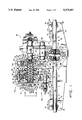
- HST 20 includes a hydraulic or hydrostatic unit 21 housed in a lower transaxle casing 22 having bolt holes 23, the hydrostatic unit 21 including a pump 24 and motor 26, being described in detail hereinbelow, for transferring rotary motion from an energy source such as an internal combustion engine (not shown) to the drive wheels of a vehicle (not shown) in which the HST 20 is installed.
- the drive wheels (not shown) are drivingly connected to the hydrostatic unit 21 through a succession of gearing beginning with an output member 28 axially connected to motor 26 so as to rotate therewith.
- Output member 28 is drivingly connected to an output shaft 30 seated in the transaxle casing of which only lower transaxle casing 22 is shown in FIG. 1, while pinion gear 36 is disposed on output shaft 30 which meshes with an output gear 37 disposed on a transfer shaft 38 supported by bearings 40 and 41.
- a transfer gear 42 Disposed on transfer shaft 38 is a transfer gear 42 imparting its rotational energy to differential 44 for driving right and left axle shafts 46 and 47 each respectively supported in lower transaxle casing 22 by right and left axle bearings 48 and 49.
- Differential 44 includes a ring gear 50 meshed with transfer gear 42, a transverse shaft 51 and bevel gears 52, 53, 54, and 55, which are drivingly connected to right axle shaft 46 and left axle shaft 47.
- an oil chamber 56 Surrounding differential 44 and the gearing is an oil chamber 56, which is separated from the chamber for the hydrostatic unit 21, and serves as a reservoir of oil to lubricate the differential 44.
- the motor 26 rotates, the motion is transferred to the axle shafts 46 and 47 to turn the wheels (not shown) attached thereto in order to drive the vehicle.
- the oil chamber 56 is separate from the hydrostatic unit 21, it is necessary to ensure that the oil from oil chamber 56 does not mix with the oil in the hydrostatic unit 21 to avoid contamination of this hydrostatic oil.
- the double-lipped oil seal 31 is essentially W-shaped having two lips 34 and 35 which are urged into contact with the surface of output shaft 30 by annular spring clip 32 and annular retainers 33.
- the retainers 33 hold lips 34 and 35 against shaft 30 while spring clip 32 urges the bowed center portion 39 inwardly.
- the double-lipped construction of oil seal 31 thus prevents the flow of oil from the differential side of the transaxle to the hydrostatic unit side, and vice versa.
- the hydrostatic unit 21, as mentioned above, is driven by an external energy source such as an internal combustion engine (not shown) and, referring to FIG. 2, is generally connected to the hydrostatic transmission 20 via a belt (not shown) from an output shaft of the internal combustion engine to a pulley 58.
- the pulley 58 depicted in FIG. 9, has an input drive shaft bore 74 that allows input drive shaft 60 to extend therethrough and is drivingly connected thereto by a nut 59 threaded onto the input drive shaft 60 which also extends through a bore 62 in the upper transaxle casing 64 (see FIG.
- pulley 58 forms part of an external transaxle cooling system which, in cooperation with a fan 76 (FIGS. 11 and 12), a drive coupling 78 (FIG. 10), and external helical fins 80 (see FIG. 13) on the upper transaxle casing 64, all of which are described in detail hereinbelow, provides a continuous, helical air flow pattern that smoothly and unimpededly flows over the hydrostatic transmission 20 effecting cooling thereof with minimal air turbulence, since the fins 80 being curved in the same direction as the air flow pattern produced by the fan 76 act in mutual cooperation.
- the drive coupling 78 axially downwardly of pulley 58 is the drive coupling 78 likewise disposed or splined on input drive shaft 60 extending through an input drive shaft bore 82 of the drive coupling 78, and axially downwardly of drive coupling 78 is the fan 76 also disposed on input drive shaft 60 extending through an input drive shaft bore 84 of the fan 76.
- the drive coupling 78 is connected to input drive shaft 60 so as to be rotatable therewith.
- Bolt apertures 88 are located at the apexes of the equilateral triangular shaped drive coupling 78 while bolt apertures 86, and 90 each form the apexes of an equilateral triangle that correspond with the shape of drive coupling 78.
- the drive coupling 78 is triangular shaped to correspond with a triangular shaped hub portion 94 in the center of fan 76 forming a semi-locking driving fit between the drive coupling 78 and fan 76.
- the fan 76 has three different shapes of outer fan blades X, Y, and Z, which axially extend from the top to the bottom of the fan 76 such that rotation of the fan 76 on input drive shaft 60 causes air to be drawn downwardly towards the hydrostatic transaxle 20, then outwardly.
- Blades X, Y, and Z also radially extend from the outer periphery 100 to an inner radius 102 for an extension distance that is approximately 1/3 of the total radius of the fan 76.
- Extending from the inner radius 102 to the triangular shaped hub portion 94 are fan ribs 104 that also axially extend from the top to the bottom of the fan 76 and act to direct the inflowing air downwardly toward external fins 80.
- three elements namely the air apertures 96 and 98, the blades X, Y, and Z, and the fan ribs 104 cooperatively serve to draw air into the fan 76 and create a helical air flow pattern which spreads downwardly and outwardly over the external fins 80 formed in the transaxle upper casing 64, while the radial shape of the external fins 80 correspond to the rotational direction of the helical air flow pattern to permit smooth and efficient cooling of the hydrostatic transaxle 20 by allowing the air to flow without impediment or created air turbulence that would retard or hinder the constant flow pattern created by the fan 76.
- the hydraulic unit 21 of the hydrostatic transaxle 20 includes a pump 24, driven by the input system described above, which in turn drives the motor 26, both the pump and motor 26 being mounted on a fixed conduit in the form of pintle 72.
- the pintle 72 comprises two passageways or conduits 106 and 107 each having a spring 108 and 109 disposed therein which retain ball valves 110 and 111 adjacent seats 119 and 121 of plugs 112 and 113 threaded into one end of the pintle, each defining discharge ports 115 and 117.
- ball valves 110 and 111 normally close discharge ports 115 and 117 during operating condition due to the pressure exerted within pintle 72, except when make-up oil is needed, and this maintains a closed pressure system between the pump 24, the motor 26, and pintle 72.
- Radially outwardly surrounding pintle 72 is pump 24 (in FIG. 1 being on the left side) and motor 26 (in FIG. 1 being on the right side).
- a cylinder such as pump cylinder 70, being applicable to both the pump 24 and motor 26 of the hydrostatic unit 21, is rotatable on pintle 72 and has a plurality of bores (not shown) in which are disposed a plurality of pistons (e.g. pump piston 134 and motor piston 116) that axially reciprocate within the bores and radially rotate with respect to the pintle 72.
- the cylinders thus rotate around pintle 72 and within their respective track ring, described hereinbelow, while the respective pistons pump fluid through rotating action of the cylinder as in the case of pump 24, or are pumped by fluid pressure flowing through pintle passageways 106 and 107 of pintle 72 as in the case of motor 26.
- the pump 24 and motor 26 form a closed fluid path being in communication with each other via the pintle 72 and its pintle passageways 106 and 107, the fluid flowing from the action of the rotating pistons 134 of the pump 24 into the pistons 116 of the motor 26 causing the motor to rotate output member 28 being attached to the motor cylinder 71.
- Motor 26 comprises a motor track ring 114 radially surrounding a plurality of pistons 116 having corresponding slippers 118, of which only one of each is shown, the slippers 118 disposed radially adjacent to the inner radius 120 of motor track ring 114.
- the pistons 116 with their slippers 118 are rotatable around pintle 72 within the motor track ring 114 and are in fluid communication with the pintle tubes 106 and 107 via motor pintle ports 122 and 123.
- the motor track ring 114 is fixed eccentrically relative to the pintle 72 so that the pistons 116 reciprocate radially and rotate.
- the motor track ring 114 includes radially extending lug portions 124 and 125 which fit into recesses 126 and 127 cast into the lower transaxle casing 22.
- the upper transaxle casing 64 being attached to the lower transaxle casing 22, includes, radially adjacent the lug portions 124 and 125, bolt apertures 128 and 129 through which bolts 128 and 129 extend to thereby clampingly fix the motor track ring 114 between the upper and lower transaxle housings 64 and 22.
- the elimination of a pin or rod extending through the transaxle 20 to retain or fix the motor track ring 114 shortens the overall axial length of the transaxle and permits drive train gearing to be closer to the motor 26.
- recesses could be formed in both housing halves 22 and 64, or in only the upper half 64.
- Other techniques could be used to clamp track ring 114 other than lugs 124 and 125.
- pump 24 radially surrounds pintle 72 and comprises a pump track ring 132 surrounding a plurality of pistons 134 having corresponding slippers 136, of which only one of each is shown, the slippers 136 disposed radially adjacent to the inner radius 138 of pump track ring 132.
- the pistons 134 with their slippers 136 are rotatable around pintle 72 within the pump track ring 132 and are in fluid communication with the pintle tubes 106 and 107 via pump pintle ports 140 and 141.
- Pump track ring 132 is not fixed relative to pintle 72 as is motor track ring 114 although pump 24 is eccentric relative to pintle 72 as is motor 26.
- the pump track ring 132 eccentrically pivots around the pintle 72 which causes more or less fluid to be pumped from pistons 134 into pintle ports 140 and 141 through pintle tubes 106 and 107 out through motor pintle ports 122 and 123 driving motor pistons 116 depending on the degree and relative direction of eccentricity of the pump track ring 132 to the pintle 72.
- a pivot pin 142 having radial clearance bores 144 and 145 on both ends thereof is located on the outboard side 146 of the hydrostatic transaxle 20 relative to axle 46 and 47 and extends through the pump track ring 132 so that the pump track ring 132 may pivot about pivot pin 142. Since pivot pin 142 is subjected to a large amount of stress due to large hydrostatic pressures within pump 24, pivot pin 142 must be rigidly held in place. Two hydrostatic casing bolts 148 extend through the casing and through bores 144 and 145. Thus, as shown in FIGS.
- pivot pin 142 is secured between the upper and lower casing halves 64 and 22 not only by the normal clamping force existing between the casing halves but also by the casing bolts extending through the pivot pin 142 itself exerting high localized clamping force.
- pivot pin guides 150 and 151 having pivot pin guide bores 152 are disposed on pivot pin 142 on both sides of pump track ring 132 adjacent pump track ring 132 and the upper and lower casings 64 and 22.
- the pivot pin guides are preferably made of a resilient plastic material such as Hytrel® or nylon since this would prevent rattling and promote smooth pivoting.
- pump track ring 132 being pivotable around pivot pin 142 so as to be eccentrically pivotable about pintle 72, and controlled by an operator through a control mechanism 156 is located on the inboard side 154 of the hydrostatic unit 21.
- the control mechanism 156 consists of a control rod 158 extending into the transaxle and which rotates therein through action of a control lever 162 attached to the control rod 158 via nut 164 threaded on the end of control rod 158 projecting beyond the transaxle.
- the control rod 158 has a radial bore 166 in which is disposed a control pin 168 that pivots in the direction of rotation of control rod 158, being attached thereto.
- the control pin 168 radially extends beyond the control rod 158 in one direction into a recess 170 formed in the upper and lower casings 64 and 22 in which is disposed a control guide 172.
- the control guide 172 FIGS. 6 and 6A, is a longitudinally elongated U-shaped member, preferably made of a plastic material such as Hytrel® or nylon, and serves to eliminate noise and rattling as the control pin 168 pivots within the recess 170 when the control unit 156 is actuated.
- the control pin 168 also radially extends in the other direction and is captured in a recess of rod 174 disposed between pump track ring ears 176 and 177 so as to pivot pump track ring 132 around pivot pin 142 and eccentrically around pintle 72.
- the stationary control rod 158 is rotated within the transaxle (FIG. 5), the dotted lines showing the movement of the control unit 158 and pump track ring 132.
- stops 178 and 179 radially disposed 180° from each other and 90° in both radial directions from the control unit 156, respectively cast in the upper and lower casings 64 and 22 (FIG. 2) provide a positive stop to prevent overtravel of the pump track ring 132.
- the pump track ring 132 upwardly pivots towards upper inner surface 189, the pump track ring contacts projection 178, and as pump track ring downwardly pivots towards lower inner surface 191, the pump track ring contacts projection 179.
- pump track ring 132 contacts the respective projection.
- a flat one-piece dump valve plate 180 fabricated from stamped metal or alternatively made of a plastic material, having a bore 185 and plate fingers 182 and 183.
- Dump valve plate 180 with fingers 182 and 183 is disposed at the end of pintle tubes 106 and 107 where ball valves 110 and 111 are located within clearance slot 181 formed between the upper and lower casings 64 and 22 and defining a channel.
- the plate fingers 182 and 183 respectively extend through discharge ports 115 and 117 to urge respective ball valves 110 and 111 off their seats 119 and 121 thereby causing communication of pintle passageways 106 and 107 with the interior chamber of the hydrostatic transaxle 20.
- a cam rod 184 having offset portion 186 extends through the plate 180 and is seated in cam rod journal 187 in lower housing 22.
- the cam rod 184 also extends in the axial direction through the upper housing 64 (see FIG. 13) and is connected to an operator controlled actuating lever (not shown) which allows the operator to rotate the cam rod 184 to cause disengagement of the hydrostatic unit 21.
- the offset portion 186 engages the plate 180 so as to cause radial movement of the plate 180 and fingers 115 and 117 towards pintle 72 to unseat the ball valves 110 and 111.
- the hydrostatic unit 21 In operation, when the operator of the vehicle in which the hydrostatic transaxle 20 is installed wants to manually push the vehicle, the hydrostatic unit 21 must be disengaged so that motion transmitted through the axles 46 and 47 does not cause the motor 26 to pump fluid to the pump 24 thereby transferring motion back to the input drive shaft 60 and the external energy source such as an internal combustion engine (not shown), as it would be difficult to act against the resistance of the hydrostatic unit 21 and the input shaft 60. Releasing the oil within the pintle passageways 106 and 107 of the pintle 72 fluidly disconnects the motor 26 from the pump 24 as the oil pumped from the motor 26 thereby exits from the discharge ports 115 and 117, into the hydrochamber, rather than into pump 24.
- pintle 72 The release of oil pressure within pintle 72 is accomplished by unseating the ball valves 110 and 111, being urged closed against threaded plug 112 and 113 defining discharge ports 115 and 117, through rotation of cam rod 184. Upon reseating of ball valves 110 and 111 when fingers 182 and 183 retract, the pump 24 and motor 26 are once again in fluid communication.
- particulates in the hydrostatic fluid circulating through the hydro unit are captured by cast-in protrusions or baffles 188 located in the lower transaxle housing 22 which serve as particulate traps, the impinging particulates settling to the bottom of the troughs 190 defined by the protrusions 188.
- any particulates that might be suspended in the oil are settled out upon circulation. This keeps the oil within the transaxle 20 relatively free from particulates that would otherwise degrade the performance and damage the various sensitive moving parts of the transaxle 20, and eliminates the need for a filter.
- a magnet 192 can be attached to the interior of lower housing 22 to attract and capture large ferrous materials that would not otherwise be captured by protrusions 188.
Abstract
Description
Claims (12)
Priority Applications (3)
| Application Number | Priority Date | Filing Date | Title |
|---|---|---|---|
| US07/733,452 US5373697A (en) | 1991-07-22 | 1991-07-22 | Hydraulic fluid system and dump valve mechanism for a hydrostatic transaxle |
| CA002070716A CA2070716C (en) | 1991-07-22 | 1992-06-08 | Hydraulic fluid system and dump valve mechanism for a hydrostatic transaxle |
| CA002134000A CA2134000C (en) | 1991-07-22 | 1992-06-08 | Hydraulic fluid system and dump valve mechanism for a hydrostatic transaxle |
Applications Claiming Priority (1)
| Application Number | Priority Date | Filing Date | Title |
|---|---|---|---|
| US07/733,452 US5373697A (en) | 1991-07-22 | 1991-07-22 | Hydraulic fluid system and dump valve mechanism for a hydrostatic transaxle |
Publications (1)
| Publication Number | Publication Date |
|---|---|
| US5373697A true US5373697A (en) | 1994-12-20 |
Family
ID=24947664
Family Applications (1)
| Application Number | Title | Priority Date | Filing Date |
|---|---|---|---|
| US07/733,452 Expired - Fee Related US5373697A (en) | 1991-07-22 | 1991-07-22 | Hydraulic fluid system and dump valve mechanism for a hydrostatic transaxle |
Country Status (2)
| Country | Link |
|---|---|
| US (1) | US5373697A (en) |
| CA (1) | CA2070716C (en) |
Cited By (42)
| Publication number | Priority date | Publication date | Assignee | Title |
|---|---|---|---|---|
| US5701738A (en) * | 1996-07-24 | 1997-12-30 | Tecumseh Products Company | Mechanical disconnect for variable speed hydrostatic transmission |
| US6105464A (en) * | 1996-04-04 | 2000-08-22 | Kanzaki Kokyukoki Mfg. Co., Ltd. | Housing for an axle driving apparatus |
| US6122996A (en) * | 1998-11-20 | 2000-09-26 | Hydro-Gear Limited Partnership | Hydrostatic transmission |
| US6185936B1 (en) | 1998-11-20 | 2001-02-13 | Hydro-Gear Limited Partnership | Bypass for a hydrostatic transmission |
| US6223531B1 (en) | 1998-11-20 | 2001-05-01 | Hydro Gear Limited Partnership | Housing and center section for hydrostatic transmission |
| US6253637B1 (en) | 1998-11-20 | 2001-07-03 | Hydro-Gear Limited Partnership | Control device for hydrostatic apparatus |
| US6332393B1 (en) | 1999-07-16 | 2001-12-25 | Hydro-Gear Limited Partnership | Pump |
| US6481203B1 (en) | 1999-06-10 | 2002-11-19 | Tecumseh Products Company | Electric shifting of a variable speed transmission |
| US6487857B1 (en) | 2001-02-20 | 2002-12-03 | Hydro-Gear Limited Partnership | Zero-turn transaxle with mounted return to neutral mechanism |
| US6494686B1 (en) | 2000-10-30 | 2002-12-17 | Hydro-Gear Limited Partnership | Tandem pump and interface for same |
| US6681569B1 (en) | 2002-07-31 | 2004-01-27 | Hydro-Gear Limited Patnership | Filter assembly for a hydrostatic transaxle |
| US6688433B1 (en) | 1998-11-20 | 2004-02-10 | Hydro-Gear Limited Partnership | Filter for hydrostatic device |
| US6694729B1 (en) | 1999-07-16 | 2004-02-24 | Hydro-Gear Limited Partnership | Pump |
| FR2849484A1 (en) | 2002-12-30 | 2004-07-02 | Tecumseh Products Co | HYDROSTATIC TRANSMISSION PROVIDED WITH A HYDRAULIC DAMPING AND DEEP-POINT PURGE MECHANISM |
| US6793463B1 (en) | 2000-10-30 | 2004-09-21 | Hydro-Gear Limited Partnership | Tandem pump and interface for same |
| US20040182075A1 (en) * | 2003-03-20 | 2004-09-23 | Williams Douglas G. | Hydrostatic transmission having a hydraulic disconnect |
| US6817960B2 (en) * | 1999-02-09 | 2004-11-16 | Tecumseh Products Company | Hydrostatic transaxle having axial piston motor and method for manufacturing transaxles |
| US6843747B1 (en) | 2002-01-31 | 2005-01-18 | Hydro-Gear Limited Partnership | Internal expansion tank for hydrostatic transaxle |
| US6889595B1 (en) | 1999-07-16 | 2005-05-10 | Hydro-Gear Limited Partnership | Pump |
| US6957531B1 (en) | 2002-07-31 | 2005-10-25 | Hydro-Gear Limited Partnership | Center section for a hydrostatic transaxle |
| US6968687B1 (en) | 2001-02-20 | 2005-11-29 | Hydro-Gear Limited Partnership | Hydraulic apparatus with return to neutral mechanism |
| US6986406B1 (en) | 1998-11-20 | 2006-01-17 | Hydro-Gear Limited Partnership | Hydrostatic transmission |
| US20060039801A1 (en) * | 2004-07-15 | 2006-02-23 | Xingen Dong | Hydrostatic transmission |
| US7082762B1 (en) | 1999-07-16 | 2006-08-01 | Hydro-Gear Limited Partnership | Pump |
| US7121092B1 (en) | 2002-07-31 | 2006-10-17 | Hydro-Gear Limited Partnership | Bypass mechanism for a hydraulic drive device |
| US7178336B1 (en) | 1999-07-16 | 2007-02-20 | Hydro-Gear Limited Partnership | Pump |
| US7197873B1 (en) | 2005-10-18 | 2007-04-03 | Hydro-Gear Limited Partnership | Assembly for use with a return to neutral mechanism |
| US7210294B1 (en) | 2005-12-21 | 2007-05-01 | Hydro-Gear Limited Partnership | Hydrostatic transaxle |
| US7229256B1 (en) | 2003-03-11 | 2007-06-12 | Hydro-Gear Limited Partnership | Dual pump transmission |
| US20070137918A1 (en) * | 2005-11-23 | 2007-06-21 | Xingen Dong | Mounting of hydrostatic transmission for riding lawn mower |
| US7257948B1 (en) | 2005-12-21 | 2007-08-21 | Hydro-Gear Limited Partnership | Dual pump apparatus |
| US7320577B1 (en) | 2002-04-08 | 2008-01-22 | Hydro-Gear Limited Partnership | Dual pump transmission |
| US7340890B1 (en) | 2001-02-20 | 2008-03-11 | Hydro-Gear Limited Partnership | Hydraulic apparatus with return to neutral mechanism |
| US20080120974A1 (en) * | 2006-11-24 | 2008-05-29 | Parker-Hannifin Corporation | Integrated hydrostatic transmission for left and right wheel drive |
| US7383683B1 (en) | 2002-07-31 | 2008-06-10 | Hydro-Gear Limited Partnership | Zero-turn hydrostatic transaxle |
| US7454907B1 (en) | 1998-11-20 | 2008-11-25 | Hydro-Gear Limited Partnership | Hydrostatic transmission |
| US8215109B1 (en) | 2005-12-21 | 2012-07-10 | Hydro-Gear Limited Partnership | Dual pump apparatus with power take off |
| US8857171B2 (en) | 2010-02-11 | 2014-10-14 | Parker-Hannifin Corporation | Integrated hydrostatic transmission |
| GB2523765A (en) * | 2014-03-04 | 2015-09-09 | Johnston Sweepers Ltd | Powertrain for a road cleaning vehicle |
| US9789759B1 (en) * | 2016-08-26 | 2017-10-17 | Deere & Company | Zero turning radius mower |
| CN108662110A (en) * | 2017-03-28 | 2018-10-16 | 本田技研工业株式会社 | Entrainment air deflector for hydrostatic transmission |
| US10451171B1 (en) | 2015-11-11 | 2019-10-22 | Hydro-Gear Limited Partnership | Fluid expansion tank |
Citations (9)
| Publication number | Priority date | Publication date | Assignee | Title |
|---|---|---|---|---|
| US1948022A (en) * | 1932-05-19 | 1934-02-20 | Charles E Carpenter | Doughnut machine and the like |
| US3199297A (en) * | 1964-06-01 | 1965-08-10 | Ford Motor Co | Infinitely variable hydrostatic transmission system |
| US3875654A (en) * | 1971-09-04 | 1975-04-08 | Nippon Oil Seal Ind Co Ltd | Method of manufacturing an oil seal |
| US4348864A (en) * | 1979-04-17 | 1982-09-14 | Kabushiki Kaisha Komatsu Seisakusho | Tank assembly for hydraulic system |
| US4899541A (en) * | 1988-03-01 | 1990-02-13 | Kanzaki Kokyukoki Mfg. Co. Ltd. | Axle driving apparatus |
| US4979583A (en) * | 1987-07-04 | 1990-12-25 | Thoma Christian H | Variable speed transaxle |
| US4986073A (en) * | 1988-02-03 | 1991-01-22 | Kanzaki Kokyukoki Mfg. Co., Ltd. | Axle driving apparatus |
| US5010733A (en) * | 1989-03-24 | 1991-04-30 | Sauer-Sundstrand Inc. | Hydrostatic transmission with hydraulic bypass and air bleed |
| US5090949A (en) * | 1989-12-11 | 1992-02-25 | Unipat Ag | Variable speed transaxle |
-
1991
- 1991-07-22 US US07/733,452 patent/US5373697A/en not_active Expired - Fee Related
-
1992
- 1992-06-08 CA CA002070716A patent/CA2070716C/en not_active Expired - Fee Related
Patent Citations (9)
| Publication number | Priority date | Publication date | Assignee | Title |
|---|---|---|---|---|
| US1948022A (en) * | 1932-05-19 | 1934-02-20 | Charles E Carpenter | Doughnut machine and the like |
| US3199297A (en) * | 1964-06-01 | 1965-08-10 | Ford Motor Co | Infinitely variable hydrostatic transmission system |
| US3875654A (en) * | 1971-09-04 | 1975-04-08 | Nippon Oil Seal Ind Co Ltd | Method of manufacturing an oil seal |
| US4348864A (en) * | 1979-04-17 | 1982-09-14 | Kabushiki Kaisha Komatsu Seisakusho | Tank assembly for hydraulic system |
| US4979583A (en) * | 1987-07-04 | 1990-12-25 | Thoma Christian H | Variable speed transaxle |
| US4986073A (en) * | 1988-02-03 | 1991-01-22 | Kanzaki Kokyukoki Mfg. Co., Ltd. | Axle driving apparatus |
| US4899541A (en) * | 1988-03-01 | 1990-02-13 | Kanzaki Kokyukoki Mfg. Co. Ltd. | Axle driving apparatus |
| US5010733A (en) * | 1989-03-24 | 1991-04-30 | Sauer-Sundstrand Inc. | Hydrostatic transmission with hydraulic bypass and air bleed |
| US5090949A (en) * | 1989-12-11 | 1992-02-25 | Unipat Ag | Variable speed transaxle |
Cited By (79)
| Publication number | Priority date | Publication date | Assignee | Title |
|---|---|---|---|---|
| US6186028B1 (en) | 1996-04-04 | 2001-02-13 | Kanzaki Kokyukoki Mfg. Co., Ltd. | Housing for an axle driving apparatus |
| US6105464A (en) * | 1996-04-04 | 2000-08-22 | Kanzaki Kokyukoki Mfg. Co., Ltd. | Housing for an axle driving apparatus |
| US5701738A (en) * | 1996-07-24 | 1997-12-30 | Tecumseh Products Company | Mechanical disconnect for variable speed hydrostatic transmission |
| US6401568B1 (en) | 1998-11-20 | 2002-06-11 | Hydro-Gear Limited Partnership | Axle driving device having lobed bearings |
| US6637293B1 (en) | 1998-11-20 | 2003-10-28 | Hydro-Gear Limited Partnership | Hydrostatic Transmission |
| US6223531B1 (en) | 1998-11-20 | 2001-05-01 | Hydro Gear Limited Partnership | Housing and center section for hydrostatic transmission |
| US6253637B1 (en) | 1998-11-20 | 2001-07-03 | Hydro-Gear Limited Partnership | Control device for hydrostatic apparatus |
| US6318080B2 (en) | 1998-11-20 | 2001-11-20 | Hydro-Gear Limited Partnership | Hydrostatic transmission |
| US6986406B1 (en) | 1998-11-20 | 2006-01-17 | Hydro-Gear Limited Partnership | Hydrostatic transmission |
| US6397594B2 (en) | 1998-11-20 | 2002-06-04 | Hydro-Gear Limited Partnership | Hydrostatic transmission |
| US6698198B1 (en) | 1998-11-20 | 2004-03-02 | Hydro-Gear Limited Partnership | Hydrostatic transmission |
| US6688433B1 (en) | 1998-11-20 | 2004-02-10 | Hydro-Gear Limited Partnership | Filter for hydrostatic device |
| US6185936B1 (en) | 1998-11-20 | 2001-02-13 | Hydro-Gear Limited Partnership | Bypass for a hydrostatic transmission |
| US6487935B2 (en) | 1998-11-20 | 2002-12-03 | Hydro-Gear Limited Partnership | Hydrostatic transmission |
| US7454907B1 (en) | 1998-11-20 | 2008-11-25 | Hydro-Gear Limited Partnership | Hydrostatic transmission |
| US6122996A (en) * | 1998-11-20 | 2000-09-26 | Hydro-Gear Limited Partnership | Hydrostatic transmission |
| US7089644B2 (en) | 1999-02-09 | 2006-08-15 | Tecumseh Products Company | Method for manufacturing transaxles |
| US6817960B2 (en) * | 1999-02-09 | 2004-11-16 | Tecumseh Products Company | Hydrostatic transaxle having axial piston motor and method for manufacturing transaxles |
| US20050003920A1 (en) * | 1999-02-09 | 2005-01-06 | Jolliff Norman E. | Hydrostatic transaxle having axial piston motor and method for manufacturing transaxles |
| US20070037653A1 (en) * | 1999-02-09 | 2007-02-15 | Tecumseh Products Company | Hydrostatic transaxle having axial piston motor and method for manufacturing transaxles |
| US6481203B1 (en) | 1999-06-10 | 2002-11-19 | Tecumseh Products Company | Electric shifting of a variable speed transmission |
| US7516615B1 (en) | 1999-07-16 | 2009-04-14 | Hydro-Gear Limited Partnership | Pump |
| US6889595B1 (en) | 1999-07-16 | 2005-05-10 | Hydro-Gear Limited Partnership | Pump |
| US6332393B1 (en) | 1999-07-16 | 2001-12-25 | Hydro-Gear Limited Partnership | Pump |
| US7082762B1 (en) | 1999-07-16 | 2006-08-01 | Hydro-Gear Limited Partnership | Pump |
| US6694729B1 (en) | 1999-07-16 | 2004-02-24 | Hydro-Gear Limited Partnership | Pump |
| US7178336B1 (en) | 1999-07-16 | 2007-02-20 | Hydro-Gear Limited Partnership | Pump |
| US6502394B2 (en) | 1999-07-16 | 2003-01-07 | Hydro-Gear Limited Partnership | Pump |
| US6526748B1 (en) | 1999-07-16 | 2003-03-04 | Hydro-Gear Limited Partnership | Control device for hydraulic pump |
| US6793463B1 (en) | 2000-10-30 | 2004-09-21 | Hydro-Gear Limited Partnership | Tandem pump and interface for same |
| US6494686B1 (en) | 2000-10-30 | 2002-12-17 | Hydro-Gear Limited Partnership | Tandem pump and interface for same |
| US6682312B1 (en) | 2000-10-30 | 2004-01-27 | Hydro-Gear Limited Partnership | Tandem pump and interface for same |
| US7340890B1 (en) | 2001-02-20 | 2008-03-11 | Hydro-Gear Limited Partnership | Hydraulic apparatus with return to neutral mechanism |
| US6782797B1 (en) | 2001-02-20 | 2004-08-31 | Hydro-Gear Limited Partnership | Hydraulic apparatus with return to neutral mechanism |
| US6487857B1 (en) | 2001-02-20 | 2002-12-03 | Hydro-Gear Limited Partnership | Zero-turn transaxle with mounted return to neutral mechanism |
| US6968687B1 (en) | 2001-02-20 | 2005-11-29 | Hydro-Gear Limited Partnership | Hydraulic apparatus with return to neutral mechanism |
| US6715284B1 (en) | 2001-02-20 | 2004-04-06 | Hydro-Gear Limited Partnership | Zero-turn transaxle with mounted return to neutral mechanism |
| US7052429B1 (en) | 2002-01-31 | 2006-05-30 | Hydro-Gear Limited Partnership | Internal expansion tank for hydrostatic transaxle |
| US6843747B1 (en) | 2002-01-31 | 2005-01-18 | Hydro-Gear Limited Partnership | Internal expansion tank for hydrostatic transaxle |
| US7320577B1 (en) | 2002-04-08 | 2008-01-22 | Hydro-Gear Limited Partnership | Dual pump transmission |
| US7566207B1 (en) | 2002-04-08 | 2009-07-28 | Hydro-Gear Limited Partnership | Dual pump transmission |
| US7121092B1 (en) | 2002-07-31 | 2006-10-17 | Hydro-Gear Limited Partnership | Bypass mechanism for a hydraulic drive device |
| US9308817B1 (en) | 2002-07-31 | 2016-04-12 | Hydro-Gear Limited Partnership | Hydrostatic transaxle |
| US7383683B1 (en) | 2002-07-31 | 2008-06-10 | Hydro-Gear Limited Partnership | Zero-turn hydrostatic transaxle |
| US8689551B1 (en) | 2002-07-31 | 2014-04-08 | Hydro-Gear Limited Partnership | Hydrostatic transaxle |
| US8418452B1 (en) | 2002-07-31 | 2013-04-16 | Hydro-Gear Limited Partnership | Hydrostatic transaxle |
| US8028520B1 (en) | 2002-07-31 | 2011-10-04 | Hydro-Gear Limited Partnership | Center section for hydraulic drive apparatus |
| US6957531B1 (en) | 2002-07-31 | 2005-10-25 | Hydro-Gear Limited Partnership | Center section for a hydrostatic transaxle |
| US6681569B1 (en) | 2002-07-31 | 2004-01-27 | Hydro-Gear Limited Patnership | Filter assembly for a hydrostatic transaxle |
| US6971234B1 (en) | 2002-07-31 | 2005-12-06 | Hydro-Gear Limited Partnership | Zero-turn hydrostatic transaxle |
| FR2849484A1 (en) | 2002-12-30 | 2004-07-02 | Tecumseh Products Co | HYDROSTATIC TRANSMISSION PROVIDED WITH A HYDRAULIC DAMPING AND DEEP-POINT PURGE MECHANISM |
| US7806667B1 (en) | 2003-03-11 | 2010-10-05 | Hydro-Gear Limited Partnership | Dual pump |
| US8272315B1 (en) | 2003-03-11 | 2012-09-25 | Hydro-Gear Limited Partnership | Dual pump |
| US7229256B1 (en) | 2003-03-11 | 2007-06-12 | Hydro-Gear Limited Partnership | Dual pump transmission |
| US20040182075A1 (en) * | 2003-03-20 | 2004-09-23 | Williams Douglas G. | Hydrostatic transmission having a hydraulic disconnect |
| US6895748B2 (en) | 2003-03-20 | 2005-05-24 | Tecumseh Products Company | Hydrostatic transmission having a hydraulic disconnect |
| US20060039801A1 (en) * | 2004-07-15 | 2006-02-23 | Xingen Dong | Hydrostatic transmission |
| US8635867B2 (en) * | 2004-07-15 | 2014-01-28 | Parker-Hannifin Corporation | Hydrostatic transmission |
| US7313915B1 (en) | 2005-10-18 | 2008-01-01 | Hydro-Gear Limited Partnership | Assembly for use with a return to neutral mechanism |
| US7197873B1 (en) | 2005-10-18 | 2007-04-03 | Hydro-Gear Limited Partnership | Assembly for use with a return to neutral mechanism |
| US20110024220A1 (en) * | 2005-11-23 | 2011-02-03 | Xingen Dong | Mounting of hydrostatic transmission for riding lawn mower |
| US20110067934A1 (en) * | 2005-11-23 | 2011-03-24 | Parker-Hannifin Corporation | Integrated hydrostatic transmission for left and right wheel drive |
| US8028776B2 (en) | 2005-11-23 | 2011-10-04 | Parker-Hannifin Corporation | Integrated hydrostatic transmission for left and right wheel drive |
| US20070137918A1 (en) * | 2005-11-23 | 2007-06-21 | Xingen Dong | Mounting of hydrostatic transmission for riding lawn mower |
| US8100204B2 (en) * | 2005-11-23 | 2012-01-24 | Parker-Hannifin Corporation | Mounting of hydrostatic transmission for riding lawn mower |
| US8215109B1 (en) | 2005-12-21 | 2012-07-10 | Hydro-Gear Limited Partnership | Dual pump apparatus with power take off |
| US7396310B1 (en) | 2005-12-21 | 2008-07-08 | Hydro-Gear Limited Partnership | Hydrostatic transaxle |
| US7257948B1 (en) | 2005-12-21 | 2007-08-21 | Hydro-Gear Limited Partnership | Dual pump apparatus |
| US7210294B1 (en) | 2005-12-21 | 2007-05-01 | Hydro-Gear Limited Partnership | Hydrostatic transaxle |
| US20080120974A1 (en) * | 2006-11-24 | 2008-05-29 | Parker-Hannifin Corporation | Integrated hydrostatic transmission for left and right wheel drive |
| US8857171B2 (en) | 2010-02-11 | 2014-10-14 | Parker-Hannifin Corporation | Integrated hydrostatic transmission |
| GB2523765B (en) * | 2014-03-04 | 2016-09-28 | Johnston Sweepers Ltd | Powertrain for a road cleaning vehicle |
| GB2523765A (en) * | 2014-03-04 | 2015-09-09 | Johnston Sweepers Ltd | Powertrain for a road cleaning vehicle |
| US9845856B2 (en) | 2014-03-04 | 2017-12-19 | Johnston Sweepers Limited | Powertrain for a road cleaning vehicle |
| US10451171B1 (en) | 2015-11-11 | 2019-10-22 | Hydro-Gear Limited Partnership | Fluid expansion tank |
| US11215275B1 (en) | 2015-11-11 | 2022-01-04 | Hydro-Gear Limited Partnership | Fluid expansion tank |
| US9789759B1 (en) * | 2016-08-26 | 2017-10-17 | Deere & Company | Zero turning radius mower |
| CN108662110A (en) * | 2017-03-28 | 2018-10-16 | 本田技研工业株式会社 | Entrainment air deflector for hydrostatic transmission |
| CN108662110B (en) * | 2017-03-28 | 2022-12-23 | 本田技研工业株式会社 | Entrained air deflector for hydrostatic transmission |
Also Published As
| Publication number | Publication date |
|---|---|
| CA2070716C (en) | 1995-04-18 |
Similar Documents
| Publication | Publication Date | Title |
|---|---|---|
| US5373697A (en) | Hydraulic fluid system and dump valve mechanism for a hydrostatic transaxle | |
| CA2070726C (en) | Control mechanism for a hydrostatic transaxle | |
| US5289738A (en) | Hydrostatic transaxle assembly and improved coupling arrangement therefor | |
| US8919116B1 (en) | Variable drive apparatus | |
| US6884195B2 (en) | Hydrostatic transaxle | |
| US8028520B1 (en) | Center section for hydraulic drive apparatus | |
| US7621125B2 (en) | Axle driving system | |
| US7127889B1 (en) | Zero turn transaxle | |
| CA2070698C (en) | Hydrostatic transaxle having a fan and pulley arrangement | |
| US7121092B1 (en) | Bypass mechanism for a hydraulic drive device | |
| US5802851A (en) | Motor vehicle hydrostatic transmission system | |
| US7383683B1 (en) | Zero-turn hydrostatic transaxle | |
| US6231466B1 (en) | Hydrostatic Transaxle | |
| US5177967A (en) | Hydrostatic transaxle | |
| US6343471B1 (en) | Hydrostatic transmissions and transaxles | |
| CA2134000C (en) | Hydraulic fluid system and dump valve mechanism for a hydrostatic transaxle | |
| EP0966363B1 (en) | Axle driving system | |
| JP2004114751A (en) | Riding type working vehicle |
Legal Events
| Date | Code | Title | Description |
|---|---|---|---|
| AS | Assignment |
Owner name: TECUMSEH PRODUCTS COMPANY, A CORP. OF MI., MICHIGA Free format text: ASSIGNMENT OF ASSIGNORS INTEREST.;ASSIGNORS:JOLLIFF, NORMAN E.;WEIRICH, MICHAEL P.;REEL/FRAME:005790/0879 Effective date: 19910719 |
|
| FEPP | Fee payment procedure |
Free format text: PAYOR NUMBER ASSIGNED (ORIGINAL EVENT CODE: ASPN); ENTITY STATUS OF PATENT OWNER: LARGE ENTITY |
|
| FPAY | Fee payment |
Year of fee payment: 4 |
|
| FPAY | Fee payment |
Year of fee payment: 8 |
|
| AS | Assignment |
Owner name: JPMORGAN CHASE BANK, N.A.,MICHIGAN Free format text: SECURITY AGREEMENT;ASSIGNOR:TECUMSEH PRODUCTS COMPANY;REEL/FRAME:016641/0380 Effective date: 20050930 Owner name: JPMORGAN CHASE BANK, N.A., MICHIGAN Free format text: SECURITY AGREEMENT;ASSIGNOR:TECUMSEH PRODUCTS COMPANY;REEL/FRAME:016641/0380 Effective date: 20050930 |
|
| AS | Assignment |
Owner name: CITICORP USA, INC.,NEW YORK Free format text: SECURITY INTEREST;ASSIGNORS:TECUMSEH PRODUCTS COMPANY;CONVERGENT TECHNOLOGIES INTERNATIONAL, INC.;TECUMSEH TRADING COMPANY;AND OTHERS;REEL/FRAME:017606/0644 Effective date: 20060206 Owner name: CITICORP USA, INC., NEW YORK Free format text: SECURITY INTEREST;ASSIGNORS:TECUMSEH PRODUCTS COMPANY;CONVERGENT TECHNOLOGIES INTERNATIONAL, INC.;TECUMSEH TRADING COMPANY;AND OTHERS;REEL/FRAME:017606/0644 Effective date: 20060206 |
|
| REMI | Maintenance fee reminder mailed | ||
| LAPS | Lapse for failure to pay maintenance fees | ||
| STCH | Information on status: patent discontinuation |
Free format text: PATENT EXPIRED DUE TO NONPAYMENT OF MAINTENANCE FEES UNDER 37 CFR 1.362 |
|
| FP | Lapsed due to failure to pay maintenance fee |
Effective date: 20061220 |