US8635559B2 - On-screen cursor navigation delimiting on a handheld communication device - Google Patents
On-screen cursor navigation delimiting on a handheld communication device Download PDFInfo
- Publication number
- US8635559B2 US8635559B2 US11/618,109 US61810906A US8635559B2 US 8635559 B2 US8635559 B2 US 8635559B2 US 61810906 A US61810906 A US 61810906A US 8635559 B2 US8635559 B2 US 8635559B2
- Authority
- US
- United States
- Prior art keywords
- icons
- communication device
- handheld communication
- icon
- microprocessor
- Prior art date
- Legal status (The legal status is an assumption and is not a legal conclusion. Google has not performed a legal analysis and makes no representation as to the accuracy of the status listed.)
- Active, expires
Links
Images


Classifications
-
- G—PHYSICS
- G06—COMPUTING; CALCULATING OR COUNTING
- G06F—ELECTRIC DIGITAL DATA PROCESSING
- G06F3/00—Input arrangements for transferring data to be processed into a form capable of being handled by the computer; Output arrangements for transferring data from processing unit to output unit, e.g. interface arrangements
- G06F3/01—Input arrangements or combined input and output arrangements for interaction between user and computer
- G06F3/048—Interaction techniques based on graphical user interfaces [GUI]
- G06F3/0481—Interaction techniques based on graphical user interfaces [GUI] based on specific properties of the displayed interaction object or a metaphor-based environment, e.g. interaction with desktop elements like windows or icons, or assisted by a cursor's changing behaviour or appearance
- G06F3/0482—Interaction with lists of selectable items, e.g. menus
-
- G—PHYSICS
- G06—COMPUTING; CALCULATING OR COUNTING
- G06F—ELECTRIC DIGITAL DATA PROCESSING
- G06F1/00—Details not covered by groups G06F3/00 - G06F13/00 and G06F21/00
- G06F1/16—Constructional details or arrangements
- G06F1/1613—Constructional details or arrangements for portable computers
- G06F1/1626—Constructional details or arrangements for portable computers with a single-body enclosure integrating a flat display, e.g. Personal Digital Assistants [PDAs]
-
- G—PHYSICS
- G06—COMPUTING; CALCULATING OR COUNTING
- G06F—ELECTRIC DIGITAL DATA PROCESSING
- G06F1/00—Details not covered by groups G06F3/00 - G06F13/00 and G06F21/00
- G06F1/16—Constructional details or arrangements
- G06F1/1613—Constructional details or arrangements for portable computers
- G06F1/1633—Constructional details or arrangements of portable computers not specific to the type of enclosures covered by groups G06F1/1615 - G06F1/1626
- G06F1/1656—Details related to functional adaptations of the enclosure, e.g. to provide protection against EMI, shock, water, or to host detachable peripherals like a mouse or removable expansions units like PCMCIA cards, or to provide access to internal components for maintenance or to removable storage supports like CDs or DVDs, or to mechanically mount accessories
-
- G—PHYSICS
- G06—COMPUTING; CALCULATING OR COUNTING
- G06F—ELECTRIC DIGITAL DATA PROCESSING
- G06F1/00—Details not covered by groups G06F3/00 - G06F13/00 and G06F21/00
- G06F1/16—Constructional details or arrangements
- G06F1/1613—Constructional details or arrangements for portable computers
- G06F1/1633—Constructional details or arrangements of portable computers not specific to the type of enclosures covered by groups G06F1/1615 - G06F1/1626
- G06F1/1662—Details related to the integrated keyboard
-
- G—PHYSICS
- G06—COMPUTING; CALCULATING OR COUNTING
- G06F—ELECTRIC DIGITAL DATA PROCESSING
- G06F1/00—Details not covered by groups G06F3/00 - G06F13/00 and G06F21/00
- G06F1/16—Constructional details or arrangements
- G06F1/1613—Constructional details or arrangements for portable computers
- G06F1/1633—Constructional details or arrangements of portable computers not specific to the type of enclosures covered by groups G06F1/1615 - G06F1/1626
- G06F1/1684—Constructional details or arrangements related to integrated I/O peripherals not covered by groups G06F1/1635 - G06F1/1675
- G06F1/169—Constructional details or arrangements related to integrated I/O peripherals not covered by groups G06F1/1635 - G06F1/1675 the I/O peripheral being an integrated pointing device, e.g. trackball in the palm rest area, mini-joystick integrated between keyboard keys, touch pads or touch stripes
-
- G—PHYSICS
- G06—COMPUTING; CALCULATING OR COUNTING
- G06F—ELECTRIC DIGITAL DATA PROCESSING
- G06F3/00—Input arrangements for transferring data to be processed into a form capable of being handled by the computer; Output arrangements for transferring data from processing unit to output unit, e.g. interface arrangements
- G06F3/01—Input arrangements or combined input and output arrangements for interaction between user and computer
- G06F3/03—Arrangements for converting the position or the displacement of a member into a coded form
- G06F3/033—Pointing devices displaced or positioned by the user, e.g. mice, trackballs, pens or joysticks; Accessories therefor
- G06F3/0354—Pointing devices displaced or positioned by the user, e.g. mice, trackballs, pens or joysticks; Accessories therefor with detection of 2D relative movements between the device, or an operating part thereof, and a plane or surface, e.g. 2D mice, trackballs, pens or pucks
- G06F3/03549—Trackballs
-
- G—PHYSICS
- G06—COMPUTING; CALCULATING OR COUNTING
- G06F—ELECTRIC DIGITAL DATA PROCESSING
- G06F3/00—Input arrangements for transferring data to be processed into a form capable of being handled by the computer; Output arrangements for transferring data from processing unit to output unit, e.g. interface arrangements
- G06F3/01—Input arrangements or combined input and output arrangements for interaction between user and computer
- G06F3/048—Interaction techniques based on graphical user interfaces [GUI]
- G06F3/0481—Interaction techniques based on graphical user interfaces [GUI] based on specific properties of the displayed interaction object or a metaphor-based environment, e.g. interaction with desktop elements like windows or icons, or assisted by a cursor's changing behaviour or appearance
- G06F3/04812—Interaction techniques based on cursor appearance or behaviour, e.g. being affected by the presence of displayed objects
-
- H—ELECTRICITY
- H04—ELECTRIC COMMUNICATION TECHNIQUE
- H04M—TELEPHONIC COMMUNICATION
- H04M1/00—Substation equipment, e.g. for use by subscribers
- H04M1/02—Constructional features of telephone sets
- H04M1/23—Construction or mounting of dials or of equivalent devices; Means for facilitating the use thereof
- H04M1/233—Construction or mounting of dials or of equivalent devices; Means for facilitating the use thereof including a pointing device, e.g. roller key, track ball, rocker switch or joystick
Definitions
- the instant disclosure is directed toward wireless handheld communication devices, and more particularly, to navigation among menu and icon items displayed on a screen of such device.
- handheld communication devices With the advent of more robust wireless communications systems, compatible handheld communication devices are becoming more prevalent, as well as advanced. In a broader sense, these devices are referred to as handheld electronic devices, which include devices without communication functions. Where in the past such handheld communication devices typically accommodated either voice (cell phones) or text transmission (pagers and PDAs), today's consumer often demands a combination device capable of performing both types of transmissions, including sending and receiving e-mail.
- screen icons are often utilized in such handheld communication devices as a way to allow users to make feature and/or function selections.
- users are accustomed to such icon representations for function selection.
- a prime example is the personal computer “desktop” presented by Microsoft's Windows® operating system. Because of the penetration of such programs into the user markets, most electronics users are familiar with what has basically become a convention of icon-based functionality selections. Even with many icons presented on a personal computer's “desktop”, however, user navigation and selection among the different icons is easily accomplished utilizing a conventional mouse and employing the point-and-click methodology. The absence of such a mouse from these handheld wireless communication devices, however, has caused a different protocol to develop for icon navigation and selection.
- the icons displayed on the screen of the device are typically presented in an array of uniform rows and columns.
- a home screen might present icons for telephone, e-mail, calendar and contact functions.
- auxiliary navigational tools are typically provided for user manipulation to affect movement between the different icons on a handheld device.
- Such navigational tools have included rotatable thumb wheels, joysticks, touchpads, four-way cursors and the like.
- the navigational tools require that a user scroll through the various icons and menu items displayed on the screen of the device in series or in a sequential manner. That is, in order to highlight a desired icon, or to move from one row of icons to another, a user must sequentially scroll through a number of undesired icons in order to arrive at a desired icon.
- FIGS. 2 and 3 show a rotatable thumbwheel being used to scroll a cursor past a Memo Pad icon at the end of a first row in order to arrive at a Tasks icon on a second row.
- handheld devices comprising navigational tools that are particularly sensitive to user inputs, for example, trackballs, touchpads, joysticks, etc.
- users can tend to “overshoot” past a desired icon during navigation. If such handheld device is configured to wrap selectable text and/or user-actuable functions, such overshooting can result in navigation to a subsequent row or rows. This, too, can result in user frustration.
- the instantly presented solutions focus on enabling a user to navigate a cursor on a screen of a handheld electronic device having a navigational tool whose actuation is not directionally limited, e.g., trackballs, touchpads, joysticks, etc., so as to prevent and/or minimize “overshooting” of a cursor past an icon.
- the instantly presented solutions also focus on selectively disposing commonly used icons, menu items and the like, about the screen of a handheld electronic device such that specific movements of the navigational tool result in quick and efficient cursor navigation.
- the instantly presented solutions further allow a navigation tool to be used to directly navigate among icons on a menu that are vertically and/or diagonally disposed relative to the other.
- FIG. 1 depicts a handheld communication device cradled in the palm of a user's hand
- FIG. 2 depicts a known handheld communication device cradled in a user's hand and displaying an array of icons on a screen thereof, wherein a Memo Pad icon is shown as being highlighted at the rightward terminal end of a first row;
- FIG. 3 depicts a known handheld communication device cradled in a user's hand and displaying an array of icons on a screen thereof, wherein a Tasks icon is shown as being highlighted at the leftward terminal end of a second row;
- FIG. 4 depicts a novel handheld communication device cradled in a user's hand and displaying an array of icons on a screen thereof, wherein a “Messages” icon is shown as being highlighted;
- FIG. 5 depicts a novel handheld communication device cradled in a user's hand and displaying an array of icons on a screen thereof, wherein a “Call Log” icon is shown as being highlighted;
- FIG. 6 depicts a novel handheld communication device cradled in a user's hand and displaying an array of icons on a screen thereof, wherein a “Calendar” icon is shown as being highlighted;
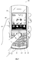
- FIG. 7 depicts a novel handheld communication device cradled in a user's hand and displaying an array of icons on a screen thereof, wherein a “Address Book” icon is shown as being highlighted;
- FIG. 8 depicts a novel handheld communication device cradled in a user's hand and displaying an array of icons on a screen thereof, wherein an “Media” icon is shown as being highlighted;
- FIG. 9 depicts a novel handheld communication device cradled in a user's hand and displaying an array of icons on a screen thereof, wherein a “Memo Pad” icon is shown as being highlighted;
- FIG. 10 depicts a novel handheld communication device cradled in a user's hand and displaying an array of icons on a screen thereof, wherein a “Search” icon is shown as being highlighted;
- FIG. 11 depicts a novel handheld communication device cradled in a user's hand and displaying an array of icons on a screen thereof, wherein a “Set Up Bluetooth” icon is shown as being highlighted;
- FIG. 12 a depicts a novel handheld communication device cradled in a user's hand and displaying an array of icons on a screen thereof, wherein a “Messages” icon is shown as being highlighted;
- FIG. 12 b depicts a novel handheld communication device cradled in a user's hand and displaying an array of icons on a screen thereof, wherein a “Calendar” icon is shown as being highlighted;
- FIG. 12 c depicts a novel handheld communication device cradled in a user's hand and displaying an array of icons on a screen thereof, wherein a “Messages” icon is shown as being highlighted;
- FIG. 12 d depicts a novel handheld communication device cradled in a user's hand and displaying an array of icons on a screen thereof, wherein a “Set up Bluetooth” icon is shown as being highlighted;
- FIG. 13 is an exploded perspective view of an exemplary wireless handheld electronic device incorporating a trackball assembly as at the auxiliary user input;
- FIG. 14 illustrates an exemplary QWERTY keyboard layout
- FIG. 15 illustrates an exemplary QWERTZ keyboard layout
- FIG. 16 illustrates an exemplary AZERTY keyboard layout
- FIG. 17 illustrates an exemplary Dvorak keyboard layout
- FIG. 18 illustrates a QWERTY keyboard layout paired with a traditional ten-key keyboard
- FIG. 19 illustrates ten digits comprising the numerals 0-9 arranged in a telephone keypad configuration, including the * and # flanking the zero;
- FIG. 20 illustrates a numeric phone key arrangement according to the ITU Standard E.161 including both numerals and letters;
- FIG. 21 is a front view of an exemplary handheld electronic device including a full QWERTY keyboard
- FIG. 22 is a front view of another exemplary handheld electronic device including a full QWERTY keyboard
- FIG. 23 is a front view of a handheld electronic device including a reduced QWERTY keyboard
- FIG. 24 is a closeup of a reduced QWERTY keyboard
- FIG. 25 is a detail view of an alternative reduced QWERTY keyboard
- FIG. 26 is a block diagram representing a wireless handheld communication device interacting in a communication network.
- the handheld electronic device to which this disclosure is directed is its size. While some users will grasp the device in both hands, it is intended that a predominance of users will cradle the device in one hand in such a manner that input and control over the device can be affected using the thumb of the same hand in which the device is held, however additional control can be effected by using both hands.
- the size of the device must be kept relatively small. Of the device's dimensions, limiting its width is important for the purpose of assuring cradleability in a user's hand.
- the width of the device be maintained at less than ten centimeters (approximately four inches). Keeping the device within these dimensional limits provides a hand cradleable unit that users prefer for its useability and portability. Limitations with respect to the height (length) of the device are less stringent when considering hand-cradleability. Therefore, in order to gain greater size, the device can be advantageously configured so that its height is greater than its width, but still remain easily supported and operated in one hand.
- a potential problem is presented by the small size of the device in that there is limited exterior surface area for the inclusion of user input and device output features. This is especially true for the “prime real estate” on the front face of the device, where it is most advantageous to include a display screen that outputs information to the user.
- the display screen is preferably located above a keyboard that is utilized for data entry into the device by the user. If the screen is provided below the keyboard, a problem occurs in that viewing the screen is inhibited when the user is inputting data using the keyboard. Therefore it is preferred that the display screen be above the input area, thereby solving the problem by assuring that the hands and fingers do not block the view of the screen during data entry periods.
- an alphabetic keyboard is provided.
- a full alphabetic keyboard is utilized in which there is one key per letter (see FIG. 22 for an example).
- This is preferred by some users because it can be arranged to resemble a standard keyboard with which they are most familiar.
- the associated letters can be advantageously organized in QWERTY, QWERTZ, AZERTY or Dvorak layouts, among others, thereby capitalizing on certain users' familiarity with these special letter orders.
- each of the keys In order to stay within the bounds of a limited front surface area, however, each of the keys must be commensurately small when, for example, twenty-six keys must be provided in the instance of the English language.
- An alternative configuration is to provide a reduced keyboard in which at least some of the keys have more than one letter associated therewith (see FIG. 23 for an example). This means that fewer keys are required which makes it possible for those fewer keys to each be larger than in the instance when a full keyboard is provided on a similarly dimensioned device. Some users will prefer the solution of the larger keys over the smaller ones, but it is necessary that software or hardware solutions be provided in order to discriminate which of the several associated letters the user intends based on a particular key actuation, a problem the full keyboard avoids. Preferably, this character discrimination is accomplished utilizing disambiguation software included on the device.
- a memory and microprocessor are provided within the body of the handheld unit for receiving, storing, processing, and outputting data during use. Therefore, the problem of needing a textual data input means is solved by the provision of either a full or reduced alphabetic keyboard on the presently disclosed handheld electronic device. It should be further appreciated that the keyboard can be alternatively provided on a touch sensitive screen in either a reduced or full format.
- the present handheld electronic device preferably includes an auxiliary input that acts as a cursor navigational tool and which is also exteriorly located upon the front face of the device. Its front face location is particularly advantageous because it makes the tool easily thumb-actuable like the keys of the keyboard.
- the navigational tool is a trackball which is easily utilized to instruct two-dimensional screen cursor movement in substantially any direction, as well as act as an actuator when the ball of the trackball is depressed like a button.
- the placement of the trackball is preferably above the keyboard and below the display screen; here, it avoids interference during keyboarding and does not block the user's view of the display screen during use (see FIG. 1 for an example).
- the handheld electronic device may be standalone in that it does not connect to the “outside world.”
- One example would be a PDA that stores such things as calendars and contact information but is not capable of synchronizing or communicating with other devices. In most situations such isolation will be viewed detrimentally in that synchronization is a highly desired characteristic of handheld devices today.
- the utility of the device is significantly enhanced when connectable within a system, and particularly when connectable on a wireless basis in a network in which voice, text messaging, and other data transfer are accommodated.
- known handheld electronic device 400 is shown as broadly comprising a thumbwheel 402 for affecting movement of highlighting cursor 404 amongst a plurality of icons 408 displayed on screen 406 of the device. More specifically, movement from one icon to another occurs serially and/or sequentially to the next icon along a row of icons and is affected by rotating the thumbwheel in one of an upward or downward direction. More specifically, as shown in FIG.
- the thumbwheel in order to move highlighting cursor 404 from a first row 410 of icons to a second row of icons 412 , the thumbwheel can be rotated in a downward direction, as shown by the arrow, such that the highlighted cursor is moved across the screen, from the left to the right side of the screen, along the first row of icons.
- rightward terminal icon 414 also labeled Memo Pad in FIG. 3
- continued downward rotation of the thumbwheel causes the highlighting cursor to “wrap” to leftward terminal icon 416 , also labeled Tasks in FIG. 3 , of a second row of icons immediately below the first row of icons.
- Similar opposite movement of the highlighting cursor can be accomplished by rotating the thumbwheel in an upward direction (not shown) so as to cause the highlighting cursor to move across the screen from right to left and upwards from one row to the next.
- a home position which can be the email icon 418 disposed in the upper left corner amongst the array of icons displayed, it can take significant time and effort to scroll through successive icons and/or rows to arrive at a desired icon that is to be selected.
- some devices allow users to navigate between rows without having to pass each successive icon in a row before navigating to a neighboring row, such devices require users to simultaneously depress “shift” or “alternate” keys, which ultimately requires the use of two hands.
- the handheld device 300 is cradleable in the palm of a user's hand.
- the handheld device is provided with a keyboard 332 to enter text data and place telephone calls and a display screen 322 for communicating information to the user.
- a connect/send key 609 is preferably provided to aid in the placement of a phone call.
- a disconnect/end key 605 is provided.
- the send key 609 and end key 605 preferably are arranged in a row of keys including a navigation tool 328 . Additionally, the row of keys including the navigation tool 328 preferably has a menu key 606 and an escape key 608 .
- the menu key 606 is used to bring up a menu and the escape key 608 is used to return to the previous screen or previous menu selection.
- the device 300 is of unibody construction, but it is also contemplated that the device may be of an alternative construction such as that commonly known as “clamshell” or “flip-phone” style.
- auxiliary user input 328 is located essentially between the display screen 322 and the keyboard 332 .
- the auxiliary user input is a trackball 121 . Motion of the trackball 121 can be assessed using a plurality of sensors that quantify rotational motion of the trackball 121 about axes intersecting with the trackball.
- Trackball 121 can also be configured to be depressable for purposes of selecting a function that is highlighted with a highlighting cursor.
- auxiliary user input devices can be used in the place of the trackball, e.g., touchpads, joysticks and the like and that, as shown in FIGS. 12 a - c , handheld device 300 can further comprise additional auxiliary inputs 350 , 351 for purposes of navigating highlighting cursor about the screen and/or for selecting highlighted functions.
- trackball 121 is provided for navigating highlighting cursor 352 amongst the icons of the screen display 322 .
- rotation of the trackball 121 toward the right side of the device in the direction of the arrow causes the highlighting cursor 352 to move from icon 354 , labeled “Messages”, to icon 356 , labeled “Call Log”.
- FIG. 6 continued rotation of the trackball in such direction causes the highlighting cursor to sequentially pass through the icons of that row until it reaches a terminal icon thereof, which, as shown in FIG.
- icon 358 labeled “Calendar.” Because the trackball 121 has been “pinned” to the sides of the display screen, continued rotation of the trackball toward the right side of the device does not result in the highlighting cursor 352 passing to a successive neighboring row of icons immediately below, as would normally occur in a device such as that of FIGS. 2 and 3 .
- the trackball can be rotated in an upward or downward direction toward the top and bottom of the device, i.e., toward the display screen and keyboard, respectively.
- the trackball 121 when the trackball 121 is rotated in a downward direction from icon 354 , “Messages”, the highlighting cursor successively passes along the leftward column to icon 360 , labeled “Address book,” to icon 362 , labeled “Media,” to icon 364 , labeled “MemoPad,” to icon 366 , labeled “Search,” and finally, to the columns' lower terminal icon 368 , labeled “Set up Bluetooth.” Further assertion of a downward directed force does not result in the highlighting cursor passing to the top of a neighboring column.
- commonly utilized icons such as “Messages,” Calendar,” “Set up Bluetooth,” and “Lock/Unlock,” can be arranged in the corners of the display screen amongst the plurality of icons.
- a user can simply navigate to such commonly used icons, often without the need to look at the device, by simply rotating the trackball in a requisite direction to arrive at such icons, which direction will typically be diagonal.
- the icons most commonly used and their disposition about the display screen either be pre-defined by the manufacturer or defined by the user.
- sensors can be used to ascertain whether navigation toward a commonly used icon is desired; such sensors can be configured for measuring increased trackball parameters, such as rotational force applied upon the trackball 121 or acceleration thereof, which increased trackball parameters are represented by the bold arrows of FIGS. 12 b and 12 d.
- device 300 can be configured such that the highlighting cursor can “skip” intermediately disposed icons and navigate substantially directly to icons disposed at the ends of the rows and columns.
- the highlighting cursor can be navigated substantially directly from icon 354 , labeled “Messages,” to icon 358 labeled “Calendar” by quickly rotating the trackball 121 in a rightward direction, or by depressing additional auxiliary user input 350 , which can comprise a button disposed on the right side of the handheld device.
- additional auxiliary user input 350 can comprise a button disposed on the right side of the handheld device.
- the highlighting cursor can be navigated directly from icon 354 , labeled “Messages,” to icon 368 , labeled “Set Up Bluetooth” by quickly rotating the trackball in a downward direction, or by depressing additional auxiliary user input 370 , which can comprise a button disposed near the bottom of the keyboard, or the “B” button to represent the term “bottom.”
- additional auxiliary user input 370 can comprise a button disposed near the bottom of the keyboard, or the “B” button to represent the term “bottom.”
- navigation to leftward or upward terminal icons can be accomplished by quickly rotating the trackball in the requisite direction or by depressing an additional auxiliary input 351 disposed on the left side of the device 300 in the case of navigating leftward or a button located near the top of the keyboard, or the “T” button 372 representing “top,” to navigate to an upwardly disposed terminal icon.
- An exemplary embodiment of the handheld electronic device 300 as shown in FIG. 1 is cradleable in the palm of a user's hand.
- the size of the device is such that a user is capable of operating the device 300 using the same hand that is holding the device 300 .
- the user is capable of actuating all features of the device 300 using the thumb of the cradling hand; however, in other embodiments features may require the use of more than just the thumb of the cradling hand.
- the preferred embodiment of the handheld device 300 features a keyboard on the face of the device 300 , which is actuable by the thumb of the hand cradling the device 300 .
- the user may also hold the device 300 in such a manner to enable two thumb typing on the device 300 .
- the handheld electronic device 300 includes an input portion and an output display portion.
- the output display portion can be a display screen 322 , such as an LCD or other similar display device.
- the input portion includes a plurality of keys that can be of a physical nature such as actuable buttons or they can be of a software nature, typically constituted by virtual representations of physical keys on a display screen (referred to herein as “software keys”). It is also contemplated that the user input can be provided as a combination of the two types of keys.
- Each key of the plurality of keys has at least one actuable action which can be the input of a character, a command or a function.
- “characters” are contemplated to exemplarily include alphabetic letters, language symbols, numbers, punctuation, insignias, icons, pictures, and even a blank space.
- Input commands and functions can include such things as delete, backspace, moving a cursor up, down, left or right, initiating an arithmetic function or command, initiating a command or function specific to an application program or feature in use, initiating a command or function programmed by the user and other such commands and functions that are well known to those persons skilled in the art.
- Specific keys or other types of input devices can be used to navigate through the various applications and features thereof. Further, depending on the application or feature in use, specific keys can be enabled or disabled.
- all or a portion of the plurality of keys have one or more indicia, representing character(s), command(s), and/or functions(s), displayed at their top surface and/or on the surface of the area adjacent the respective key.
- the indicia can be printed on the device cover beside the key, or in the instance of keys located adjacent the display screen 322 . Additionally, current indicia for the key may be temporarily shown nearby the key on the screen 322 .
- the indicia for the respective keys are shown on the display screen 322 , which in one embodiment is enabled by touching the display screen 322 , for example, with a stylus to generate the character or activate the indicated command or function.
- display screens 322 capable of detecting a touch include resistive, capacitive, projected capacitive, infrared and surface acoustic wave (SAW) touchscreens.
- Physical and software keys can be combined in many different ways as appreciated by those skilled in the art.
- physical and software keys are combined such that the plurality of enabled keys for a particular application or feature of the handheld electronic device 300 is shown on the display screen 322 in the same configuration as the physical keys. Using this configuration, the user can select the appropriate physical key corresponding to what is shown on the display screen 322 .
- the desired character, command or function is obtained by depressing the physical key corresponding to the character, command or function displayed at a corresponding position on the display screen 322 , rather than touching the display screen 322 .
- the various characters, commands and functions associated with keyboard typing in general are traditionally arranged using various conventions. The most common of these in the United States, for instance, is the QWERTY keyboard layout. Others include the QWERTZ, AZERTY, and Dvorak keyboard configurations.
- the QWERTY keyboard layout is the standard English-language alphabetic key arrangement 44 a shown in FIG. 14 .
- the QWERTZ keyboard layout is normally used in German-speaking regions; this alphabetic key arrangement 44 b is shown in FIG. 15 .
- the AZERTY keyboard layout 44 c is normally used in French-speaking regions and is shown in FIG. 16 .
- the Dvorak keyboard layout was designed to allow typists to type faster; this alphabetic key arrangement 44 d is shown in FIG. 17 .
- Alphabetic key arrangements are often presented along with numeric key arrangements.
- the numbers 1-9 and 0 are positioned in the row above the alphabetic keys 44 , as shown in FIGS. 14-17 .
- the numbers share keys with the alphabetic characters, such as the top row of the QWERTY keyboard (see FIG. 21 for an example).
- FIG. 18 Yet another exemplary numeric key arrangement is shown in FIG. 18 , where a “ten-key” style numeric keypad 46 is provided on a separate set of keys that is spaced from the alphabetic/numeric key arrangement 44 .
- the ten-key styled numeric keypad 46 includes the numbers “7”, “8”, “9” arranged in a top row, “4”, “5”, “6” arranged in a second row, “1”, “2”, “3” arranged in a third row, and “0” in a bottom row. Further, a numeric phone key arrangement 42 is exemplarily illustrated in FIG. 19 .
- the numeric phone key arrangement 42 may also utilize a surface treatment on the surface of the center “5” key.
- This surface treatment is configured such that the top surface of the key is distinctive from the surface of other keys.
- the surface treatment is in the form of a raised bump or recessed dimple 43 .
- raised bumps may be positioned on the housing around the “5” key and do not necessarily have to be positioned directly on the key.
- handheld electronic devices 300 it is desirable for handheld electronic devices 300 to include a combined text-entry keyboard and a telephony keyboard.
- mobile communication devices 300 include mobile stations, cellular telephones, wireless personal digital assistants (PDAs), two-way paging devices, and others.
- PDAs personal digital assistants
- Various keyboards are used with such devices and can be termed a full keyboard, a reduced keyboard, or phone key pad.
- the alphabetic characters are singly associated with the plurality of physical keys.
- FIGS. 21 and 22 Devices 300 incorporating full keyboards for the alphabetic characters are shown in FIGS. 21 and 22 . While both devices feature numeric keys, the device shown in FIG. 21 incorporates the numeric keys in a single row, whereas the device of FIG. 22 features numeric keys arranged according to the ITU Standard E.161 as shown in FIG. 19 . The latter numeric arrangement can be described as an overlaid numeric phone keypad arrangement.
- some handheld electronic devices 300 use a reduced keyboard, where more than one character/command/function is associated with each of at least a portion of the plurality of keys. This results in certain keys being ambiguous since more than one character is represented by or associated with the key, even though only one of those characters is typically intended by the user when activating the key.
- certain software usually runs on the processor of these types of handheld electronic device 300 to determine or predict what letter or word has been intended by the user.
- Some examples of software include predictive text routines which typically include a disambiguation engine and/or predictive editor application.
- the software preferably also has the ability to recognize character letter sequences that are common to the particular language, such as, in the case of English, words ending in “ming.” Such systems can also “learn” the typing style of the user making note of frequently used words to increase the predictive aspect of the software.
- Other types of predictive text computer programs may be utilized with the reduced keyboard arrangements described herein, without limitation. Some specific examples include the multi-tap method of character selection and “text on nine keys”.
- the keys of reduced keyboards are laid out with various arrangements of characters, commands and functions associated therewith.
- alphabetic characters the different keyboard layouts identified above are selectively used based on a user's preference and familiarity; for example, the QWERTY keyboard layout is most often used by English speakers who have become accustomed to the key arrangement.
- FIG. 1 shows a handheld electronic device 300 that carries an example of a reduced keyboard using the QWERTY keyboard layout on a physical keyboard array of twenty keys comprising five columns and four rows. Fourteen keys are used for alphabetic characters and ten keys are used for numbers. Nine of the ten numbers share a key with alphabetic characters. The “space” key and the number “0” share the same key, which is centered on the device and centered below the remainder of the numbers on the keyboard 332 . While in other embodiments, the number “0” may be located on other keys.
- FIG. 24 shows an example physical keyboard array of 20 keys composed of five columns and four rows.
- Fourteen keys on the keyboard 332 are associated with alphabetic characters and ten keys are associated with numbers. Many of the keys have different sizes than the other keys, and the rows are non-linear.
- the keys in the middle column 64 are wider than keys in the outer columns 60 , 62 , 66 and 68 .
- the numeric phone keys 0-9 include a color scheme that is different from that of the remaining keys associated with the QWERTY key arrangement.
- a color scheme of the numeric phone keys has a two tone appearance, with the upper portion of the numeric keys being a first color and the lower portion of the numeric keys being a second color.
- the first color may be lighter than the second color, or darker than the second color.
- the send key 6 and end key 8 are located on keys with alphabetic indicia have a background color and/or color of the symbols that are different from the other keys of the keyboard 332 .
- FIG. 25 shows a similar format for the reduced QWERTY arrangement of alphabetic characters 44 as presented in FIG. 23 , but the numeric phone key arrangement 42 is positioned in the first 60 , second 62 , and third 64 columns instead of being centered on the keyboard 332 . Thus, no numerals are presented on keys in the fourth 66 and fifth 68 columns.
- the first row 50 of keys includes in order the following key combinations for the text entry and telephony mode: “QW/1”, “ER/2”, “TY/3”, “UI”, and “OP”.
- the second row 52 includes the following key combinations in order: “AS/4”, “DF/5”, “GH/6”, “JK/,”, and “L/.”
- the third row 54 includes the following key combinations in order: “ZX/7”, “CV/8”, “BN/9”, “M/sym” and “backspace/delete”.
- the fourth row 56 includes the following key combinations in order: “next/*”, “space/0”, “shift/#”, “alt” and “return/enter”.
- the keys in each of the rows are of uniform size and the rows and columns are straight.
- a reduced alphabetic keyboard is found on a standard phone keypad.
- Most handheld electronic devices having a phone key pad also typically include alphabetic key arrangements overlaying or coinciding with the numeric keys as shown in FIG. 20 .
- Such alphanumeric phone keypads are used in many, if not most, traditional handheld telephony mobile communication devices such as cellular handsets.
- ITU International Telecommunications Union
- ITU Standard E.161 entitled “Arrangement of Digits, Letters, and Symbols on Telephones and Other Devices That Can Be Used for Gaining Access to a Telephone Network.”
- This standard is also known as ANSI TI.703-1995/1999 and ISO/IEC 9995-8:1994.
- ANSI TI.703-1995/1999 and ISO/IEC 9995-8:1994 Regarding the numeric arrangement, it can be aptly described as a top-to-bottom ascending order three-by-three-over-zero pattern.
- FIG. 13 is an exploded view showing some of the typical components found in the assembly of the handheld electronic device.
- the construction of the device benefits from various manufacturing simplifications.
- the internal components are constructed on a single PCB (printed circuit board) 102 .
- the keyboard 332 is constructed from a single piece of material, and in a preferred embodiment is made from plastic.
- the keyboard 332 sits over dome switches (not shown) located on the PCB 102 in a preferred embodiment.
- One switch is provided for every key on the keyboard in the preferred embodiment, but in other embodiments more than one switch or less than one switch per key are possible configurations.
- the support frame 101 holds the keyboard 332 and navigation tool 328 in place above the PCB 102 .
- the support frame 101 also provides an attachment point for the display (not shown).
- a lens 103 covers the display to prevent damage. When assembled, the support frame 101 and the PCB 102 are fixably attached to each other and the display is positioned between the PCB 102 and support frame 101 .
- the navigation tool 328 is frictionally engaged with the support frame 101 , but in a preferred embodiment the navigation tool 328 is removable when the device is assembled. This allows for replacement of the navigation tool 328 if/when it becomes damaged or the user desires replacement with a different type of navigation tool 328 .
- the navigation tool 328 is a ball 121 based device.
- Other navigation tools 328 such as joysticks, four-way cursors, or touch pads are also considered to be within the scope of this disclosure.
- the navigation tool 328 has a ball 121
- the ball 121 itself can be removed without removal of the navigation tool 328 .
- the removal of the ball 121 is enabled through the use of an outer removable ring 123 and an inner removable ring 122 . These rings 122 , 123 ensure that the navigation tool 328 and the ball 121 are properly held in place against the support frame 101 .
- a serial port (preferably a Universal Serial Bus port) 330 and an earphone jack 140 are fixably attached to the PCB 102 and further held in place by right side element 105 .
- Buttons 130 - 133 are attached to switches (not shown), which are connected to the PCB 102 .
- Final assembly involves placing the top piece 107 and bottom piece 108 in contact with support frame 101 . Furthermore, the assembly interconnects right side element 105 and left side element 106 with the support frame 101 , PCB 102 , and lens 103 . These side elements 106 , 105 provide additional protection and strength to the support structure of the device 300 . In a preferred embodiment, backplate 104 is removably attached to the other elements of the device.
- FIG. 26 An exemplary handheld electronic device 300 and its cooperation in a wireless network 319 is exemplified in the block diagram of FIG. 26 .
- This figure is exemplary only, and those persons skilled in the art will appreciate the additional elements and modifications necessary to make the device 300 work in particular network environments.
- FIG. 26 representing the communication device 300 interacting in the communication network 319 shows the device's 300 inclusion of a microprocessor 338 which controls the operation of the device 300 .
- the communication subsystem 311 performs all communication transmission and reception with the wireless network 319 .
- the microprocessor 338 further connects with an auxiliary input/output (I/O) subsystem 328 , a serial port (preferably a Universal Serial Bus port) 330 , a display 322 , a keyboard 332 , a speaker 334 , a microphone 336 , random access memory (RAM) 326 , and flash memory 324 .
- I/O auxiliary input/output
- serial port preferably a Universal Serial Bus port
- Other communication subsystems 340 and other device subsystems 342 are generally indicated as connected to the microprocessor 338 as well.
- An example of a communication subsystem 340 is that of a short range communication subsystem such as BLUETOOTH® communication module or an infrared device and associated circuits and components. Additionally, the microprocessor 338 is able to perform operating system functions and preferably enables execution of software applications on the communication device 300 .
- auxiliary I/O subsystem 328 can take a variety of different subsystems including the above described navigation tool.
- the navigation tool is preferably a trackball based device, but it can be a thumbwheel, navigation pad, or joystick. These navigation tools are preferably located on the front surface of the device 300 but may be located on an exterior surface of the device 300 .
- Other auxiliary I/O devices can include external display devices and externally connected keyboards (not shown). While the above examples have been provided in relation to the auxiliary I/O subsystem, other subsystems capable of providing input or receiving output from the handheld electronic device 300 are considered within the scope of this disclosure. Additionally, other keys may be placed along the side of the device 300 to function as escape keys, volume control keys, scrolling keys, power switches, or user programmable keys, which may be programmed accordingly.
- the flash memory 324 is enabled to provide a storage location for the operating system, device programs, and data. While the operating system in a preferred embodiment is stored in flash memory 324 , the operating system in other embodiments is stored in read-only memory (ROM) or similar storage element (not shown). As those skilled in the art will appreciate, the operating system, device application or parts thereof may be loaded in RAM 326 or other volatile memory.
- ROM read-only memory
- the flash memory 324 contains programs/applications 358 for execution on the device 300 including an address book 352 , a personal information manager (PIM) 354 , and the device state 350 . Furthermore, programs 358 and other information 356 including data can be segregated upon storage in the flash memory 324 of the device 300 .
- PIM personal information manager
- the device 300 When the device 300 is enabled for two-way communication within the wireless communication network 319 , it can send and receive signals from a mobile communication service.
- Examples of communication systems enabled for two-way communication include, but are not limited to, the GPRS (General Packet Radio Service) network, the UMTS (Universal Mobile Telecommunication Service) network, the EDGE (Enhanced Data for Global Evolution) network, and the CDMA (Code Division Multiple Access) network and those networks generally described as packet-switched, narrowband, data-only technologies mainly used for short burst wireless data transfer.
- the communication device 300 must be properly enabled to transmit and receive signals from the communication network 319 . Other systems may not require such identifying information.
- GPRS, UMTS, and EDGE require the use of a SIM (Subscriber Identity Module) in order to allow communication with the communication network 319 .
- SIM Subscriber Identity Module
- RUIM Removable Identity Module
- the RUIM and SIM card can be used in multiple different communication devices 300 .
- the communication device 300 may be able to operate some features without a SIM/RUIM card, but it will not be able to communicate with the network 319 .
- a SIM/RUIM interface 344 located within the device allows for removal or insertion of a SIM/RUIM card (not shown).
- the SIM/RUIM card features memory and holds key configurations 351 , and other information 353 such as identification and subscriber related information. With a properly enabled communication device 300 , two-way communication between the communication device 300 and communication network 319 is possible.
- the two-way communication enabled device 300 is able to both transmit and receive information from the communication network 319 .
- the transfer of communication can be from the device 300 or to the device 300 .
- the device 300 in a preferred embodiment is equipped with an integral or internal antenna 318 for transmitting signals to the communication network 319 .
- the communication device 300 in the preferred embodiment is equipped with another antenna 316 for receiving communication from the communication network 319 .
- These antennae ( 316 , 318 ) in another preferred embodiment are combined into a single antenna (not shown).
- the antenna or antennae ( 316 , 318 ) in another embodiment are externally mounted on the device 300 .
- the communication device 300 When equipped for two-way communication, the communication device 300 features a communication subsystem 311 . As is well known in the art, this communication subsystem 311 is modified so that it can support the operational needs of the device 300 .
- the subsystem 311 includes a transmitter 314 and receiver 312 including the associated antenna or antennae ( 316 , 318 ) as described above, local oscillators (LOs) 313 , and a processing module 320 which in a preferred embodiment is a digital signal processor (DSP) 320 .
- DSP digital signal processor
- communication by the device 300 with the wireless network 319 can be any type of communication that both the wireless network 319 and device 300 are enabled to transmit, receive and process. In general, these can be classified as voice and data.
- Voice communication is communication in which signals for audible sounds are transmitted by the device 300 through the communication network 319 .
- Data is all other types of communication that the device 300 is capable of performing within the constraints of the wireless network 319 .
Abstract
Description
Claims (22)
Priority Applications (1)
| Application Number | Priority Date | Filing Date | Title |
|---|---|---|---|
| US11/618,109 US8635559B2 (en) | 2006-12-29 | 2006-12-29 | On-screen cursor navigation delimiting on a handheld communication device |
Applications Claiming Priority (1)
| Application Number | Priority Date | Filing Date | Title |
|---|---|---|---|
| US11/618,109 US8635559B2 (en) | 2006-12-29 | 2006-12-29 | On-screen cursor navigation delimiting on a handheld communication device |
Publications (2)
| Publication Number | Publication Date |
|---|---|
| US20080163129A1 US20080163129A1 (en) | 2008-07-03 |
| US8635559B2 true US8635559B2 (en) | 2014-01-21 |
Family
ID=39585859
Family Applications (1)
| Application Number | Title | Priority Date | Filing Date |
|---|---|---|---|
| US11/618,109 Active 2030-05-18 US8635559B2 (en) | 2006-12-29 | 2006-12-29 | On-screen cursor navigation delimiting on a handheld communication device |
Country Status (1)
| Country | Link |
|---|---|
| US (1) | US8635559B2 (en) |
Cited By (1)
| Publication number | Priority date | Publication date | Assignee | Title |
|---|---|---|---|---|
| US9086782B2 (en) * | 2010-01-13 | 2015-07-21 | Fuji Xerox Co., Ltd. | Display-controlling device, display device, display-controlling method, and computer readable medium |
Families Citing this family (7)
| Publication number | Priority date | Publication date | Assignee | Title |
|---|---|---|---|---|
| JP2008243128A (en) * | 2007-03-29 | 2008-10-09 | Sanyo Electric Co Ltd | Touch panel device |
| KR20090017033A (en) * | 2007-08-13 | 2009-02-18 | 삼성전자주식회사 | Method for handling a portable device based on gui and apparatus thereof |
| KR101720578B1 (en) * | 2010-10-07 | 2017-03-29 | 삼성전자 주식회사 | Display apparatus and control method thereof |
| JP5641001B2 (en) * | 2012-02-20 | 2014-12-17 | 株式会社デンソー | Display control apparatus and display system |
| CN103677791B (en) * | 2012-09-26 | 2017-11-07 | 联想(北京)有限公司 | A kind of icon processing method and electronic equipment |
| CN103324478B (en) * | 2013-06-04 | 2016-12-28 | 惠州Tcl移动通信有限公司 | The application management method of mobile terminal and mobile terminal |
| JP6232804B2 (en) * | 2013-07-25 | 2017-11-22 | 株式会社デンソー | Vehicle user interface system |
Citations (8)
| Publication number | Priority date | Publication date | Assignee | Title |
|---|---|---|---|---|
| US20040001105A1 (en) * | 2002-06-28 | 2004-01-01 | Chew Chee H. | Method and system for presenting menu commands for selection |
| US6741232B1 (en) * | 2002-01-23 | 2004-05-25 | Good Technology, Inc. | User interface for a data processing apparatus |
| US20040155909A1 (en) * | 2003-02-07 | 2004-08-12 | Sun Microsystems, Inc. | Scroll tray mechanism for cellular telephone |
| US20040229663A1 (en) * | 2003-05-16 | 2004-11-18 | Tosey Joseph P. R. | Mobile electronic device with tactile keyboard |
| US6822664B2 (en) | 2000-10-11 | 2004-11-23 | Microsoft Corporation | Browser navigation for devices with a limited input system |
| US20060253801A1 (en) | 2005-09-23 | 2006-11-09 | Disney Enterprises, Inc. | Graphical user interface for electronic devices |
| US20080007571A1 (en) * | 2006-07-10 | 2008-01-10 | Chunkwok Lee | Trackball system and method for a mobile data processing device |
| US20080007528A1 (en) * | 2006-07-10 | 2008-01-10 | Chunkwok Lee | Trackball system and method for a mobile data processing device |
Family Cites Families (1)
| Publication number | Priority date | Publication date | Assignee | Title |
|---|---|---|---|---|
| WO2005112637A1 (en) * | 2004-05-14 | 2005-12-01 | Decode Chemistry, Inc. | Formulations for non-parenteral use including hydrophobic cyclodextrins |
-
2006
- 2006-12-29 US US11/618,109 patent/US8635559B2/en active Active
Patent Citations (8)
| Publication number | Priority date | Publication date | Assignee | Title |
|---|---|---|---|---|
| US6822664B2 (en) | 2000-10-11 | 2004-11-23 | Microsoft Corporation | Browser navigation for devices with a limited input system |
| US6741232B1 (en) * | 2002-01-23 | 2004-05-25 | Good Technology, Inc. | User interface for a data processing apparatus |
| US20040001105A1 (en) * | 2002-06-28 | 2004-01-01 | Chew Chee H. | Method and system for presenting menu commands for selection |
| US20040155909A1 (en) * | 2003-02-07 | 2004-08-12 | Sun Microsystems, Inc. | Scroll tray mechanism for cellular telephone |
| US20040229663A1 (en) * | 2003-05-16 | 2004-11-18 | Tosey Joseph P. R. | Mobile electronic device with tactile keyboard |
| US20060253801A1 (en) | 2005-09-23 | 2006-11-09 | Disney Enterprises, Inc. | Graphical user interface for electronic devices |
| US20080007571A1 (en) * | 2006-07-10 | 2008-01-10 | Chunkwok Lee | Trackball system and method for a mobile data processing device |
| US20080007528A1 (en) * | 2006-07-10 | 2008-01-10 | Chunkwok Lee | Trackball system and method for a mobile data processing device |
Non-Patent Citations (3)
| Title |
|---|
| Canadian Office Action mailed Jun. 6, 2011. In corresponding application No. 2,572,665. |
| Canadian Office Action mailed Sep. 29, 2009. In corresponding application No. 2,572,665. |
| Notice of Allowance and Fee(s) Due mailed Oct. 31, 2012, in corresponding Canadian patent application No. 2,572,665. |
Cited By (1)
| Publication number | Priority date | Publication date | Assignee | Title |
|---|---|---|---|---|
| US9086782B2 (en) * | 2010-01-13 | 2015-07-21 | Fuji Xerox Co., Ltd. | Display-controlling device, display device, display-controlling method, and computer readable medium |
Also Published As
| Publication number | Publication date |
|---|---|
| US20080163129A1 (en) | 2008-07-03 |
Similar Documents
| Publication | Publication Date | Title |
|---|---|---|
| US11029827B2 (en) | Text selection using a touch sensitive screen of a handheld mobile communication device | |
| US8537117B2 (en) | Handheld wireless communication device that selectively generates a menu in response to received commands | |
| CA2640785C (en) | Electronic device and method of controlling the same | |
| US8234588B2 (en) | System and method for panning and zooming an image on a display of a handheld electronic device | |
| US9417702B2 (en) | Method and apparatus for launching activities | |
| US20080303796A1 (en) | Shape-changing display for a handheld electronic device | |
| US8000741B2 (en) | Handheld wireless communication device with chamfer keys | |
| EP2000884A1 (en) | Shape-changing disply for a handheld electronic device | |
| US8635559B2 (en) | On-screen cursor navigation delimiting on a handheld communication device | |
| US20080163132A1 (en) | Streamlined navigation of a handheld elecronic device | |
| US7973765B2 (en) | Handheld wireless communication device | |
| US20070254721A1 (en) | Handheld wireless communication device | |
| US7986301B2 (en) | Handheld wireless communication device | |
| US20070254705A1 (en) | Handheld wireless communication device | |
| US7970431B2 (en) | Removable trackball for a handheld wireless communication device | |
| US20070254688A1 (en) | Handheld wireless communication device | |
| US20070254690A1 (en) | Handheld wireless communication device | |
| US8780046B2 (en) | Device and method for application navigation enhancement on a handheld electronic device | |
| US20070254702A1 (en) | Handheld wireless communication device | |
| US20080158159A1 (en) | On-screen cursor navigation on a handheld communication device displaying a modifed webpage | |
| US20080163111A1 (en) | Streamlined entry of appointment record | |
| US20070254698A1 (en) | Handheld wireless communication device | |
| CA2572665C (en) | On-screen cursor navigation delimiting on a handheld communication device | |
| US20070254703A1 (en) | Handheld wireless communication device | |
| CA2572659C (en) | On-screen cursor navigation on a handheld communication device displaying a modified webpage |
Legal Events
| Date | Code | Title | Description |
|---|---|---|---|
| AS | Assignment |
Owner name: RESEARCH IN MOTION LIMITED, CANADA Free format text: ASSIGNMENT OF ASSIGNORS INTEREST;ASSIGNORS:LEE, MATTHEW RICHARD;BUTT, FAHD SOHAIL;TALUKDAR, TANEEM;REEL/FRAME:018694/0385 Effective date: 20061222 |
|
| AS | Assignment |
Owner name: BLACKBERRY LIMITED, ONTARIO Free format text: CHANGE OF NAME;ASSIGNOR:RESEARCH IN MOTION LIMITED;REEL/FRAME:031435/0246 Effective date: 20130709 |
|
| STCF | Information on status: patent grant |
Free format text: PATENTED CASE |
|
| FPAY | Fee payment |
Year of fee payment: 4 |
|
| MAFP | Maintenance fee payment |
Free format text: PAYMENT OF MAINTENANCE FEE, 8TH YEAR, LARGE ENTITY (ORIGINAL EVENT CODE: M1552); ENTITY STATUS OF PATENT OWNER: LARGE ENTITY Year of fee payment: 8 |
|
| AS | Assignment |
Owner name: MALIKIE INNOVATIONS LIMITED, IRELAND Free format text: ASSIGNMENT OF ASSIGNORS INTEREST;ASSIGNOR:BLACKBERRY LIMITED;REEL/FRAME:064104/0103 Effective date: 20230511 |
|
| AS | Assignment |
Owner name: MALIKIE INNOVATIONS LIMITED, IRELAND Free format text: NUNC PRO TUNC ASSIGNMENT;ASSIGNOR:BLACKBERRY LIMITED;REEL/FRAME:064269/0001 Effective date: 20230511 |