US8629613B2 - Aromatic amine derivative and organic electroluminescent device using same - Google Patents
Aromatic amine derivative and organic electroluminescent device using same Download PDFInfo
- Publication number
- US8629613B2 US8629613B2 US11/813,394 US81339405A US8629613B2 US 8629613 B2 US8629613 B2 US 8629613B2 US 81339405 A US81339405 A US 81339405A US 8629613 B2 US8629613 B2 US 8629613B2
- Authority
- US
- United States
- Prior art keywords
- substituted
- group
- carbon atoms
- layer
- represented
- Prior art date
- Legal status (The legal status is an assumption and is not a legal conclusion. Google has not performed a legal analysis and makes no representation as to the accuracy of the status listed.)
- Expired - Fee Related
Links
- RZTDESRVPFKCBH-UHFFFAOYSA-N CC1=CC=C(C2=CC=C(C)C=C2)C=C1 Chemical compound CC1=CC=C(C2=CC=C(C)C=C2)C=C1 RZTDESRVPFKCBH-UHFFFAOYSA-N 0.000 description 166
- BMVVBWUXZYYZQP-UHFFFAOYSA-N CC1=CC=C(C2=CC=CC(C3=CC=CC=C3)=C2)C=C1 Chemical compound CC1=CC=C(C2=CC=CC(C3=CC=CC=C3)=C2)C=C1 BMVVBWUXZYYZQP-UHFFFAOYSA-N 0.000 description 60
- QIMMUPPBPVKWKM-UHFFFAOYSA-N CC1=CC=C2C=CC=CC2=C1 Chemical compound CC1=CC=C2C=CC=CC2=C1 QIMMUPPBPVKWKM-UHFFFAOYSA-N 0.000 description 54
- QPUYECUOLPXSFR-UHFFFAOYSA-N CC1=CC=CC2=C1C=CC=C2 Chemical compound CC1=CC=CC2=C1C=CC=C2 QPUYECUOLPXSFR-UHFFFAOYSA-N 0.000 description 53
- URLKBWYHVLBVBO-UHFFFAOYSA-N CC1=CC=C(C)C=C1 Chemical compound CC1=CC=C(C)C=C1 URLKBWYHVLBVBO-UHFFFAOYSA-N 0.000 description 50
- YXFVVABEGXRONW-UHFFFAOYSA-N CC1=CC=CC=C1 Chemical compound CC1=CC=CC=C1 YXFVVABEGXRONW-UHFFFAOYSA-N 0.000 description 50
- ZZLCFHIKESPLTH-UHFFFAOYSA-N CC1=CC=C(C2=CC=CC=C2)C=C1 Chemical compound CC1=CC=C(C2=CC=CC=C2)C=C1 ZZLCFHIKESPLTH-UHFFFAOYSA-N 0.000 description 43
- SZUYYIDZHIISBJ-UHFFFAOYSA-N CC1=CC2=C(C=C1)C1=C(C=CC=C1)C21CCCCC1 Chemical compound CC1=CC2=C(C=C1)C1=C(C=CC=C1)C21CCCCC1 SZUYYIDZHIISBJ-UHFFFAOYSA-N 0.000 description 34
- DXSIFZLOUITCRR-UHFFFAOYSA-N CC1=CC2=C(C=C1)C1=C(C=CC=C1)C2(C)C Chemical compound CC1=CC2=C(C=C1)C1=C(C=CC=C1)C2(C)C DXSIFZLOUITCRR-UHFFFAOYSA-N 0.000 description 31
- XNYPQVNKEFUPST-UHFFFAOYSA-N CC1=CC=C(C2=CC=C(C3=CC=CC=C3)C=C2)C=C1 Chemical compound CC1=CC=C(C2=CC=C(C3=CC=CC=C3)C=C2)C=C1 XNYPQVNKEFUPST-UHFFFAOYSA-N 0.000 description 31
- 0 [1*]C1=C(C)C2=C(C([6*])=C([7*])C([8*])=C2[9*])C2=C([5*])C([4*])=C([3*])C([2*])=C12 Chemical compound [1*]C1=C(C)C2=C(C([6*])=C([7*])C([8*])=C2[9*])C2=C([5*])C([4*])=C([3*])C([2*])=C12 0.000 description 31
- QGQWZCMAOAOOAH-UHFFFAOYSA-N CC1=CC2=C(C=C1)C1=C(C=C(C)C=C1)C21CCCCC1 Chemical compound CC1=CC2=C(C=C1)C1=C(C=C(C)C=C1)C21CCCCC1 QGQWZCMAOAOOAH-UHFFFAOYSA-N 0.000 description 21
- VFHCPNLOWVCHGV-UHFFFAOYSA-N CC1=CC2=C(C=C1)C1=C(C=C(C)C=C1)C2(C)C Chemical compound CC1=CC2=C(C=C1)C1=C(C=C(C)C=C1)C2(C)C VFHCPNLOWVCHGV-UHFFFAOYSA-N 0.000 description 20
- NKIXYJULGMJDDU-UHFFFAOYSA-N CC1=CC=C(C2=CC=C(C3=CC=C(C)C=C3)C=C2)C=C1 Chemical compound CC1=CC=C(C2=CC=C(C3=CC=C(C)C=C3)C=C2)C=C1 NKIXYJULGMJDDU-UHFFFAOYSA-N 0.000 description 20
- DALBHIYZSZZWBS-UHFFFAOYSA-N CC1=CC2=C(C=CC=C2)C2=C1C=CC=C2 Chemical compound CC1=CC2=C(C=CC=C2)C2=C1C=CC=C2 DALBHIYZSZZWBS-UHFFFAOYSA-N 0.000 description 16
- FNJLLLMNTROXOC-UHFFFAOYSA-N CC1=CC(C2=CC=CC=C2)=CC(C2=CC=CC=C2)=C1 Chemical compound CC1=CC(C2=CC=CC=C2)=CC(C2=CC=CC=C2)=C1 FNJLLLMNTROXOC-UHFFFAOYSA-N 0.000 description 14
- IXAFAYIIDHDJHN-UHFFFAOYSA-N CC1=CC2=C3C(=CC=C2)/C=C\C2=C\C=C/C1=C32 Chemical compound CC1=CC2=C3C(=CC=C2)/C=C\C2=C\C=C/C1=C32 IXAFAYIIDHDJHN-UHFFFAOYSA-N 0.000 description 14
- WZQDMECRFZDUBD-UHFFFAOYSA-N CC1=CC=C(C2=C3C=CC=CC3=C3C=CC=CC3=C2)C=C1 Chemical compound CC1=CC=C(C2=C3C=CC=CC3=C3C=CC=CC3=C2)C=C1 WZQDMECRFZDUBD-UHFFFAOYSA-N 0.000 description 14
- JTZVTVSSLYYVAM-UHFFFAOYSA-N CC1=CC=C(C2=CC=CC3=C2C=CC=C3)C=C1 Chemical compound CC1=CC=C(C2=CC=CC3=C2C=CC=C3)C=C1 JTZVTVSSLYYVAM-UHFFFAOYSA-N 0.000 description 14
- LDSUZJOZRKYGNI-UHFFFAOYSA-N CC1=CC=C(C2=CC=CC=C2)C2=C1C=CC=C2 Chemical compound CC1=CC=C(C2=CC=CC=C2)C2=C1C=CC=C2 LDSUZJOZRKYGNI-UHFFFAOYSA-N 0.000 description 14
- HQLHAPRTMMIZSV-UHFFFAOYSA-N CC1=CC=C2/C=C(C3=CC=CC=C3)\C=C/C2=C1 Chemical compound CC1=CC=C2/C=C(C3=CC=CC=C3)\C=C/C2=C1 HQLHAPRTMMIZSV-UHFFFAOYSA-N 0.000 description 14
- UBBMSATYENNTNA-UHFFFAOYSA-N CC1=CC=C(C2=CC3=C(C=C2)C2=C(C=CC=C2)C3(C)C)C=C1 Chemical compound CC1=CC=C(C2=CC3=C(C=C2)C2=C(C=CC=C2)C3(C)C)C=C1 UBBMSATYENNTNA-UHFFFAOYSA-N 0.000 description 13
- ZXXGUXICWKNYJD-UHFFFAOYSA-N CC1=CC=C(C2=CC=C3C=CC=CC3=C2)C=C1 Chemical compound CC1=CC=C(C2=CC=C3C=CC=CC3=C2)C=C1 ZXXGUXICWKNYJD-UHFFFAOYSA-N 0.000 description 13
- AYVWUPXIMBDBSX-UHFFFAOYSA-N CC1=CC=C(C2=CC=CC=C2)C(C2=CC=CC=C2)=C1 Chemical compound CC1=CC=C(C2=CC=CC=C2)C(C2=CC=CC=C2)=C1 AYVWUPXIMBDBSX-UHFFFAOYSA-N 0.000 description 13
- XHJKUHDKEFRGSK-UHFFFAOYSA-N CC1=CC=C2C3=C(C=CC=C3)/C3=C/C=C\C1=C23 Chemical compound CC1=CC=C2C3=C(C=CC=C3)/C3=C/C=C\C1=C23 XHJKUHDKEFRGSK-UHFFFAOYSA-N 0.000 description 13
- NWHMHERWVWRXLE-UHFFFAOYSA-N CN([Ar])[Ar].[Ar] Chemical compound CN([Ar])[Ar].[Ar] NWHMHERWVWRXLE-UHFFFAOYSA-N 0.000 description 3
- YJRUMGSTZOGWAL-UHFFFAOYSA-N CN([Ar])[Ar].[Ar].[Ar] Chemical compound CN([Ar])[Ar].[Ar].[Ar] YJRUMGSTZOGWAL-UHFFFAOYSA-N 0.000 description 3
- KBLJNRAGGVUKLM-UHFFFAOYSA-N C1=CC2=C(C=C1)C=CC=C2.CC.CC Chemical compound C1=CC2=C(C=C1)C=CC=C2.CC.CC KBLJNRAGGVUKLM-UHFFFAOYSA-N 0.000 description 2
- SRUHMSUWFJVBMM-UHFFFAOYSA-N C1=CC=C(C2=CC=CC(C3=CC=CC=C3)=C2)C=C1.CC.CC.CC Chemical compound C1=CC=C(C2=CC=CC(C3=CC=CC=C3)=C2)C=C1.CC.CC.CC SRUHMSUWFJVBMM-UHFFFAOYSA-N 0.000 description 2
- KAKOUNRRKSHVJO-UHFFFAOYSA-N CC.CC1=CC=CC=C1 Chemical compound CC.CC1=CC=CC=C1 KAKOUNRRKSHVJO-UHFFFAOYSA-N 0.000 description 2
- JKUIICUYLUVBBA-UHFFFAOYSA-N CC1=CC=C([Ar])C=C1.[Ar].[Ar].[Ar] Chemical compound CC1=CC=C([Ar])C=C1.[Ar].[Ar].[Ar] JKUIICUYLUVBBA-UHFFFAOYSA-N 0.000 description 2
- SDBGYZUAZCSSNI-UHFFFAOYSA-N BrC1=C/C2=C(\C=C/1)C1=C(C=CC=C1)C21CCCC1 Chemical compound BrC1=C/C2=C(\C=C/1)C1=C(C=CC=C1)C21CCCC1 SDBGYZUAZCSSNI-UHFFFAOYSA-N 0.000 description 1
- JLBXMPBCAYRQSZ-UHFFFAOYSA-N BrC1=C/C2=C(\C=C/1)C1=C(C=CC=C1)C21CCCCC1 Chemical compound BrC1=C/C2=C(\C=C/1)C1=C(C=CC=C1)C21CCCCC1 JLBXMPBCAYRQSZ-UHFFFAOYSA-N 0.000 description 1
- YRPIGRRBBMFFBE-UHFFFAOYSA-N BrC1=CC=C(C2=C3C=CC=CC3=CC=C2)C=C1 Chemical compound BrC1=CC=C(C2=C3C=CC=CC3=CC=C2)C=C1 YRPIGRRBBMFFBE-UHFFFAOYSA-N 0.000 description 1
- SAODOTSIOILVSO-UHFFFAOYSA-N BrC1=CC=C(C2=CC3=C(C=CC=C3)C=C2)C=C1 Chemical compound BrC1=CC=C(C2=CC3=C(C=CC=C3)C=C2)C=C1 SAODOTSIOILVSO-UHFFFAOYSA-N 0.000 description 1
- XCGVNJBBWRPIPZ-UHFFFAOYSA-N BrC1=CC=C(C2=CC=C(C3=C4C=CC=CC4=CC=C3)C=C2)C=C1 Chemical compound BrC1=CC=C(C2=CC=C(C3=C4C=CC=CC4=CC=C3)C=C2)C=C1 XCGVNJBBWRPIPZ-UHFFFAOYSA-N 0.000 description 1
- VBQIVFTUXFKGKW-UHFFFAOYSA-N BrC1=CC=C(C2=CC=C(N(C3=CC=C(C4=CC=CC=C4)C=C3)C3=CC=C(C4=CC=CC=C4)C=C3)C=C2)C=C1 Chemical compound BrC1=CC=C(C2=CC=C(N(C3=CC=C(C4=CC=CC=C4)C=C3)C3=CC=C(C4=CC=CC=C4)C=C3)C=C2)C=C1 VBQIVFTUXFKGKW-UHFFFAOYSA-N 0.000 description 1
- XUTVUTNJPNJUIK-UHFFFAOYSA-N BrC1=CC=C(C2=CC=C(N(C3=CC=C4C=CC=CC4=C3)C3=CC4=C(C=CC=C4)C=C3)C=C2)C=C1 Chemical compound BrC1=CC=C(C2=CC=C(N(C3=CC=C4C=CC=CC4=C3)C3=CC4=C(C=CC=C4)C=C3)C=C2)C=C1 XUTVUTNJPNJUIK-UHFFFAOYSA-N 0.000 description 1
- QCEOSYBXVSOSET-UHFFFAOYSA-N C.C.CNC(C)COC Chemical compound C.C.CNC(C)COC QCEOSYBXVSOSET-UHFFFAOYSA-N 0.000 description 1
- CXGVAMUMYOHLEP-UHFFFAOYSA-N C1=CC(C2=CC=C(N3C4=C(C=CC=C4)C4=C3C=CC=C4)C=C2)=CC(C2=CC(C3=CC=C(N4C5=C(C=CC=C5)C5=C4C=CC=C5)C=C3)=CC=C2)=C1.C1=CC=C(C2=CC(C3=CC=C(C4=CC=C(N5C6=C(C=CC=C6)C6=C5C=CC=C6)C=C4)C=C3)=NC(C3=CC=CC=C3)=N2)C=C1.C1=CC=C(C2=CC(C3=CC=C(N4C5=C(C=CC=C5)C5=C4C=CC=C5)C=C3)=CC(C3=CC(C4=CC=C(N5C6=C(C=CC=C6)C6=C5C=CC=C6)C=C4)=CC(C4=CC=CC=C4)=C3)=C2)C=C1.C1=CC=C(C2=CC(C3=CC=CC(C4=CC=C(N5C6=C(C=CC=C6)C6=C5C=CC=C6)C=C4)=C3)=CC(C3=CC=C(N4C5=C(C=CC=C5)C5=C4C=CC=C5)C=C3)=C2)C=C1.C1=CC=C(N2C3=C(C=CC=C3)C3=C2C=CC=C3)C=C1.CC1=CC=C(N2C3=C(C=CC=C3)C3=C2C=CC=C3)C=C1 Chemical compound C1=CC(C2=CC=C(N3C4=C(C=CC=C4)C4=C3C=CC=C4)C=C2)=CC(C2=CC(C3=CC=C(N4C5=C(C=CC=C5)C5=C4C=CC=C5)C=C3)=CC=C2)=C1.C1=CC=C(C2=CC(C3=CC=C(C4=CC=C(N5C6=C(C=CC=C6)C6=C5C=CC=C6)C=C4)C=C3)=NC(C3=CC=CC=C3)=N2)C=C1.C1=CC=C(C2=CC(C3=CC=C(N4C5=C(C=CC=C5)C5=C4C=CC=C5)C=C3)=CC(C3=CC(C4=CC=C(N5C6=C(C=CC=C6)C6=C5C=CC=C6)C=C4)=CC(C4=CC=CC=C4)=C3)=C2)C=C1.C1=CC=C(C2=CC(C3=CC=CC(C4=CC=C(N5C6=C(C=CC=C6)C6=C5C=CC=C6)C=C4)=C3)=CC(C3=CC=C(N4C5=C(C=CC=C5)C5=C4C=CC=C5)C=C3)=C2)C=C1.C1=CC=C(N2C3=C(C=CC=C3)C3=C2C=CC=C3)C=C1.CC1=CC=C(N2C3=C(C=CC=C3)C3=C2C=CC=C3)C=C1 CXGVAMUMYOHLEP-UHFFFAOYSA-N 0.000 description 1
- JWFDHUAAUBLWPE-UHFFFAOYSA-K C1=CC2=C(C=C1)C=C(C1=CC=C(C3=C4C=CC=CC4=C(C4=CC5=C(C=CC=C5)C=C4)C4=C3C=CC=C4)C=C1)C=C2.C1=CC2=C3C(=C1)O[Al]14(OC5=CC=CC6=C5/N1=C\C=C/6)(O/C1=C/C=C\C5=C1N4=CC=C5)N3=CC=C2.C1=CC2=CC=C(N(C3=CC=C(C=CC4=CC=C(N(C5=CC=C6C=CC=CC6=C5)C5=CC6=C(C=CC=C6)C=C5)C=C4)C=C3)C3=CC4=C(C=CC=C4)C=C3)C=C2C=C1.C1=CC=C(N(C2=CC=CC=C2)C2=CC=C(N(C3=CC=CC=C3)C3=CCC(C4C=CC(N(C5=CC=CC=C5)C5=CC=C(N(C6=CC=CC=C6)C6=CC=CC=C6)C=C5)=CC4)C=C3)C=C2)C=C1 Chemical compound C1=CC2=C(C=C1)C=C(C1=CC=C(C3=C4C=CC=CC4=C(C4=CC5=C(C=CC=C5)C=C4)C4=C3C=CC=C4)C=C1)C=C2.C1=CC2=C3C(=C1)O[Al]14(OC5=CC=CC6=C5/N1=C\C=C/6)(O/C1=C/C=C\C5=C1N4=CC=C5)N3=CC=C2.C1=CC2=CC=C(N(C3=CC=C(C=CC4=CC=C(N(C5=CC=C6C=CC=CC6=C5)C5=CC6=C(C=CC=C6)C=C5)C=C4)C=C3)C3=CC4=C(C=CC=C4)C=C3)C=C2C=C1.C1=CC=C(N(C2=CC=CC=C2)C2=CC=C(N(C3=CC=CC=C3)C3=CCC(C4C=CC(N(C5=CC=CC=C5)C5=CC=C(N(C6=CC=CC=C6)C6=CC=CC=C6)C=C5)=CC4)C=C3)C=C2)C=C1 JWFDHUAAUBLWPE-UHFFFAOYSA-K 0.000 description 1
- RAFZMZSNPMRFMU-UHFFFAOYSA-N C1=CC2=CC=C(N(C3=CC=C(C4=CC=C(N(C5=CC=C6C=CC=CC6=C5)C5=CC6=C(C=CC=C6)C=C5)C=C4)C=C3)C3=CC=C(C4=C5C=CC=CC5=CC=C4)C=C3)C=C2C=C1 Chemical compound C1=CC2=CC=C(N(C3=CC=C(C4=CC=C(N(C5=CC=C6C=CC=CC6=C5)C5=CC6=C(C=CC=C6)C=C5)C=C4)C=C3)C3=CC=C(C4=C5C=CC=CC5=CC=C4)C=C3)C=C2C=C1 RAFZMZSNPMRFMU-UHFFFAOYSA-N 0.000 description 1
- SBMXAWJSNIAHFR-UHFFFAOYSA-N C1=CC2=CC=C(NC3=CC4=C(C=CC=C4)C=C3)C=C2C=C1 Chemical compound C1=CC2=CC=C(NC3=CC4=C(C=CC=C4)C=C3)C=C2C=C1 SBMXAWJSNIAHFR-UHFFFAOYSA-N 0.000 description 1
- OCPRMCLWLSCMMS-UHFFFAOYSA-N C1=CC2=CC=C(NC3=CC=C(C4=C5C=CC=CC5=CC=C4)C=C3)C=C2C=C1 Chemical compound C1=CC2=CC=C(NC3=CC=C(C4=C5C=CC=CC5=CC=C4)C=C3)C=C2C=C1 OCPRMCLWLSCMMS-UHFFFAOYSA-N 0.000 description 1
- AAMUWUZDCAZDJB-UHFFFAOYSA-N C1=CC=C(C2=CC=C(C3=CC=C(N(C4=CC=C(C5=CC=C(N(C6=CC=C7C=CC=CC7=C6)C6=CC7=C(C=CC=C7)C=C6)C=C5)C=C4)C4=CC=C5C=CC=CC5=C4)C=C3)C=C2)C=C1 Chemical compound C1=CC=C(C2=CC=C(C3=CC=C(N(C4=CC=C(C5=CC=C(N(C6=CC=C7C=CC=CC7=C6)C6=CC7=C(C=CC=C7)C=C6)C=C5)C=C4)C4=CC=C5C=CC=CC5=C4)C=C3)C=C2)C=C1 AAMUWUZDCAZDJB-UHFFFAOYSA-N 0.000 description 1
- CYFUDYQAMJIHDH-UHFFFAOYSA-N C1=CC=C(C2=CC=C(C3=CC=C(N(C4=CC=C(C5=CC=CC=C5)C=C4)C4=CC=C(C5=CC=C(N(C6=CC=C(C7=CC=CC=C7)C=C6)C6=CC=C(C7=CC=CC=C7)C=C6)C=C5)C=C4)C=C3)C=C2)C=C1 Chemical compound C1=CC=C(C2=CC=C(C3=CC=C(N(C4=CC=C(C5=CC=CC=C5)C=C4)C4=CC=C(C5=CC=C(N(C6=CC=C(C7=CC=CC=C7)C=C6)C6=CC=C(C7=CC=CC=C7)C=C6)C=C5)C=C4)C=C3)C=C2)C=C1 CYFUDYQAMJIHDH-UHFFFAOYSA-N 0.000 description 1
- ZUKAOIXMUVCEEA-UHFFFAOYSA-N C1=CC=C(C2=CC=C(C3=CC=C(NC4=CC=C5C=CC=CC5=C4)C=C3)C=C2)C=C1 Chemical compound C1=CC=C(C2=CC=C(C3=CC=C(NC4=CC=C5C=CC=CC5=C4)C=C3)C=C2)C=C1 ZUKAOIXMUVCEEA-UHFFFAOYSA-N 0.000 description 1
- LALKMJCCXUWZMB-UHFFFAOYSA-N C1=CC=C(C2=CC=C(C3=NN=C(C4=CC=C(C5=CC=C(C6=NN=C(C7=CC=C(C8=CC=CC=C8)C=C7)O6)C=C5)C=C4)O3)C=C2)C=C1.C1=CC=C(C2=CC=C(C3=NN=C(C4=CC=C(OC5=CC=C(C6=NN=C(C7=CC=C(C8=CC=CC=C8)C=C7)O6)C=C5)C=C4)O3)C=C2)C=C1.CC1=CC(C2=CC(C)=C(C3=NN=C(C4=C5C=CC=CC5=CC=C4)O3)C=C2)=CC=C1C1=NN=C(C2=CC=CC3=C2C=CC=C3)O1.CC1=CC=C(C2=CC=C(C3=NN=C(C4=CC=C(C5=CC=C(C6=NN=C(C7=CC=C(C8=CC=C(C)C=C8)C=C7)O6)C=C5)C=C4)O3)C=C2)C=C1.CC1=CC=C(C2=CC=C(C3=NN=C(C4=CC=CC=C4)O3)C=C2)C=C1 Chemical compound C1=CC=C(C2=CC=C(C3=NN=C(C4=CC=C(C5=CC=C(C6=NN=C(C7=CC=C(C8=CC=CC=C8)C=C7)O6)C=C5)C=C4)O3)C=C2)C=C1.C1=CC=C(C2=CC=C(C3=NN=C(C4=CC=C(OC5=CC=C(C6=NN=C(C7=CC=C(C8=CC=CC=C8)C=C7)O6)C=C5)C=C4)O3)C=C2)C=C1.CC1=CC(C2=CC(C)=C(C3=NN=C(C4=C5C=CC=CC5=CC=C4)O3)C=C2)=CC=C1C1=NN=C(C2=CC=CC3=C2C=CC=C3)O1.CC1=CC=C(C2=CC=C(C3=NN=C(C4=CC=C(C5=CC=C(C6=NN=C(C7=CC=C(C8=CC=C(C)C=C8)C=C7)O6)C=C5)C=C4)O3)C=C2)C=C1.CC1=CC=C(C2=CC=C(C3=NN=C(C4=CC=CC=C4)O3)C=C2)C=C1 LALKMJCCXUWZMB-UHFFFAOYSA-N 0.000 description 1
- RMXHMEFTZCCLCD-UHFFFAOYSA-N C1=CC=C(C2=CC=C(N(C3=CC=C(C4=CC=CC=C4)C=C3)C3=CC=C(C4=CC=C(C5=CC=C(N(C6=CC=C(C7=CC=CC=C7)C=C6)C6=CC=CC7=C6C=CC=C7)C=C5)C=C4)C=C3)C=C2)C=C1 Chemical compound C1=CC=C(C2=CC=C(N(C3=CC=C(C4=CC=CC=C4)C=C3)C3=CC=C(C4=CC=C(C5=CC=C(N(C6=CC=C(C7=CC=CC=C7)C=C6)C6=CC=CC7=C6C=CC=C7)C=C5)C=C4)C=C3)C=C2)C=C1 RMXHMEFTZCCLCD-UHFFFAOYSA-N 0.000 description 1
- LCLCWDNINJWSSY-UHFFFAOYSA-N C1=CC=C(C2=CC=C(N(C3=CC=C(C4=CC=CC=C4)C=C3)C3=CC=C(C4=CC=C(N(C5=CC=C(C6=CC=CC=C6)C=C5)C5=C/C6=C(\C=C/5)C5=C(C=CC=C5)C65CCCC5)C=C4)C=C3)C=C2)C=C1 Chemical compound C1=CC=C(C2=CC=C(N(C3=CC=C(C4=CC=CC=C4)C=C3)C3=CC=C(C4=CC=C(N(C5=CC=C(C6=CC=CC=C6)C=C5)C5=C/C6=C(\C=C/5)C5=C(C=CC=C5)C65CCCC5)C=C4)C=C3)C=C2)C=C1 LCLCWDNINJWSSY-UHFFFAOYSA-N 0.000 description 1
- QNEQSSWKTOPJTI-UHFFFAOYSA-N C1=CC=C(C2=CC=C(N(C3=CC=C(C4=CC=CC=C4)C=C3)C3=CC=C(C4=CC=C(N(C5=CC=C(C6=CC=CC=C6)C=C5)C5=C/C6=C(\C=C/5)C5=C(C=CC=C5)C65CCCCC5)C=C4)C=C3)C=C2)C=C1 Chemical compound C1=CC=C(C2=CC=C(N(C3=CC=C(C4=CC=CC=C4)C=C3)C3=CC=C(C4=CC=C(N(C5=CC=C(C6=CC=CC=C6)C=C5)C5=C/C6=C(\C=C/5)C5=C(C=CC=C5)C65CCCCC5)C=C4)C=C3)C=C2)C=C1 QNEQSSWKTOPJTI-UHFFFAOYSA-N 0.000 description 1
- GFBLXNSYUGSZJK-UHFFFAOYSA-N C1=CC=C(C2=CC=C(N(C3=CC=C(C4=CC=CC=C4)C=C3)C3=CC=C(C4=CC=C(N(C5=CC=C(C6=CC=CC=C6)C=C5)C5=CC(C6=CC=CC=C6)=CC(C6=CC=CC=C6)=C5)C=C4)C=C3)C=C2)C=C1 Chemical compound C1=CC=C(C2=CC=C(N(C3=CC=C(C4=CC=CC=C4)C=C3)C3=CC=C(C4=CC=C(N(C5=CC=C(C6=CC=CC=C6)C=C5)C5=CC(C6=CC=CC=C6)=CC(C6=CC=CC=C6)=C5)C=C4)C=C3)C=C2)C=C1 GFBLXNSYUGSZJK-UHFFFAOYSA-N 0.000 description 1
- DGQDOXAYDDKKOL-UHFFFAOYSA-N C1=CC=C(C2=CC=C(N(C3=CC=C(C4=CC=CC=C4)C=C3)C3=CC=C(C4=CC=C(N(C5=CC=C(C6=CC=CC=C6)C=C5)C5=CC6=C(/C=C\C=C/6)C6=C5C=CC=C6)C=C4)C=C3)C=C2)C=C1 Chemical compound C1=CC=C(C2=CC=C(N(C3=CC=C(C4=CC=CC=C4)C=C3)C3=CC=C(C4=CC=C(N(C5=CC=C(C6=CC=CC=C6)C=C5)C5=CC6=C(/C=C\C=C/6)C6=C5C=CC=C6)C=C4)C=C3)C=C2)C=C1 DGQDOXAYDDKKOL-UHFFFAOYSA-N 0.000 description 1
- JHNWYXJWBZOOOC-UHFFFAOYSA-N C1=CC=C(C2=CC=C(N(C3=CC=C(C4=CC=CC=C4)C=C3)C3=CC=C(C4=CC=C(N(C5=CC=C(C6=CC=CC=C6)C=C5)C5=CC=C(C6=C7C=CC=CC7=CC=C6)C=C5)C=C4)C=C3)C=C2)C=C1 Chemical compound C1=CC=C(C2=CC=C(N(C3=CC=C(C4=CC=CC=C4)C=C3)C3=CC=C(C4=CC=C(N(C5=CC=C(C6=CC=CC=C6)C=C5)C5=CC=C(C6=C7C=CC=CC7=CC=C6)C=C5)C=C4)C=C3)C=C2)C=C1 JHNWYXJWBZOOOC-UHFFFAOYSA-N 0.000 description 1
- HDNWFFGMUXRORR-UHFFFAOYSA-N C1=CC=C(C2=CC=C(N(C3=CC=C(C4=CC=CC=C4)C=C3)C3=CC=C(C4=CC=C(N(C5=CC=C(C6=CC=CC=C6)C=C5)C5=CC=C(C6=CC(C7=CC=CC=C7)=CC=C6)C=C5)C=C4)C=C3)C=C2)C=C1 Chemical compound C1=CC=C(C2=CC=C(N(C3=CC=C(C4=CC=CC=C4)C=C3)C3=CC=C(C4=CC=C(N(C5=CC=C(C6=CC=CC=C6)C=C5)C5=CC=C(C6=CC(C7=CC=CC=C7)=CC=C6)C=C5)C=C4)C=C3)C=C2)C=C1 HDNWFFGMUXRORR-UHFFFAOYSA-N 0.000 description 1
- KLSJWOVIOOGJCK-UHFFFAOYSA-N C1=CC=C(C2=CC=C(N(C3=CC=C(C4=CC=CC=C4)C=C3)C3=CC=C(C4=CC=C(N(C5=CC=C(C6=CC=CC=C6)C=C5)C5=CC=C(C6=CC7=C(C=CC=C7)C=C6)C=C5)C=C4)C=C3)C=C2)C=C1 Chemical compound C1=CC=C(C2=CC=C(N(C3=CC=C(C4=CC=CC=C4)C=C3)C3=CC=C(C4=CC=C(N(C5=CC=C(C6=CC=CC=C6)C=C5)C5=CC=C(C6=CC7=C(C=CC=C7)C=C6)C=C5)C=C4)C=C3)C=C2)C=C1 KLSJWOVIOOGJCK-UHFFFAOYSA-N 0.000 description 1
- IPAOPPFXYTWBSF-UHFFFAOYSA-N C1=CC=C(C2=CC=C(N(C3=CC=C(C4=CC=CC=C4)C=C3)C3=CC=C(C4=CC=C(N(C5=CC=C(C6=CC=CC=C6)C=C5)C5=CC=C(C6=CC=C(C7=C8C=CC=CC8=CC=C7)C=C6)C=C5)C=C4)C=C3)C=C2)C=C1 Chemical compound C1=CC=C(C2=CC=C(N(C3=CC=C(C4=CC=CC=C4)C=C3)C3=CC=C(C4=CC=C(N(C5=CC=C(C6=CC=CC=C6)C=C5)C5=CC=C(C6=CC=C(C7=C8C=CC=CC8=CC=C7)C=C6)C=C5)C=C4)C=C3)C=C2)C=C1 IPAOPPFXYTWBSF-UHFFFAOYSA-N 0.000 description 1
- OZGCPIZNUGYSPJ-UHFFFAOYSA-N C1=CC=C(C2=CC=C(N(C3=CC=C(C4=CC=CC=C4)C=C3)C3=CC=C(C4=CC=C(N(C5=CC=C(C6=CC=CC=C6)C=C5)C5=CC=CC6=C5C=CC=C6)C=C4)C=C3)C=C2)C=C1 Chemical compound C1=CC=C(C2=CC=C(N(C3=CC=C(C4=CC=CC=C4)C=C3)C3=CC=C(C4=CC=C(N(C5=CC=C(C6=CC=CC=C6)C=C5)C5=CC=CC6=C5C=CC=C6)C=C4)C=C3)C=C2)C=C1 OZGCPIZNUGYSPJ-UHFFFAOYSA-N 0.000 description 1
- DOTSEUKJBPAPGG-UHFFFAOYSA-N C1=CC=C(C2=CC=C(NC3=CC=C(C4=C5C=CC=CC5=CC=C4)C=C3)C=C2)C=C1 Chemical compound C1=CC=C(C2=CC=C(NC3=CC=C(C4=C5C=CC=CC5=CC=C4)C=C3)C=C2)C=C1 DOTSEUKJBPAPGG-UHFFFAOYSA-N 0.000 description 1
- SJXDKVIQCRMTOS-UHFFFAOYSA-N C1=CC=C(C2=CC=C(NC3=CC=C(C4=CC5=C(C=CC=C5)C=C4)C=C3)C=C2)C=C1 Chemical compound C1=CC=C(C2=CC=C(NC3=CC=C(C4=CC5=C(C=CC=C5)C=C4)C=C3)C=C2)C=C1 SJXDKVIQCRMTOS-UHFFFAOYSA-N 0.000 description 1
- LPUDPWGKNCPKTP-UHFFFAOYSA-N C1=CC=C(C2=CC=C(NC3=CC=C(C4=CC=C(C5=C6C=CC=CC6=CC=C5)C=C4)C=C3)C=C2)C=C1 Chemical compound C1=CC=C(C2=CC=C(NC3=CC=C(C4=CC=C(C5=C6C=CC=CC6=CC=C5)C=C4)C=C3)C=C2)C=C1 LPUDPWGKNCPKTP-UHFFFAOYSA-N 0.000 description 1
- MAOFYQZGOHNLTP-UHFFFAOYSA-N C1=CC=C(C2=CC=C(NC3=CC=C(C4=CC=C(C5=CC=CC=C5)C=C4)C=C3)C=C2)C=C1 Chemical compound C1=CC=C(C2=CC=C(NC3=CC=C(C4=CC=C(C5=CC=CC=C5)C=C4)C=C3)C=C2)C=C1 MAOFYQZGOHNLTP-UHFFFAOYSA-N 0.000 description 1
- JAUCIDPGGHZXRP-UHFFFAOYSA-N C1=CC=C(C2=CC=C(NC3=CC=C(C4=CC=CC=C4)C=C3)C=C2)C=C1 Chemical compound C1=CC=C(C2=CC=C(NC3=CC=C(C4=CC=CC=C4)C=C3)C=C2)C=C1 JAUCIDPGGHZXRP-UHFFFAOYSA-N 0.000 description 1
- KIYUIZKNSAKHLS-UHFFFAOYSA-N C1=CC=C(C2=NC(C3=CC=CC=C3)=NC(C3=CC(C4=CC=C(N5C6=C(C=CC=C6)C6=C5C=CC=C6)C=C4)=CC=C3)=C2)C=C1 Chemical compound C1=CC=C(C2=NC(C3=CC=CC=C3)=NC(C3=CC(C4=CC=C(N5C6=C(C=CC=C6)C6=C5C=CC=C6)C=C4)=CC=C3)=C2)C=C1 KIYUIZKNSAKHLS-UHFFFAOYSA-N 0.000 description 1
- NOPLCHDUDWJSSB-UHFFFAOYSA-N C1=CC=C(N(C2=CC=CC=C2)C2=CC=C(C3=CC=C(N(C4=CC=CC=C4)C4=CC=CC5=C4C=CC=C5)C=C3)C=C2)C=C1 Chemical compound C1=CC=C(N(C2=CC=CC=C2)C2=CC=C(C3=CC=C(N(C4=CC=CC=C4)C4=CC=CC5=C4C=CC=C5)C=C3)C=C2)C=C1 NOPLCHDUDWJSSB-UHFFFAOYSA-N 0.000 description 1
- ZWJKPLCRKXHQCU-UHFFFAOYSA-N CC.CC.CC.CC.[Ar]C1=C2C=CC=CC2=C(C2=CC=CC=C2)C2=CC=CC=C21 Chemical compound CC.CC.CC.CC.[Ar]C1=C2C=CC=CC2=C(C2=CC=CC=C2)C2=CC=CC=C21 ZWJKPLCRKXHQCU-UHFFFAOYSA-N 0.000 description 1
- WFXOHRWMOPZSQW-UHFFFAOYSA-N CC.CC.CN(C1=CC=CC=C1)C1=CC=CC=C1 Chemical compound CC.CC.CN(C1=CC=CC=C1)C1=CC=CC=C1 WFXOHRWMOPZSQW-UHFFFAOYSA-N 0.000 description 1
- INBBVPBWNAUORA-UHFFFAOYSA-N CC1(C)C2=C(C=CC=C2)C2=C1/C=C(N(C1=CC=C(C3=CC=CC=C3)C=C1)C1=CC=C(C3=CC=C(N(C4=CC=C(C5=CC=CC=C5)C=C4)C4=CC=C(C5=CC=CC=C5)C=C4)C=C3)C=C1)\C=C/2 Chemical compound CC1(C)C2=C(C=CC=C2)C2=C1/C=C(N(C1=CC=C(C3=CC=CC=C3)C=C1)C1=CC=C(C3=CC=C(N(C4=CC=C(C5=CC=CC=C5)C=C4)C4=CC=C(C5=CC=CC=C5)C=C4)C=C3)C=C1)\C=C/2 INBBVPBWNAUORA-UHFFFAOYSA-N 0.000 description 1
- PZPSURICQAGVDO-UHFFFAOYSA-N CC1=CC=C(N(C2=CC=C(C)C=C2)C2=C3C=CC=CC3=C3/C=C(/N(C4=CC=C(C)C=C4)C4=CC=C(C)C=C4)C4=C(C=CC=C4)C3=C2)C=C1 Chemical compound CC1=CC=C(N(C2=CC=C(C)C=C2)C2=C3C=CC=CC3=C3/C=C(/N(C4=CC=C(C)C=C4)C4=CC=C(C)C=C4)C4=C(C=CC=C4)C3=C2)C=C1 PZPSURICQAGVDO-UHFFFAOYSA-N 0.000 description 1
- YVSMRTOGMKSFCA-UHFFFAOYSA-N CC1=NN=C(C)O1.CC1=NN=C(CC2=NN=C(C)O2)O1.CC1=NN=C(COCC2=NN=C(C)O2)O1 Chemical compound CC1=NN=C(C)O1.CC1=NN=C(CC2=NN=C(C)O2)O1.CC1=NN=C(COCC2=NN=C(C)O2)O1 YVSMRTOGMKSFCA-UHFFFAOYSA-N 0.000 description 1
- PGTOHXREKFVJHG-UHFFFAOYSA-N CN(C1=CC=C([Ar])C=C1)C1=CC=C([Ar])C=C1.[Ar].[Ar].[Ar].[Ar].[Ar].[Ar].[Ar].[Ar].[Ar].[Ar].[Ar].[Ar] Chemical compound CN(C1=CC=C([Ar])C=C1)C1=CC=C([Ar])C=C1.[Ar].[Ar].[Ar].[Ar].[Ar].[Ar].[Ar].[Ar].[Ar].[Ar].[Ar].[Ar] PGTOHXREKFVJHG-UHFFFAOYSA-N 0.000 description 1
- FCAWLHOHCONATK-UHFFFAOYSA-N CN([Ar])[Ar].[Ar].[Ar].[Ar].[Ar].[Ar].[Ar].[Ar].[Ar].[Ar].[Ar].[Ar].[Ar].[Ar].[Ar].[Ar].[Ar].[Ar] Chemical compound CN([Ar])[Ar].[Ar].[Ar].[Ar].[Ar].[Ar].[Ar].[Ar].[Ar].[Ar].[Ar].[Ar].[Ar].[Ar].[Ar].[Ar].[Ar].[Ar] FCAWLHOHCONATK-UHFFFAOYSA-N 0.000 description 1
- MEFVRZUYMHQQEG-UHFFFAOYSA-N CN([Ar])[Ar].[Ar].[Ar].[Ar].[Ar].[Ar].[Ar].[Ar].[Ar].[Ar].[Ar].[Ar].[Ar].[Ar].[Ar].[Ar].[Ar].[Ar].[Ar].[Ar].[Ar].[Ar].[Ar].[Ar] Chemical compound CN([Ar])[Ar].[Ar].[Ar].[Ar].[Ar].[Ar].[Ar].[Ar].[Ar].[Ar].[Ar].[Ar].[Ar].[Ar].[Ar].[Ar].[Ar].[Ar].[Ar].[Ar].[Ar].[Ar].[Ar].[Ar] MEFVRZUYMHQQEG-UHFFFAOYSA-N 0.000 description 1
- POQBQCSUWKFMRT-KQQHOMHOSA-N C[C@@H](CC[C@@H](C)NC(C1N)c2ccc(C)c3c2c1ccc3)CN Chemical compound C[C@@H](CC[C@@H](C)NC(C1N)c2ccc(C)c3c2c1ccc3)CN POQBQCSUWKFMRT-KQQHOMHOSA-N 0.000 description 1
- FSAFVTWFFGVWRP-UHFFFAOYSA-N Cc1ccc2c(c1)C1(c3cc(C)ccc3-2)c2cc(C)ccc2-c2ccc(C)cc21 Chemical compound Cc1ccc2c(c1)C1(c3cc(C)ccc3-2)c2cc(C)ccc2-c2ccc(C)cc21 FSAFVTWFFGVWRP-UHFFFAOYSA-N 0.000 description 1
- KIDOMBXDDKLWJI-UHFFFAOYSA-N IC1=CC(C2=CC=CC=C2)=CC(C2=CC=CC=C2)=C1.IC1=CC=C(C2=CC(C3=CC=CC=C3)=CC=C2)C=C1 Chemical compound IC1=CC(C2=CC=CC=C2)=CC(C2=CC=CC=C2)=C1.IC1=CC=C(C2=CC(C3=CC=CC=C3)=CC=C2)C=C1 KIDOMBXDDKLWJI-UHFFFAOYSA-N 0.000 description 1
- VXTDSGFZSYYQNR-UHFFFAOYSA-N OB(O)C1=CC=C(N(C2=CC=C(C3=CC=CC=C3)C=C2)C2=C3C=CC=CC3=CC=C2)C=C1 Chemical compound OB(O)C1=CC=C(N(C2=CC=C(C3=CC=CC=C3)C=C2)C2=C3C=CC=CC3=CC=C2)C=C1 VXTDSGFZSYYQNR-UHFFFAOYSA-N 0.000 description 1
- XMUUGQPZYBWERT-UHFFFAOYSA-N [H]N(C(=O)C1=CC=CC=C1)C1=CC=C(C2=CC=CC=C2)C=C1 Chemical compound [H]N(C(=O)C1=CC=CC=C1)C1=CC=C(C2=CC=CC=C2)C=C1 XMUUGQPZYBWERT-UHFFFAOYSA-N 0.000 description 1
- QRMLAMCEPKEKHS-UHFFFAOYSA-N [H]N(C1=CC=C(C2=CC=CC=C2)C=C1)C1=C/C2=C(/C=C/1)C1=C(C=CC=C1)C2(C)C Chemical compound [H]N(C1=CC=C(C2=CC=CC=C2)C=C1)C1=C/C2=C(/C=C/1)C1=C(C=CC=C1)C2(C)C QRMLAMCEPKEKHS-UHFFFAOYSA-N 0.000 description 1
- ZMXIDKPXLYFVKZ-UHFFFAOYSA-N [H]N(C1=CC=C(C2=CC=CC=C2)C=C1)C1=C/C2=C(/C=C/1)C1=C(C=CC=C1)C21CCCC1 Chemical compound [H]N(C1=CC=C(C2=CC=CC=C2)C=C1)C1=C/C2=C(/C=C/1)C1=C(C=CC=C1)C21CCCC1 ZMXIDKPXLYFVKZ-UHFFFAOYSA-N 0.000 description 1
- JWZDLMYMZOSQQM-UHFFFAOYSA-N [H]N(C1=CC=C(C2=CC=CC=C2)C=C1)C1=C/C2=C(/C=C/1)C1=C(C=CC=C1)C21CCCCC1 Chemical compound [H]N(C1=CC=C(C2=CC=CC=C2)C=C1)C1=C/C2=C(/C=C/1)C1=C(C=CC=C1)C21CCCCC1 JWZDLMYMZOSQQM-UHFFFAOYSA-N 0.000 description 1
- KMZYGUOYACANFQ-UHFFFAOYSA-N [H]N(C1=CC=C(C2=CC=CC=C2)C=C1)C1=CC(C2=CC=CC=C2)=CC(C2=CC=CC=C2)=C1 Chemical compound [H]N(C1=CC=C(C2=CC=CC=C2)C=C1)C1=CC(C2=CC=CC=C2)=CC(C2=CC=CC=C2)=C1 KMZYGUOYACANFQ-UHFFFAOYSA-N 0.000 description 1
- WMOTUYHWZHRYRH-UHFFFAOYSA-N [H]N(C1=CC=C(C2=CC=CC=C2)C=C1)C1=CC2=C(C=CC=C2)C2=C1C=CC=C2 Chemical compound [H]N(C1=CC=C(C2=CC=CC=C2)C=C1)C1=CC2=C(C=CC=C2)C2=C1C=CC=C2 WMOTUYHWZHRYRH-UHFFFAOYSA-N 0.000 description 1
- VOUOTHIDSLJELI-UHFFFAOYSA-N [H]N(C1=CC=C(C2=CC=CC=C2)C=C1)C1=CC=C(C2=CC(C3=CC=CC=C3)=CC=C2)C=C1 Chemical compound [H]N(C1=CC=C(C2=CC=CC=C2)C=C1)C1=CC=C(C2=CC(C3=CC=CC=C3)=CC=C2)C=C1 VOUOTHIDSLJELI-UHFFFAOYSA-N 0.000 description 1
- KDADHQHDRSAQDY-UHFFFAOYSA-N [H]N(C1=CC=C(C2=CC=CC=C2)C=C1)C1=CC=CC2=C1C=CC=C2 Chemical compound [H]N(C1=CC=C(C2=CC=CC=C2)C=C1)C1=CC=CC2=C1C=CC=C2 KDADHQHDRSAQDY-UHFFFAOYSA-N 0.000 description 1
- QELISHRABMKFPF-UHFFFAOYSA-N [H]N(C1=CC=C2C=CC=CC2=C1)C(O)C1=CC=CC=C1 Chemical compound [H]N(C1=CC=C2C=CC=CC2=C1)C(O)C1=CC=CC=C1 QELISHRABMKFPF-UHFFFAOYSA-N 0.000 description 1
Classifications
-
- H—ELECTRICITY
- H10—SEMICONDUCTOR DEVICES; ELECTRIC SOLID-STATE DEVICES NOT OTHERWISE PROVIDED FOR
- H10K—ORGANIC ELECTRIC SOLID-STATE DEVICES
- H10K85/00—Organic materials used in the body or electrodes of devices covered by this subclass
- H10K85/60—Organic compounds having low molecular weight
- H10K85/631—Amine compounds having at least two aryl rest on at least one amine-nitrogen atom, e.g. triphenylamine
- H10K85/633—Amine compounds having at least two aryl rest on at least one amine-nitrogen atom, e.g. triphenylamine comprising polycyclic condensed aromatic hydrocarbons as substituents on the nitrogen atom
-
- C—CHEMISTRY; METALLURGY
- C07—ORGANIC CHEMISTRY
- C07C—ACYCLIC OR CARBOCYCLIC COMPOUNDS
- C07C211/00—Compounds containing amino groups bound to a carbon skeleton
- C07C211/43—Compounds containing amino groups bound to a carbon skeleton having amino groups bound to carbon atoms of six-membered aromatic rings of the carbon skeleton
- C07C211/54—Compounds containing amino groups bound to a carbon skeleton having amino groups bound to carbon atoms of six-membered aromatic rings of the carbon skeleton having amino groups bound to two or three six-membered aromatic rings
-
- C—CHEMISTRY; METALLURGY
- C07—ORGANIC CHEMISTRY
- C07C—ACYCLIC OR CARBOCYCLIC COMPOUNDS
- C07C211/00—Compounds containing amino groups bound to a carbon skeleton
- C07C211/43—Compounds containing amino groups bound to a carbon skeleton having amino groups bound to carbon atoms of six-membered aromatic rings of the carbon skeleton
- C07C211/57—Compounds containing amino groups bound to a carbon skeleton having amino groups bound to carbon atoms of six-membered aromatic rings of the carbon skeleton having amino groups bound to carbon atoms of six-membered aromatic rings being part of condensed ring systems of the carbon skeleton
- C07C211/58—Naphthylamines; N-substituted derivatives thereof
-
- C—CHEMISTRY; METALLURGY
- C07—ORGANIC CHEMISTRY
- C07C—ACYCLIC OR CARBOCYCLIC COMPOUNDS
- C07C211/00—Compounds containing amino groups bound to a carbon skeleton
- C07C211/43—Compounds containing amino groups bound to a carbon skeleton having amino groups bound to carbon atoms of six-membered aromatic rings of the carbon skeleton
- C07C211/57—Compounds containing amino groups bound to a carbon skeleton having amino groups bound to carbon atoms of six-membered aromatic rings of the carbon skeleton having amino groups bound to carbon atoms of six-membered aromatic rings being part of condensed ring systems of the carbon skeleton
- C07C211/60—Compounds containing amino groups bound to a carbon skeleton having amino groups bound to carbon atoms of six-membered aromatic rings of the carbon skeleton having amino groups bound to carbon atoms of six-membered aromatic rings being part of condensed ring systems of the carbon skeleton containing a ring other than a six-membered aromatic ring forming part of at least one of the condensed ring systems
-
- C—CHEMISTRY; METALLURGY
- C07—ORGANIC CHEMISTRY
- C07C—ACYCLIC OR CARBOCYCLIC COMPOUNDS
- C07C211/00—Compounds containing amino groups bound to a carbon skeleton
- C07C211/43—Compounds containing amino groups bound to a carbon skeleton having amino groups bound to carbon atoms of six-membered aromatic rings of the carbon skeleton
- C07C211/57—Compounds containing amino groups bound to a carbon skeleton having amino groups bound to carbon atoms of six-membered aromatic rings of the carbon skeleton having amino groups bound to carbon atoms of six-membered aromatic rings being part of condensed ring systems of the carbon skeleton
- C07C211/61—Compounds containing amino groups bound to a carbon skeleton having amino groups bound to carbon atoms of six-membered aromatic rings of the carbon skeleton having amino groups bound to carbon atoms of six-membered aromatic rings being part of condensed ring systems of the carbon skeleton with at least one of the condensed ring systems formed by three or more rings
-
- H—ELECTRICITY
- H05—ELECTRIC TECHNIQUES NOT OTHERWISE PROVIDED FOR
- H05B—ELECTRIC HEATING; ELECTRIC LIGHT SOURCES NOT OTHERWISE PROVIDED FOR; CIRCUIT ARRANGEMENTS FOR ELECTRIC LIGHT SOURCES, IN GENERAL
- H05B33/00—Electroluminescent light sources
- H05B33/12—Light sources with substantially two-dimensional [2D] radiating surfaces
- H05B33/20—Light sources with substantially two-dimensional [2D] radiating surfaces characterised by the chemical or physical composition or the arrangement of the material in which the electroluminescent material is embedded
-
- H—ELECTRICITY
- H10—SEMICONDUCTOR DEVICES; ELECTRIC SOLID-STATE DEVICES NOT OTHERWISE PROVIDED FOR
- H10K—ORGANIC ELECTRIC SOLID-STATE DEVICES
- H10K50/00—Organic light-emitting devices
- H10K50/10—OLEDs or polymer light-emitting diodes [PLED]
- H10K50/14—Carrier transporting layers
-
- H—ELECTRICITY
- H10—SEMICONDUCTOR DEVICES; ELECTRIC SOLID-STATE DEVICES NOT OTHERWISE PROVIDED FOR
- H10K—ORGANIC ELECTRIC SOLID-STATE DEVICES
- H10K85/00—Organic materials used in the body or electrodes of devices covered by this subclass
- H10K85/30—Coordination compounds
- H10K85/321—Metal complexes comprising a group IIIA element, e.g. Tris (8-hydroxyquinoline) gallium [Gaq3]
- H10K85/324—Metal complexes comprising a group IIIA element, e.g. Tris (8-hydroxyquinoline) gallium [Gaq3] comprising aluminium, e.g. Alq3
-
- H—ELECTRICITY
- H10—SEMICONDUCTOR DEVICES; ELECTRIC SOLID-STATE DEVICES NOT OTHERWISE PROVIDED FOR
- H10K—ORGANIC ELECTRIC SOLID-STATE DEVICES
- H10K85/00—Organic materials used in the body or electrodes of devices covered by this subclass
- H10K85/60—Organic compounds having low molecular weight
- H10K85/615—Polycyclic condensed aromatic hydrocarbons, e.g. anthracene
- H10K85/626—Polycyclic condensed aromatic hydrocarbons, e.g. anthracene containing more than one polycyclic condensed aromatic rings, e.g. bis-anthracene
-
- C—CHEMISTRY; METALLURGY
- C07—ORGANIC CHEMISTRY
- C07C—ACYCLIC OR CARBOCYCLIC COMPOUNDS
- C07C2603/00—Systems containing at least three condensed rings
- C07C2603/02—Ortho- or ortho- and peri-condensed systems
- C07C2603/04—Ortho- or ortho- and peri-condensed systems containing three rings
- C07C2603/06—Ortho- or ortho- and peri-condensed systems containing three rings containing at least one ring with less than six ring members
- C07C2603/10—Ortho- or ortho- and peri-condensed systems containing three rings containing at least one ring with less than six ring members containing five-membered rings
- C07C2603/12—Ortho- or ortho- and peri-condensed systems containing three rings containing at least one ring with less than six ring members containing five-membered rings only one five-membered ring
- C07C2603/18—Fluorenes; Hydrogenated fluorenes
-
- C—CHEMISTRY; METALLURGY
- C07—ORGANIC CHEMISTRY
- C07C—ACYCLIC OR CARBOCYCLIC COMPOUNDS
- C07C2603/00—Systems containing at least three condensed rings
- C07C2603/02—Ortho- or ortho- and peri-condensed systems
- C07C2603/04—Ortho- or ortho- and peri-condensed systems containing three rings
- C07C2603/22—Ortho- or ortho- and peri-condensed systems containing three rings containing only six-membered rings
- C07C2603/26—Phenanthrenes; Hydrogenated phenanthrenes
-
- C—CHEMISTRY; METALLURGY
- C07—ORGANIC CHEMISTRY
- C07C—ACYCLIC OR CARBOCYCLIC COMPOUNDS
- C07C2603/00—Systems containing at least three condensed rings
- C07C2603/93—Spiro compounds
- C07C2603/94—Spiro compounds containing "free" spiro atoms
-
- C—CHEMISTRY; METALLURGY
- C09—DYES; PAINTS; POLISHES; NATURAL RESINS; ADHESIVES; COMPOSITIONS NOT OTHERWISE PROVIDED FOR; APPLICATIONS OF MATERIALS NOT OTHERWISE PROVIDED FOR
- C09K—MATERIALS FOR MISCELLANEOUS APPLICATIONS, NOT PROVIDED FOR ELSEWHERE
- C09K2211/00—Chemical nature of organic luminescent or tenebrescent compounds
- C09K2211/10—Non-macromolecular compounds
- C09K2211/1003—Carbocyclic compounds
- C09K2211/1011—Condensed systems
Definitions
- the present invention relates to an aromatic amine derivative and an organic electroluminescence (EL) device obtained by using the same, more specifically to an organic EL device in which molecules are less liable to be crystallised and which is improved in a yield in producing the organic EL device and has a long lifetime and an aromatic amine derivative which materializes the same.
- EL organic electroluminescence
- All organic EL device is a spontaneous light emitting device making use of the principle that a fluorescent substance emits light by recombination energy of holes injected from an anode and electrons injected from a cathode by applying an electric field. Since organic EL device of a laminate type driven at a low voltage was reported by C. W. Tang et al, of Eastman Kodak Company (C. W. Tang and S. A. Vanslyke, Applied Physics Letters, Vol, 51, p. 913, 198 and the like), researches on organic EL devices comprising organic materials as structural materials have actively been carried out. Tang et al.
- the advantages of a laminate structure include an elevation in an efficiency of injecting holes into a light emitting layer, a rise in a production efficiency of excitons produced by blocking electrons injected from a cathode to recombine them and shutting up of excitons produced in a light emitting layer.
- a two-layer type comprising a hole transporting (injecting) layer and an electron transporting and light emitting layer
- a three-layer type comprising a hole transporting (injecting) layer, a light, emitting layer and an electron transporting (injecting) layer
- device structures of an organic EL device In such laminate type structural devices, device structures and forming methods are studied in order to enhance a recombination efficiency of holes and electrons injected.
- the hole transporting material has to have a lot of aromatic groups in a molecule (for example, aromatic diamine derivatives described in a patent document 1 and aromatic fused ring diamine derivatives described in a patent document 2), and usually, structures having 8 to 12 benzene rings are preferably used.
- asymmetric aromatic amine derivatives are disclosed.
- aromatic amine derivatives having an asymmetric structure are described in a patent document 3, but no specific examples are found therein, and the characteristics of the asymmetric compounds are not described therein at all.
- examples of asymmetric aromatic amine derivatives having phenanthrene are described in a patent document 4, but they are handled on the same basis as symmetric compounds, and the characteristics of the asymmetric compounds are not described therein at all.
- a specific synthetic process is necessary for the asymmetric compounds, but descriptions on the production processes of the asymmetric compounds are not clearly shown in the above parents.
- organic EL devices having a long lifetime are reported, but they are not yet necessarily satisfactory. Accordingly, organic EL devices having more excellent performances are strongly desired to be developed.
- Patent document 1 U.S. Pat. No. 4,720,432
- Patent document 2 U.S. Pat. No. 5,061,569
- Patent document 3 Japanese Patent Application Laid-Open No, 48656/1996
- Patent document 4 Japanese Patent Application Laid-open No, 135261/1999
- Patent document 5 Japanese Patent Application Laid-Open No, 171366/2003
- Patent document 5 U.S. Pat. No. 6,242,115
- the present invention has been made in order to solve the problems described above, and an object thereof is to provide an organic EL device which is improved in a yield in producing the organic EL device by inhibiting a hole transporting material from being crystallized and which has a long lifetime and an aromatic amine derivative which materializes the same.
- the present inventors have found that a diamine compound in which three groups out of four aryl groups are the same and in which one aryl group is different in a structure or a direction of a substituent from the other three groups reduces the crystallization and extends the lifetime. They have found that an amino group substituted with an aryl group is suited as the unit. In particular, it has been found that the marked long lifetime effect is obtained by combining with a blue light emitting device. The present invention has come to be completed based on the above findings.
- the present invention provides an aromatic amine derivative represented by the following Formula (1): A-L-B (1)
- L is a linkage group comprising a substituted or non-substituted arylene group having 5 to 50 ring carbon atoms or a linkage group obtained by combining plural substituted or non-substituted arylene groups having 5 to 50 ring carbon atoms with single bonds, oxygen atoms, sulfur atoms, nitrogen atoms or saturated or unsaturated divalent aliphatic hydrocarbon groups having 1 to 20 ring carbon atoms
- A is a diarylamino group represented by the following Formula (2):
- B is a diarylamino group represented by the following Formula (3):
- Ar 1 and Ar 2 each are independently a substituted or non-substituted aryl group having 5 to 50 ring carbon atoms; provided that Ar 1 is not the same as Ar 2 ; and when Ar 1 is a naphthyl group, Ar 2 is a non-substituted phenyl group in no case)].
- the present invention provides the aromatic amine derivative represented by Formula (1) in which in Formulas (2) and (3), Ar 2 's each are a substituted or non-substituted phenyl group, a substituted or non-substituted biphenyl group, a substituted or non-substituted terphenyl group, a substituted or non-substituted fluorenyl group or a substituted or non-substituted naphthyl group, preferably a substituted or non-substituted biphenyl group.
- Ar 2 's each are a substituted or non-substituted phenyl group, a substituted or non-substituted biphenyl group, a substituted or non-substituted terphenyl group, a substituted or non-substituted fluorenyl group or a substituted or non-substituted naphthyl group, preferably a substituted or non-sub
- the present invention provides the aromatic amine derivative represented by Formula (1) in which in Formula (2) described above, Ar 1 is a group represented by the following Formula (4);
- Ar 3 is a substituted or non-substituted aryl group having 5 to 50 ring carbon atoms; and m is an integer of 1 to 5).
- the present invention provides the aromatic amine derivative represented by Formula (1) in which in Formula (2) described above, Ar 1 is a group represented by the following Formula (5):
- Ar 4 is a substituted or non-substituted aryl group having 5 to 50 ring carbon atoms).
- the present invention provides the aromatic amine derivative represented by Formula (1) in which in Formula (2) described above, Ar 1 is a group represented by the following Formula (6):
- Ar 5 is a substituted or non-substituted aryl group having 5 to 50 ring carbon atoms).
- the present invention provides the aromatic amine derivative represented by Formula (1) in which in Formula (2) described above, Ar 1 is a group represented by the following Formula (7):
- R 1 to R 9 each are independently a hydrogen atom, a substituted or non-substituted aryl group having 5 to 50 ring carbon atoms, a substituted or non-substituted alkyl group having 1 to 50 carbon atoms, a substituted or non-substituted alkoxy group having 1 to 50 carbon atoms, a substituted or non-substituted aralkyl group having 6 to 50 ring carbon atoms, a substituted or non-substituted aryloxy group having 5 to 50 ring carbon atoms, a substituted or non-substituted arylthio group having 5 to 50 ring carbon atoms, a substituted or non-substituted alkoxycarbonyl group having 1 to 50 carbon atoms, an amino group substituted with a substituted or non-substituted aryl group having 5 to 50 ring carbon atoms, a halogen atom, a cyan
- the present invention provides the aromatic amine derivative represented by Formula (1) in which in Formula (2) described above, Ar 1 is a group represented by the following Formula (8):
- R 10 to R 18 each are independently the same as R 1 to R 9 in Formula (7)).
- the present invention provides the aromatic amine derivative represented by Formula (1) in which in Formula (2) described above, Ar 1 is a group represented by the following Formula (9).
- R 19 to R 22 each are independently the same as R 1 to R 9 in Formula (7); x is an integer of 0 to 3; y is an integer of 0 to 2; R 21 may be combined with R 22 to form a cyclic structure).
- the present invention provides the aromatic amine derivative represented by Formula (1) in which in Formula (2) described above, Ar 1 is a group represented by the following Formula (10);
- Forma (10) is a m-terphenyl group in which hydrogen atoms in any positions of 2 to 6, 2′, 4′ to 6′ and 2′′ to 6′′ are removed and which is provided with bonding sites; R 23 to R 25 each are independently the same as R 1 to R 9 in Formula (7); a and c each are an integer of 0 to 5, and b is an integer of 0 to 4).
- the present invention provides the aromatic amine derivative represented by Formula (1) in which in Formula (2) described above, Ar 1 is a group represented by the following Formula (11):
- Ar 6 is a substituted or non-substituted arylene group or polyarylene group having 5 to 50 ring carbon atoms or a divalent group comprising a substituted or non-substituted heterocyclic group or diaryl heterocyclic group having 5 to 50 ring carbon atoms;
- R 26 to R 29 each are independently the same as R 1 to R 9 in Formula (7);
- s, q and r each are an integer of 0 to 2;
- R 28 may be combined with R 29 to form a cyclic structure).
- the present invention provides the aromatic amine derivative represented by Formula (1) in which in Formula (2) described above, Art is a group represented by the following Formula (12):
- R 30 's each are independently the same as R 1 to R 9 in Formula (7)).
- the present invention provides the aromatic amine derivative represented by Formula (1) in which in Formulas (2) and (3) described above, the aryl groups represented by Ar 1 and three Ar 2 's have a total ring carbon atom of 30 to 96.
- the present invention provides the aromatic amine derivative represented by Formula (1) in which in Formulas (2) and (3) described above, the aryl groups represented by Ar 1 and three Ar 2 's have a total ring carbon atom of 36 to 72.
- the present invention provides any of the aromatic amine derivatives described above which is a material for an organic electroluminescence device and a hole transporting material.
- the present invention provides an organic electroluminescence device in which an organic thin film layer comprising a single layer or plural layers including at least a light emitting layer is interposed between a cathode and an anode, wherein at least one layer in the above organic thin film layer contains any of the aromatic amine derivatives described above in the form of a single component or a mixed component.
- the present invention provides the organic electroluminescence device described above in which the organic thin film layer described above comprises a hole transporting layer and in which the above hole transporting layer contains any of the aromatic amine derivatives described above in the form of a single component or a mired component.
- the present invention provides the organic electroluminescence device described above in which the light emitting layer described above contains an arylamine compound and/or a styrylamine compound.
- the present invention provides the organic electroluminescence device described in any of the above items which emits light of a blue color.
- a novel aromatic amine derivative having an asymmetric structure has successfully been developed by the present invention.
- Use of the above aromatic amine derivative as a hole transporting material has succeeded in inhibiting the crystallization and extending the lifetime.
- the marked long lifetime effect is obtained by combining with a blue light emitting device.
- the aromatic amine derivative of the present invention is represented by the following Formula (1): A-L-B (1)
- A is a diarylamino group represented by the following Formula (2):
- B is a diarylamino group represented by the following Formula (3):
- Ar 1 and Ar 2 each are independently a substituted or non-substituted aryl group having 5 to 50 ring carbon atoms; provided that Ar 1 is not the same as Ar 2 ; and when Ar 1 is a naphthyl group, Ar 2 is a non-substituted phenyl group in no case.
- the aryl groups represented by Ar 1 and Ar 2 described above include, for example, phenyl, 1-naphthyl, 2-naphthyl, 1-anthryl, 2-anthryl, 9-anthryl, 1-phenanthryl, 2-phenanthryl, 3-phenanthryl, 4-phenanthryl, 3-phenanthryl, 1-naphthacenyl, 2-naphthacenyl, 9-naphthacenyl, 1-pyrenyl, 2-pyrenyl, 4-pyrenyl, 2-biphenylyl, 3-biphenylyl, 4-biphenylyl, p-terphenyl-4-yl, p-terphenyl-3-yl, p-terphenyl-2-yl, m-terphenyl-4-yl, m-terphenyl-3-yl, m-terphenyl-2-yl, o-tolyl, m-tolyl, p-to
- phenyl preferred are phenyl, naphthyl, biphenyl, anthranyl, phenanthryl, pyrenyl, chrysenyl, fluoranthenyl and fluorenyl.
- L is a linkage group comprising a substituted or non-substituted arylene group having 5 to 50 ring carbon atoms or a linkage group obtained by combining (II) plural substituted or non-substituted arylene groups having 5 to 50 ring carbon atoms with (II-1) single bonds, (II-2) oxygen atoms (—O—), (II-3) sulfur atoms (—S—), (II-4) nitrogen atoms (—NH—, —NR— ⁇ R is a substituent ⁇ ) or (II-5) saturated or unsaturated divalent aliphatic hydrocarbon groups having 1 to 20 ring carbon atoms.
- An arylene group having 5 to 50 ring carbon atoms as the linkage group L in Formula (1) described, above includes, for example, 1,4-phenylene, 1,2-phenylene, 1,3-phenylene, 1,4-naphthylene, 2,6-naphthylene, 1,5-naphthylene, 9,10-anthranylene, 9,10-phenanthrenylene, 3,6-phenanthrenylene, 1,6-pyrenylene, 2,7-pyrenylene, 6,12-chrysenylene, 1,1′-biphenylene, 4,4′-biphenylene, 3,3′-biphenylene, 2,2′ biphenylene, 2,7-fluorenylene, 2,5-thiophenylene, 2,5-silolylene, 2,5-oxadiazolylene, terphenylene and the like.
- 1,4-phenylene 1,2-phenylene, 1,3-phenylene, 1,4-naphthylene, 9,10-anthranylene, 6,12-chrysenylene, 4,4′-biphenylene, 3,3′-biphenylene, 2,2′-biphenylene and 2,7-fluorenylene.
- the saturated or unsaturated divalent aliphatic hydrocarbon group having 1 to 20 ring carbon atoms which is the linkage group L in Formula (1) described above may be any of linear, branched and cyclic groups, and it includes, for example, methylene, ethylene, propylene, isopropylene, ethylidene, cyclohexylidene, adamantylene and the like.
- L is preferably phenylene, biphenylene, terphenylene or fluorenylene, more preferably biphenylene and particularly preferably 1,1′-biphenylene.
- Ar 1 is a group represented by any of Formulas (4) to (12):
- Ar 3 is a substituted or non-substituted aryl group having 5 to 50 ring carbon atoms; and m is an integer of 1 to 5).
- Ar 4 is a substituted or non-substituted aryl group having 5 to 50 ring carbon atoms
- Ar 5 is a substituted or non-substituted aryl group having 5 to 50 ring carbon atoms
- R 1 to R 9 each are independently a hydrogen atom, a substituted or non-substituted aryl group having 5 to 50 ring carbon atoms, a substituted or non-substituted alkyl group having 1 to 50 ring carbon atoms, a substituted or non-substituted alkoxy group having 1 to 50 carbon atoms, a substituted or non-substituted aralkyl group having 6 to 50 ring carbon atoms, a substituted or non-substituted aryloxy group having 5 to 50 ring carbon atoms, a substituted or non-substituted arylthio group having 5 to 50 ring carbon atoms, an amino group substituted with a substituted or non-substituted aryl group having 5 to 50 ring carbon atoms, a halogen atom, a cyano group, a nitro group, a hydroxyl group or a carboxyl group).
- R 10 to R 18 each are independently the same as R 1 to R 9 in Formula (7)),
- R 19 to R 22 each are independently the same as R 1 to R 9 in Formula (7); x is an integer of 0 to 3; y is an integer of 0 to 2; R 21 may be combined with R 22 to form a cyclic structure).
- the cyclic structure which may be formed by R 21 and R 22 in Formula (3) includes, for example, cycloalkanes having 4 to 12 carbon atoms such as cyclobutane, cyclopentane, cyclohexane, adamantane, norbornane and the like, cycloalkenes having 4 to 12 carbon atoms such as cyclobutene, cyclopentene, cyclohexene, cyclohexene, cycloheptene, cyclooctene and the like, cycloalkadienes having 6 to 12 carbon atoms such as cyclohexadiene, cyclopentadiene, cyclooctadiene and the like and aromatic rings having 6 to 50 carbon atoms such as benzene, naphthalene, phenanthrene, anthracene, pyrene, chrysene, acenaphthylene and the like,
- R 23 to R 25 each are independently the same as R 1 to R 9 in Formula (7); a and c each are an integer of 0 to 5, and b is am integer of 0 to 4).
- the position of a bonding site between the above m-terphenyl group and an N atom shall not specifically be restricted, and the group in which the position is present in 3, 4, 5, 2′ or 5′ in Formula (10) is liable to be obtained.
- the group in which the position is present in 4 that is, a m-terphenyl group represented, by the following Formula (10′) is suited in terms of an easiness in producing the amine compound of the present invention. It has been described above that the above m-terphenyl group may have a substituent.
- Ar 6 is a substituted, or non-substituted arylene group or polyarylene group having 5 to 50 ring carbon atoms or a divalent group comprising a substituted or non-substituted heterocyclic group or diaryl heterocyclic group having 5 to 50 ring carbon atoms;
- R 26 to R 29 each are independently the same as R 1 to R 9 in Formula (7) s, q and r each are an integer of 0 to 2; R 28 may be combined with R 29 to form a cyclic structure).
- the arylene group and the polyarylene group represented by Ar 6 in Formula (11) include, for example, 1,4-phenylene, 1,2-phenylene, 1,3-phenylene, 1,4-naphthylene, 2,6-naphthylene, 1,5-naphthylene, 3,10-anthranylene, 9,10-phenanthranylene, 3,6-phenanthranylene, 1,6-pyrenylene, 2,7-pyrenylene, 6,12-chrysenylene, 4,4′-biphenylene, 3,3′-biphenylene, 2,2′-biphenylene, 2,7-fluorenylene, 2,5-thiophenylene, 2,5-silolylene, 2,5-oxadiazolylene and the like.
- 1,4-phenylene 1,2-phenylene, 1,3-phenylene, 1,4-naphthylene, 9,10-anthranylene, 6,12-chrysenylene, 4,4′-biphenylene, 3,3′-biphenylene, 2,2′-biphenylene, 2,7-fluorenylene and the like.
- the heterocyclic group and the diaryl heterocyclic group represented by Ar 6 in Formula (11) include pyridinyl, pyrazinyl, pyrimidinyl, pyridazinyl, triazinyl, indolinyl, quinolinyl, acridinyl, pyrrolidinyl, dioxanyl, piperidinyl, morpholidinyl, piperazinyl, triathinyl, carbazolyl, furanyl, thiophenyl, oxazolyl, oxadiazoyl, benzoxazolyl, thiazolyl, thiadiazolyl, benzothiazolyl, triazolyl, imidazolyl, benzimidazolyl, pranyl and the like.
- the examples of the substituted or non-substituted aryl group having 5 to 50 ring carbon atoms represented by R 1 to R 29 in Formulas (7) to (11) include the same ones as explained in the aryl groups represented by Ar 1 and Ar 2 described above.
- the substituted or non-substituted alkyl groups having 1 to 50 carbon atoms represented by R 1 to R 29 include methyl, ethyl, propyl, isopropyl, n-butyl, s-butyl, isobutyl, t-butyl, n-pentyl, n-hexyl, n-heptyl, n-octyl, hydroxymethyl, 1-hydroxyethyl, 2-hydroxyethyl, 2-hydroxyisobutyl, 1,2-dihydroxyethyl, 1,3-dihydroxyisopropyl, 2,3-dihydroxy-1-butyl, 1,2,3-trihydroxypropyl, chloromethyl, 1-chloroethyl, 2-chloroethyl, 2-chloroisobutyl, 1,2-dichloroethyl, 1,3-dichloroisopropyl, 2,3-dichloro-t-butyl, 1,2,3-
- the substituted or non-substituted alkoxy group having 1 to 50 carbon atoms represented by R 1 to R 29 are groups represented by —OY, and the examples of Y include the same examples as explained in the alkyl group described above.
- the examples of the substituted or non-substituted aralkyl groups having 6 to 50 ring carbon atoms represented by R 1 to R 29 is include benzyl, 1-phenylethyl, 2-phenylethyl, 1-phenylisopropyl, 2-phenylisopropyl, phenyl-1-butyl, ⁇ -naphthylmethyl, 1- ⁇ -naphthylethyl, 2- ⁇ -naphthylethyl, 1- ⁇ -naphthylisopropyl, 2- ⁇ -naphthylisopropyl, ⁇ -naphthylmethyl, 1- ⁇ -naphthylethyl, 2- ⁇ -naphthylethyl, 1- ⁇ -naphthylisopropyl, 2-(1-naphthylisopropyl, 1-pyrrolylmethyl, 2-(1-pyrrolyl)ethy
- the substituted or non-substituted aryloxy group having 5 to 50 ring carbon atoms and the substituted or non-substituted arylthio group having 5 to 50 ring carbon atoms in R 1 to R 29 are represented by —OY and —SY′ respectively, and the examples of Y′ include the same examples as explained in the aryl groups represented by Ar 1 and Ar 2 described above.
- the substituted or non-substituted alkoxycarbonyl group having 1 to 50 carbon atoms in R 1 to R 29 is a group represented by —COOY, and the examples of Y include the same examples as explained in the alkyl group described above.
- the examples of the aryl group in the amino group substituted with the substituted or non-substituted aryl group having 5 to 50 ring carbon atoms in R 1 to R 29 include the same examples as explained in the aryl groups represented by Ar 1 and Ar 2 described above.
- the halogen atoms represented by R 1 to R 29 include a fluorine atom, a chlorine atom, a bromine atom and an iodine atom.
- Ar 1 is a group represented by the following Formula (12):
- R 30 's each are independently the same as R 1 to R 9 in Formula (7)).
- one Ar 1 and three Ar 2 's are different aryl groups in Formulas (1) to (3) described above.
- one aryl group Ar 1 is represented by Formulas (4) to (11).
- Ar 1 is a naphthyl group
- Ar 2 is not a non-substituted phenyl group.
- B in Formula (1) is preferably a diarylamino group represented by the following Formula (13), more preferably a diarylamino group represented by the following Formula (14);
- Ar 7 is a substituted or non-substituted aryl group having 5 to 50 ring carbon atoms; the examples of the aryl group include the same examples as explained in the aryl groups represented by Ar 1 and Ar 2 described above; and m is an integer of 1 to 5),
- Ar 7 is the same as described above.
- Substituents for Ar 1 to Ar 7 , R 1 to R 30 and L include a substituted or non-substituted aryl group having 5 to 50 ring carbon atoms, a substituted or non-substituted alkyl group having 1 to 50 carbon atoms, a substituted or non-substituted alkoxy group having 1 to 50 carbon atoms, a substituted or non-substituted aralkyl group having 1 to 50 carbon atoms, a substituted or non-substituted aryloxy group having 5 to 50 ring carbon atoms, a substituted or non-substituted arylthio group having 5 to 50 ring carbon atoms, a substituted or non-substituted alkoxycarbonyl group having 1 to 50 carbon atoms, an amino group substituted with a substituted or non-substituted aryl group having 5 to 50 ring carbon atoms, a halogen atom, a
- the aromatic amine derivative of the present invention is preferably a material for an organic EL device, more preferably a hole transporting material for an organic EL device.
- organic EL device of the present invention in which an organic thin film layer comprising a single layer or plural layers including at least a light emitting layer is interposed between a cathode and an anode, at least one layer in the above organic thin film layer contains the aromatic amine derivative described above in the form of a single component or a mixed component.
- the organic thin film layer described above comprises a hole transporting layer, and the above hole transporting layer contains preferably the aromatic amine derivative of the present invention in the form of a single component or a mixed component. Further, the hole transporting layer described above contains more preferably the aromatic amine derivative of the present invention as a principal component.
- the aromatic amine derivative of the present invention is used preferably for an organic EL device emitting light of a blue color base.
- the organic EL device of the present invention contains preferably an arylamine compound and/or a styrylamine compound in a light emitting layer.
- the arylamine compound includes a compound represented by one following Formula (B), and the styrylamine compound includes a compound represented by the following Formula (A):
- Ar 8 is a group selected from phenyl, biphenyl, terphenyl, stilbene and distyrylaryl; Ar 9 and Ar 10 each are a hydrogen atom or an aromatic group having 6 to 20 carbon atoms, and Ar 9 and Ar 10 may be substituted; p′ is an integer of 1 to 4; and Ar 9 and/or Ar 10 are more preferably substituted with a styryl group).
- the aromatic group having 6 to 20 carbon atoms is preferably phenyl, naphthyl, anthranyl, phenanthryl, terphenyl or the like.
- Ar 11 to Ar 13 are an aryl group having 5 to 40 ring carbon atoms which may be substituted, and q′ is an integer of 1 to 4).
- the aryl group having 5 to 40 ring carbon atoms is preferably phenyl, naphthyl, anthranyl, phenanthryl, pyrenyl, coronyl, biphenyl, terphenyl, pyrrolyl, furanyl, thiophenyl, benzothiophenyl, oxadiazolyl, diphenylanthranyl, indolyl, carbazolyl, pyridyl, benzoquinolyl, fluoranthexryl, acenaphthofluoranthenyl, stilbene and the like.
- the aryl group having 5 to 40 ring carbon atoms may further be substituted with a substituent, and the preferred substituent includes an alkyl group having 1 to 6 carbon atoms (ethyl, methyl, isopropyl, n-propyl, s-butyl, t-butyl, pentyl, hexyl, cyclopentyl, cyclohexyl and the like), an alkoxy group having 1 to 6 carbon atoms (ethoxy, methoxy, isopropoxy, n-propoxy, s-butoxy, t-butoxy, pentoxy, hexyloxy, cyclopentoxy, cyclohexyloxy and the like), an aryl group having 5 to 40 ring carbon atoms, an amino group substituted with an aryl group having 5 to 40 ring carbon atoms, an ester group having an aryl group having 5 to 40 ring carbon atoms, an ester group having an alkyl group having
- the device structure of the organic EL device of the present invention shall be explained below.
- the typical device structures of the organic EL device of the present invention include structures such as:
- the structure of (8) is preferably used, but it shall not be restricted to them.
- the aromatic amine derivative of the present invention may be used in any organic thin film layer of the organic EL device and can be used in the light emitting zone or the hole transporting zone, and it is used preferably in the hole transporting zone, particularly preferably in the hole transporting layer, whereby the molecules are less liable to be crystallized, and a yield in producing the organic EL device is elevated.
- An amount of the aromatic amine derivative of the present invention which is added to the organic thin film layer is preferably 30 to 100 mole %.
- the organic EL device of the present invention is prepared on a light transmitting substrate.
- the light transmitting substrate referred to in this case is a substrate for supporting the organic EL device, and it is preferably a flat substrate in which light in a visible region of 400 to 700 nm has a transmission factor of 50% or more.
- the glass plate includes soda lime glass, barium-strontium-containing glass, lead glass, aluminosilicate glass, borosilicate glass, barium borosilicate glass, quartz and the like.
- the polymer plate includes polycarbonate, acryl, polyethylene terephthalate, polyether sulfide, polysulfone and the like,
- An anode in the organic EL device of the present invention has a function to inject a hole into the hole transporting layer or one light emitting layer, and it is effective that the anode has a work function of 4.5 eV or more.
- the specific examples of a material for the anode used in the present invention include indium tin oxide alloy (ITO), tin oxide (NESA), indium-zinc oxide (IZO), gold, silver, platinum, copper and the like.
- the anode can be prepared by forming a thin film of the above electrode substances by a method such as a deposition method, a sputtering method and the like.
- a transmission factor of the anode based on light emitted is preferably larger than 10%.
- a sheet resistance of the anode is preferably several hundred ⁇ / ⁇ or less.
- a film thickness of the anode is selected, though depending on the material, in a range of usually 10 nm to 1 ⁇ m, preferably 10 to 200 nm.
- the light emitting layer in the organic EL device has the following functions of (1) to (3) in combination.
- Injecting function a function in which a hole can be injected from an anode or a hole injecting layer in applying an electric field and in which an electron can be injected from a cathode or an electron injecting layer.
- Transporting function a function in which a charge (electron and hole) injected is transferred by virtue of a force of an electric field.
- Light emitting function a function in which a field for recombination of an electron and a hole is provided and in which this is connected to light emission.
- a difference between an easiness in injection of a hole and an easiness in injection of an electron may be present and that a difference may be present in a transporting ability shown by the mobilities of a hole and an electron, and any one of the charges is preferably transferred.
- the light emitting layer is preferably a molecular deposit film.
- the molecular deposit film means a thin film formed by depositing a material compound staying in a gas phase state and a film formed by solidifying a material compound staying in a solution state or a liquid phase state, and the above molecular deposit film can usually be distinguished from a thin film (molecular accumulation film) formed by the LB method by a difference in an aggregation structure and a higher order structure and a functional difference originating in it.
- the light emitting layer can be formed as well by dissolving a binding agent such as a resin and a material compound in a solvent to prepare a solution and then coating the solution by a spin coating method and the like to form a thin film.
- a binding agent such as a resin and a material compound in a solvent
- publicly known light emitting materials other than the light emitting material comprising the aromatic amine derivative of the present invention may be added, if necessary, to the light emitting layer as long as the object of the present invention is not damaged. Further, a light emitting layer containing a different publicly known light emitting material may be laminated on the light emitting layer containing the light emitting material comprising the aromatic amine derivative of the present invention.
- a light emitting material or a doping material which can be used for the light emitting layer together with the aromatic amine compound of the present invention includes, for example, anthracene, naphthalene, phenanthrene, pyrene, tetracene, coronene, chrysene, fluorescein, perylene, phthaloperylene, naphthaloperylene, perynone, phthaloperynone, naphthaloperynone, diphenylbutadiene, tetraphenylbutadiene, coumarin, oxadiazole, aldazine, bisbenzoxazoline, bisstyryl, pyrazine, cyclopentadiene, quinoline metal complexes, aminoquinoline metal complexes, benzoquinoline metal complexes, imine, diphenylethylene, vinylanthracene, diaminocarbazole, pyran, thiopyran, polymethin
- the host material which can be used for the light emitting layer together with the aromatic amine derivative of the present invention is preferably compounds represented by the following Formulas (i) to (ix).
- Ar is a substituted or non-substituted fused aromatic group having 10 to 50 ring carbon atoms; Ar′ is a substituted or non-substituted aromatic group having 6 to 50 ring carbon atoms;
- X is a substituted or non-substituted aromatic group having 6 to 50 ring carbon atoms, a substituted or non-substituted aromatic heterocyclic group having 5 to 50 ring carbon atoms, a substituted or non-substituted alkyl group having 1 to 50 carbon atoms, a substituted or non-substituted alkoxy group having 1 to 50 carbon atoms, a substituted or non-substituted aralkyl group having 6 to 50 carbon atoms, a substituted or non-substituted aryloxy group having 5 to 50 ring carbon atoms, a substituted or non-substituted arylthio group having 5 to 50 ring carbon atoms, a substituted or
- Ar 1 and Ar 2 each are independently a substituted or non-substituted aromatic ring group having 6 to 50 ring carbon atoms; m and n each are an integer of 1 to 4; provided that when m and n are 1 and the positions of Ar 1 and Ar 2 bonded to the benzene ring are bilaterally symmetric, Ar 1 and Ar 2 are not the same, and when m and n are an integer of 2 to 4, m and n are different integers; and R 1 to R 10 each are independently a hydrogen atom, a substituted or non-substituted aromatic ring group having 6 to 50 ring carbon atoms, a substituted or non-substituted aromatic heterocyclic group having 5 to 50 ring carbon atoms, a substituted or non-substituted alkyl group having 1 to 50 carbon atoms, a substituted or non-substituted cycloalkyl group, a substituted or non-substituted alkoxy group having 1 to
- Ar and Ar′ each are a substituted or non-substituted aromatic group having 6 to 50 ring carbon atoms;
- L and L′ each are a substituted or non-substituted phenylene group, a substituted or non-substituted naphthalenylene group, a substituted or non-substituted fluorenylene group or a substituted or non-substituted dibenzosilolylene group;
- m is an integer of 0 to 2;
- n is an integer of 1 to 4;
- s is an integer of 0 to 2; and
- t is an integer of 0 to 4;
- L or Ar is bonded to any of 1- to 5-positions of pyrene, and L′ or Ar′ is bonded to any of 6- to 10-positions of pyrene; provided that when n+t is an even number, Ar, Ar′, L and L′ satisfy (1) or (2) described below;
- a 1 and A 2 each are independently a substituted or non-substituted fused aromatic group having 10 to 20 ring carbon atoms
- Ar 1 and Ar 2 each are independently a hydrogen atom or a substituted or non-substituted aromatic ring group having 6 to 50 ring carbon atoms
- R 1 to R 10 each are independently a hydrogen atom, a substituted or non-substituted aromatic ring group having 6 to 50 ring carbon ring atoms, a substituted or non-substituted aromatic heterocyclic group having 5 to 50 ring carbon atoms, a substituted or non-substituted alkyl group having 1 to 50 carbon atoms, a substituted or non-substituted cycloalkyl group, a substituted or non-substituted alkoxy group having 1 to 50 carbon atoms, a substituted or non-substituted aralkyl group having 6 to 50 carbon atoms, a substituted or non-sub
- R 1 to R 10 each represent independently a hydrogen atom, an alkyl group, a cycloalkyl group, as aryl group which may be substituted, an alkoxyl group, an aryloxy group, an alkylamino group, an alkenyl group, an arylamino group or a heterocyclic group which may be substituted; a and b each represent an integer of 1 to 5; when they are 2or more, R 1 's themselves or R 2 's themselves each may be the same as or different from each other, and R 1 's themselves or R 2 's themselves may be combined with each other to form a ring; R 3 and R 4 , R 5 and R 6 , R 7 and R 8 and R 9 and R 10 may be combined with each other to form, rings; and L 1 represents a single bond, —O—, —S—, —N(R)— (R is an alkyl group or an aryl group which may be substituted), an alkylene group or an
- R 11 to R 20 each represent independently a hydrogen atom, an alkyl group, a cycloalkyl group, an aryl group, an alkoxyl group, an aryloxy group, an alkylamino group, an arylamino group or a heterocyclic group which may be substituted; c, d, e and f each represent an integer of 1 to 5; when they are 2 or more, R 11 's themselves, R 12 's themselves, R 16 's themselves or R 17 's themselves may be the same as or different from each other, and R 11 's themselves, R 12 's themselves, R 16 's themselves or R 17 's themselves may be combined with each other to form a ring; R 13 and R 14 and R 18 and R 19 may be combined with each other to form rings; and L 2 represents a single bond, —O—, —S—, —N(R)— (R is an alkyl group or an aryl group which may be substituted), an
- a 5 to A 8 each are independently a substituted or non-substituted biphenyl group or a substituted or non substituted naphthyl group).
- R 21 to R 23 each represent independently a hydrogen atom, an alkyl group having 1 to 6 carbon atoms, a cycloalkyl group having 3 to 6 carbon atoms, an alkoxyl group having 1 to 6 carbon atoms, an aryloxy group having 5 to 18 carbon atoms, an aralkyloxy group having 7 to 18 carbon atoms, an arylamino group having 5 to 16 carbon atoms, a nitro group, a cyano group, an ester group having 1 to 6 carbon atoms or a halogen atom; and at least one of A 9 to A 14 is a group having 3 or more fused aromatic rings).
- R 1 and R 2 represent a hydrogen atom, a substituted or non-substituted alkyl group, a substituted or non-substituted aralkyl group, a substituted or non-substituted aryl group, a substituted or non-substituted heterocyclic group, a substituted amino group, a cyano group or a halogen atom;
- R 1 's themselves and R 2 's themselves which are bonded to the different fluorene groups may be the same as or different from each other, and R 1 and R 2 which are bonded to the same fluorene group may be the same or different;
- R 3 and R 4 represent a hydrogen atom, a substituted or non-substituted alkyl group, a substituted or non-substituted aralkyl group, a substituted or non-substituted aryl group or a substituted or non-substituted heterocyclic group;
- the anthracene derivatives are preferred, and the monoanthracene derivative is more preferred.
- the asymmetric anthracene is particularly preferred.
- Phosphorescent compounds can also be used as the light emitting material of a dopant.
- Compounds containing a carbazole ring for a host material are preferred as the phosphorescent compound.
- the dopant is a compound which can emit light from a triplet exciton, and it shall not specifically be restricted as long as light is emitted from a triplet exciton. It is preferably a metal complex containing at least one metal selected from the group consisting of Ir, Ru, Pd, Pt, Os and Re, and a porphyrin metal complex or an ortho-metallated metal complex is preferred.
- the host suited to phosphorescence comprising the compound containing a carbazole ring is a compound having a function in which transfer of energy from an excited state thereof to a phosphorescent compound takes place to result in allowing the phosphorescent compound to emit light.
- the host compound shall not specifically be restricted as long as it is a compound which can transfer exciton energy to the phosphorescent compound, and it can suitably be selected according to the purposes. It may have an optional heterocycle in addition to a carbazole ring.
- the specific examples of the above host compound include carbazole derivatives, triazole derivatives, oxazole derivatives, oxadiazole derivatives, imidazole derivatives, polyarylalkane derivatives, pyrazoline derivatives, pyrazolone derivatives, phenylenediamine derivatives, arylamine derivatives, amino-substituted chalcone derivatives, styrylanthracene derivatives, fluorenone derivatives, hydrazone derivatives, stilbene derivatives, silazane derivatives, aromatic tertiary amine derivatives, styrylamine derivatives, aromatic dimethylidene base compounds, porphyrin base compounds, anthraquinodimethane derivatives, anthrone derivatives, diphenylquinone derivatives, thiopyran dioxide derivatives, carbodiimide derivatives, fluorenilidenemethane derivatives, distyrylpyrazine derivatives, heterocyclic tetracarboxy
- the phosphorescent dopant is a compound which can emit light from a triplet exciton. It shall not specifically be restricted as long as light is emitted from a triplet exciton. It is preferably a metal complex containing at least one metal selected from the group consisting of Ir, Ru, Pd, Pt, Os and Re, and a porphyrin metal complex or an ortho-metallated metal complex is preferred.
- the porphyrin metal complex is preferably a porphyrin platinum complex.
- the phosphorescent compounds may be used alone or in combination of two or more kinds thereof.
- a ligand forming the ortho-metallated metal complex includes various ones, and the preferred ligand includes 2-phenylpyridine derivatives, 7,8-benzoquinoline derivatives, 2-(2-thienyl)pyridine derivatives, 2-(1-naphthyl)pyridine derivatives, 2-phenylquinoline derivatives and the like.
- the above derivatives may have, if necessary, substituents.
- the compounds into which fluorides and trifluoromethyl are introduced are preferred as a blue color dopant.
- it may have, as an auxiliary ligand, ligands other than the ligands described above such as acetylacatonate, picric acid and the like.
- a content of the phosphorescent dopant in the light emitting layer shall not specifically be restricted, and it can suitably be selected according to the purposes. It is, for example, 0.1 to 70 mass %, preferably 1 to 30 mass %. If a content of the phosphorescent dopant is less than 0.1 mass %, light emission is faint, and an addition effect thereof is not sufficiently exhibited. On the other hand, if it exceeds 70 mass %, a phenomenon called concentration quenching becomes marked, and the device performance is reduced.
- the light emitting layer may contain, if necessary, a hole transporting material, an electron transporting material and a polymer binder.
- a film thickness of the light emitting layer is preferably 5 to 50 nm, more preferably 7 to 50 nm and most preferably 10 to 50 nm. If it is less than 5 nm, it is difficult to form the light emitting layer, and controlling of the chromaticity is likely to become difficult. On the other band, if it exceeds 50 nm, the driving voltage is likely to go up.
- the hole injecting and transporting layer is a layer for assisting injection of a hole into the light emitting layer to transport it to the light emitting region, and it has a large hole mobility and shows a small ionization energy of usually 5.5 eV or less.
- a material which transports a hole to the light emitting layer by a lower electric field strength is preferred as the above hole injecting and transporting layer, and more preferred is a material in which a mobility of a hole is at least 10 ⁇ 4 cm 2 /V ⁇ second in applying an electric field of, for example, 10 4 to 10 6 V/cm.
- the hole injecting and transporting layers may be formed from the aromatic amine derivative of the resent invention alone or it may be used in a mixture with other materials.
- the materials for forming the hole injecting and transporting layer by mixing with the aromatic amine derivative of the resent invention shall not specifically be restricted as long as they have the preferred properties described above, and capable of being used are optional materials selected from materials which have so far conventionally been used as charge transporting materials for holes in photoconductive materials and publicly known materials which are used for a hole injecting and transporting layer in an organic EL device.
- the specific examples thereof include triazole derivatives (refer to U.S. Pat. No. 3,112,197 and the like), oxadiazole derivatives (refer to U.S. Pat. No. 3,189,447 and the like), imidazole derivatives (refer to Japanese Patent Publication No. 16096/1962 and the eke), polyarylalkane derivatives (refer to U.S. Pat. No. 3,615,402, ditto U.S. Pat. No. 3,820,983 and ditto U.S. Pat. No. 3,542,544, Japanese Patent Publication No, 555/1970 and ditto No. 10983/1976 and Japanese Patent Application Laid-Open No. 93224/1976, ditto No.
- stilbene derivatives Japanese Patent Application Laid-open No. 210363/1986, ditto No. 228451/1986, ditto No. 14642/1986, ditto No. 72255/1986, ditto No. 47646/1987, ditto No. 36674/1987, ditto No. 10552/1987, ditto No. 30255/1987, ditto No. 93455/1385, ditto No. 94462/1985, ditto No. 174749/1985 and ditto No. 175052/1985 and the like), silazane derivatives (U.S. Pat. No.
- the compounds described above can be used as the material for the hole injecting and transporting layer, and preferably used are porphyrin compounds (disclosed in Japanese Patent Application Laid-Open No. 295695/1988 and the like), aromatic tertiary amine compounds and styrylamine compounds (refer to U.S. Pat. No. 4,127,412 and Japanese Patent Application Laid-Open No. 27033/1978, ditto No. 58445/1979, ditto No. 149634/1979, ditto No. 64299/1979, ditto No. 79450/1980, ditto No. 144250/1980, ditto No. 119132/1981, ditto No. 295558/1986, ditto No. 98353/1986 and ditto No. 295695/1988 and the like), and the aromatic tertiary amine compounds are particularly preferably used.
- NPD 4,4′-bis(N-(1-naphthyl)-N-phenylamino)biphenyl
- MTDATA 4,4′,4′′-tris(N-(3-methylphenyl)-N-phenylamino) triphenylamine
- inorganic compounds such as p type Si, p type SiC and the like can also be used as the material for the hole injecting and transporting layer in addition to the aromatic dimethylidene base compounds described above shown as the material for the light emitting layer.
- the hole injecting and transporting layer can be formed by making a thin film from the aromatic amine derivative of the present invention by a publicly known, method such as, for example, a vacuum vapor deposition method, a spin coating method, a casting method, an LB method and the like.
- a film thickness of the hole injecting and transporting layer shall not specifically be restricted, and it is usually 5 nm to 5 ⁇ m.
- the above hole injecting and transporting layer may be constituted from a single layer comprising at least one of the materials described above as long as the aromatic amine derivative of the resent invention is contained in the hole transporting zone, and a hole injecting and transporting layer comprising a compound which, is different from the compound used in the hole injecting and transporting layer described above may be laminated thereon.
- an organic semiconductor layer may be provided as a layer for assisting injection of a hole or injection of an electron into the light emitting layer, and the layer having a conductance of 10 ⁇ 10 S/cm or more is suited.
- conductive oligomers such as thiophene-containing oligomers and arylamine-containing oligomers disclosed in Japanese Patent Application Laid-Open No. 193191/1996 and conductive dendrimers such as arylamine-containing dendrimers.
- the electron injecting and transporting layer is a layer assisting injection of an electron into the light emitting layer to transport it to the light emitting region, and it has a large electron mobility.
- the adhesion improving layer is a layer comprising particularly a material having a good adhesive property with the cathode in the above electron injecting layer.
- the electron transporting layer is suitably selected in a film thickness of several nm to several ⁇ m, and particularly when the film thickness is large, the electron mobility is preferably at least 10 ⁇ 5 cm 2 /Vs or more in applying an electric field of 10 4 to 10 6 v in order to avoid a rise in voltage.
- the materials used, for the electron injecting layer are suitably metal complexes of 8-hyroxyquinoline or derivatives thereof and oxadiazole derivatives.
- the specific examples of the metal complexes of 8-hyroxyquinoline or the derivatives thereof include metal chelate oxynoid compounds containing chelates of oxine (in general, 8-quinolinol or 8-hyroxyquinoline), and, for example, tris(8-quinolinolato) aluminum can be used as the electron injecting material.
- the oxadiazole derivative includes electron transmitting compounds represented by the following formulas:
- Ar 1 , Ar 2 , Ar 3 , Ar 5 , Ar 6 and Ar 9 each represent a substituted or non-substituted aryl group, and they may be the same as or different from each other;
- Ar 4 , Ar 7 and Ar 8 each represent a substituted or non-substituted arylene group, and they may be the same as or different from each other).
- the aryl group includes phenyl, biphenyl, anthranyl, perylenyl and pyrenyl.
- the arylene group includes phenylene, naphthylene, biphenylene, anthranylene, perylenylene and pyrenylene.
- Substituents therefor include an alkyl group having 1 to 10 carbon atoms, an alkoxy group having 1 to 10 carbon atoms and a cyano group.
- the above electron transmitting compounds have preferably a thin film-forming property.
- a 1 to A 3 each are independently a nitrogen atom or an oxygen atom;
- Ar 1 is a substituted or non-substituted aryl group having 6 to 60 ring carbon atoms or a substituted or non-substituted heteroaryl group having 3 to 60 ring carbon atoms;
- Ar 2 is a hydrogen atom, a substituted or non-substituted aryl group having 6 to 60 ring carbon atoms, a substituted or non-substituted heteroaryl group having 3 to 60 ring carbon atoms, a substituted or non-substituted alkyl group having 1 to 20 carbon atoms or a substituted or non-substituted alkoxy group having 1 to 20 carbon atoms or a divalent group thereof; provided that any one of Ar 1 and Ar 2 is a substituted or non-substituted fused ring group having 10 to 60 ring carbon atoms or a substituted or non-substituted
- Nitrogen-containing heterocyclic derivative represented by; HAr-L-Ar 1 —Ar 2 (C) (wherein HAr is a nitrogen-containing heterocycle having 3 to 40 carbon atoms which may have a substituent; L is a single bond, an arylene group having 6 to 60 carbon atoms which may have a substituent, a heteroarylene group having 3 to 60 carbon atoms which may have a substituent or a fluorenylene group which may have a substituent; Ar 1 is a divalent aromatic hydrocarbon group having 6 to 60 carbon atoms which may have a substituent; and Ar 3 is an aryl group having 6 to 60 carbon atoms which may have a substituent or a heteroaryl group having 3 to 60 carbon atoms which may have a substituent).
- R 1 to R 4 each are independently a hydrogen atom, a halogen atom, a substituted or non-substituted alkyl group having 1 to 6 carbon atoms, an alkoxy group, an aryloxy group, a perfluoroalkyl group, a perfluoroalkoxy group, an amino group, an alkyl-carbonyl group, an arylcarbonyl group, an alkoxycarbonyl group, an aryloxycarbonyl group, an azo group, an alkylcarbonyloxy group,
- R 1 to R 8 and Z 2 each represent independently a hydrogen atom, a saturated or unsaturated hydrocarbon group, an aromatic group, a heterocyclic group, a substituted amino group, a substituted boryl group, an alkoxy group or an aryloxy group;
- X, Y and Z 1 each represent independently a saturated or unsaturated hydrocarbon group, an aromatic group, a heterocyclic group, a substituted amino group, an alkoxy group or an aryloxy group;
- substituents of Z 1 and Z 2 may be combined with each other to form a fused ring;
- n represents an integer of 1 to 3, and when n is 2 or more, Z 1 's may be different; provided that a case in which n is 1 and X, Y and R 2 are methyl and in which R 8 is a hydrogen atom or a substituted boryl group and a case in which n is 3 and Z 1 is methyl are not included).
- Q 1 and Q 2 each represent independently a ligand represented by the following Formula (G), and L represents a halogen atom, a substituted or non-substituted alkyl group, a substituted or non-substituted cycloalkyl group, a substituted or non-substituted aryl group, a substituted or non-substituted heterocyclic group, —OR 1 (R 1 is a hydrogen atom, a substituted or non-substituted alkyl group, a substituted or non-substituted cycloalkyl group, a substituted or non-substituted aryl group or a substituted or non-substituted heterocyclic group) or a ligand represented by —O—Ga-Q 3 (Q 4 ) (Q 3 and Q 4 are the same as Q 1 and Q 2 )]:
- rings A 1 and A 2 assume a six-membered aryl ring structure which may have a substituent and in which they are fused with each other].
- the above metal complex has a strong property of an n type semiconductor and a large electron injecting ability. Further, since it has low production energy in forming the complex, a bonding property between the metal and the ligand in the metal complex formed becomes firm, and a fluorescence quantum efficiency of the light emitting material grows larger as well.
- substituents for the rings A 1 and A 2 forming the ligand represented by Formula (G) include a halogen atom such as chlorine, bromine, iodine and fluorine, a substituted or non-substituted alkyl group such as methyl, ethyl, propyl, butyl, s-butyl, t-butyl, pentyl, hexyl, heptyl, octyl, stearyl, trichloromethyl and the like, a substituted or non-substituted aryl group such as phenyl, naphthyl, 3-methylphenyl, 3-methoxyphenyl, 3-fluorophenyl, 3-trichloromethylphenyl, 3-trifluoromethylphenyl, 3-nitrophenyl and the like, a substituted or non-substituted alkoxy group such as methoxy, n-butoxy, t-butoxy,
- the preferred mode of the organic EL device of the present invention includes a device containing a reducing dopant in the region which transports an electron or an interfacial region between the cathode and the organic layer.
- she reducing dopant is defined by a substance which can reduce an electron transporting compound.
- various compounds can be used as long as they have a reducing property of some extent, and capable of being suitably used is at least one substance selected from the group consisting of, for example, alkali metals, alkali earth metals, rare earth metals, oxides of alkali metals, halides of alkali metals, oxides of alkali earth metals, halides of alkali earth metals, oxides of rare earth metals or halides of rare earth metals, organic complexes of alkali metals, organic complexes of alkali earth metals and organic complexes of rare earth metals.
- the preferred reducing dopant includes at least one alkali metal selected from the group consisting of Na (work function; 2.36 eV), K (work function: 2.28 eV), Rb (work function: 2.16 eV) and Cs (work function: 1.95 eV) and at least one alkali earth metal selected from the group consisting of Ca (work function: 2.9 eV), Sr (work function: 2.0 to 2.5 eV) and Ba (work function; 2.52 eV), and the compounds having a work function of 2.9 eV or less are particularly preferred.
- the more preferred reducing dopant is at least one alkali metal selected from the group consisting of K, Rb and Cs, and it is more preferably Rb or Cs. It is most preferably Cs.
- the above alkali metals have a particularly high reducing ability, and addition of a relatively small amount thereof to the electron injecting zone makes it possible to raise a light emitting luminance in the organic EL device and extend a lifetime thereof.
- the combination of two or more kinds of the above alkali metals is preferred as the reducing dopant having a work function of 2.9 eV or less, and particularly preferred is the combination containing Cs, for example, the combination of Cs with Na, Cs with K, Cs with Rb or Cs with Na and K. Containing Cs in combination makes it possible to efficiently exhibit the reducing ability, and addition thereof to the electron injecting zone makes it possible to enhance a light emitting luminance in the organic EL device and extend a lifetime thereof.
- an electron injecting layer constituted from an insulator and a semiconductor may further be provided between the cathode and the organic layer.
- an electric current can effectively be prevented from leaking to enhance the electron injecting property.
- the above insulator is at least one metal compound selected from the group consisting of alkali metal chalcogenides, alkali earth metal chalcogenides, halides of alkali metals and halides of alkali earth metals. If the electron injecting layer is constituted from the above alkali metal chalcogenides and the like, it is preferred from the viewpoint that the electron injecting property can further be enhanced.
- the preferred alkali metal chalcogenides include, for example, Li 2 O, K 2 C, Na 2 S, Na 2 Se and Na 2 O
- the preferred alkali earth metal chalcogenides include, for example, CaO, BaO, SrO, BeO, BaS and CaSe
- the preferred halides of alkali metals include, for example, LiF, NaF, KF, LiCl, KCl and NaCl.
- the preferred halides of alkali earth metals include, for example, fluorides such as CsF 2 , BaF 2 , SrF 2 , MgF 2 and BeF 2 and halides other than the fluorides.
- the semiconductor constituting the electron transporting layer includes one kind alone of oxides, nitrides or nitride oxides containing at least one element of Ba, Ca, Sr, Yb, Al, Ga, In, Li, Na, Cd, Mg, Si, Ta, Sb and Zn or combinations of two or more kinds thereof.
- the inorganic compound constituting the electron transporting layer is preferably a macrocrystalline or amorphous insulating thin film. If the electron transporting layer is constituted from the above insulating thin film, the more homogeneous thin film is formed, and therefore picture element defects such as dark spots can be reduced.
- the above inorganic compound includes the alkali metal chalcogenides, the alkali earth metal chalcogenides, the halides of alkali metals and the halides of alkali earth metals each described above.
- Cathodes prepared by using metals, alloys, electroconductive compounds and mixtures thereof each having a small work function (4 eV or less) for electrode materials are used as the cathode in order to inject electrons into the electron injecting and transporting layer or the light emitting layer.
- the specific examples of the above electrode materials include sodium, sodium-potassium alloys, magnesium, lithium, magnesium-silver alloys, aluminum/aluminum oxide, aluminum-lithium alloys, indium and rare earth metals.
- the above cathode can be prepared by forming a thin film from the above electrode materials by a method such as vapor deposition, sputtering and the like.
- a light transmittance of the cathode based on light emitted is preferably larger than 10%.
- a sheet resistance of the cathode is preferably several hundred ⁇ / ⁇ or less, and a film thickness thereof is usually 10 nm to 1 ⁇ m, preferably 50 to 200 nm.
- the organic EL device is liable to cause picture element defects by leak and short circuit since an electric field is applied to an ultrathin film.
- an insulating thin film layer is preferably interposed between a pair of the electrodes.
- a material used for the insulating layer includes, for example, aluminum oxide, lithium fluoride, lithium oxide, cesium fluoride, cesium oxide, magnesium oxide, magnesium fluoride, calcium oxide, calcium fluoride, aluminum nitride, titanium oxide, silicon oxide, germanium oxide, silicon nitride, boron nitride, molybdenum oxide, ruthenium oxide, vanadium oxide and the like, and mixtures and laminates thereof may be used as well.
- the anode, the light emitting layer, if necessary, the hole injecting and transporting layer and, if necessary, the electro injecting and transporting layer are formed, and further the cathode is formed, whereby the organic EL device can be prepared. Also, the organic EL device can be prepared as well in an order of from the cathode to the anode which is reverse to the order described above.
- a preparation example of an organic EL device having a structure in which an anode/a hole injecting layer/a light emitting layer/an electron injecting layer/a cathode are provided in order on a light transmitting substrate shall be described below.
- a thin film comprising an anode material is formed on a suitable light transmitting substrate by a method such as vapor deposition, sputtering and the like so that a film thickness falling in a range of 1 ⁇ m or less, preferably 10 to 200 nm is obtained, whereby an anode is prepared.
- a hole injecting layer is provided on the above anode.
- the hole injecting layer can be formed, as described above, by a method such as a vacuum vapor deposition method, a spin coating method, a casting method, an LB method and the like, and it is formed preferably by the vacuum vapor deposition method from the viewpoints that the homogeneous film is liable to be obtained and that pinholes are less liable to be produced, when forming the hole injecting layer by the vacuum vapor deposition method, the depositing conditions thereof are varied according to the compound used (the material for the hole injecting layer), the crystal structure of the targeted hole injecting layer and the recombination structure, and in general, they are suitably selected preferably in the ranges of a depositing source temperature of 50 to 450° C., a vacuum degree of 10 ⁇ 7 to 10 ⁇ 3 Torr, a depositing speed of 0.01 to 50 nm/second, a substrate temperature of ⁇ 50 to 300° C. and a film thickness of 5 nm to 5 ⁇ m.
- a depositing source temperature of 50 to
- a light emitting layer can be formed on the hole injecting layer by making a thin film from the desired organic light emitting material by a method such as a vacuum vapor deposition method, sputtering, a spin coating method, a casting method and the like, and it is formed preferably by the vacuum vapor deposition method from the viewpoints that the homogeneous film is liable to be obtained and that pinholes are less liable to be produced when forming the light emitting layer by the vacuum vapor deposition method, the depositing conditions thereof are varied according to the compounds used, and in general, they can be selected from the same condition ranges as in the hole injecting layer.
- an electron injecting layer is provided on the above light emitting layer. It is formed preferably by the vacuum vapor deposition method as is the case with the hole injecting layer and the light emitting layer since the homogeneous film has to be obtained.
- the depositing conditions thereof can be selected from the same condition ranges as in the hole injecting layer and the light emitting layer.
- the aromatic amine derivative of the present invention can be codeposited together with the other materials, though varied depending on that it is added to any layer in the light emitting zone and the hole transporting zone, when using the vacuum vapor deposition method.
- it can be added by mixing with the other materials.
- the cathode is constituted from metal, and therefore the vapor deposition method and the sputtering method can be used.
- the vacuum vapor deposition method is preferred in order to protect the organic substance layer of the base from being damaged in making the film.
- the above organic EL device is preferably prepared serially from the anode up to the cathode in one vacuuming.
- the forming methods of the respective layers in the organic EL device of the present invention shall not specifically be restricted, and forming methods carried out by a vacuum vapor deposition method and a spin coating method which have so far publicly been known can be used.
- the organic thin film layer containing the compound represented by Formula (1) described above which is used for the organic EL device of the present invention can be formed by a publicly known method carried out by a vacuum vapor deposition method, a molecular beam epitaxy method (MBE method) and a coating method using a solution prepared by dissolving the compound in a solvent, such as a dipping method a spin coating method, a casting method, a bar coating method and a roll coating method.
- MBE method molecular beam epitaxy method
- the film thicknesses of the respective organic layers in the organic EL device of the present invention shall not specifically be restricted, and in general, if the film thicknesses are too small, defects such as pinholes are liable to be caused. On the other hand, if they are too large, high voltage has to be applied, and the efficiency is deteriorated, so that they fall preferably in a range of several nm to 1 ⁇ m.
- a three neck flask of 200 ml was charged with 20.0 g of 4-bromobiphenyl (manufactured by Tokyo Kasei Kogyo Co., Ltd.), 8.64 g of sodium t-butoxide (manufactured by Wako Pure Chemical Industries, Ltd.) and 84 mg of palladium acetate (manufactured by Wako Pure Chemical Industries, Ltd.).
- a stirring rod was put therein, and rubber caps were set at both sided of the flask, a corrugated tube for refluxing was set in the neck of the center, and a three-way cock and a balloon filled with argon gas were set thereon to substitute the inside of the system three times with the argon gas in the balloon by means of a vacuum pump.
- the flask was set on an oil bath and gradually heated up to 120° C. while stirring the solution. After 7 hours passed, the flask was oaken off from the oil bath to terminate the reaction, and it was left standing for 12 tours under argon atmosphere.
- the reaction solution was transferred into a separating funnel, and 600 mL of dichloromethane was added thereto to dissolve the precipitate.
- the organic layer was washed with 120 mL of a saturated saline and then dried on anhydrous potassium carbonate.
- the solvent of the organic layer obtained by filtering off potassium carbonate was separated by distillation, and 400 mL of toluene and 80 mL of ethanol were added to the resulting residue.
- the flask to which a drying tube was mounted was heated to 80° C. to completely dissolve the residue. Then, the flask was left standing for 12 hours and slowly cooled down to room temperature to thereby expedite recrystallization.
- Deposited crystal was separated by filtration and dried under vacuum at 60° C., whereby 13.5 g of N,N-di-(4-biphenylyl)benzylamine was obtained.
- a single neck flask of 300 mL was charged with 1.35 g of N,N-di-(4-biphenylyl)benzylamine and 135 mg of palladium-activated carbon (palladium content: 10% by weight, manufactured by Hiroshima Wako Co., Ltd.), and 100 mL of chloroform and 20 mL of ethanol were added to dissolve it.
- the solution obtained was transferred into a separating funnel and washed with 50 mL of a sodium hydrogencarbonate saturated aqueous solution, and then the organic layer was separated and dried on anhydrous potassium carbonate. After filtered, the solvent was separated by distillation, and 50 mL of toluene was added to the resulting residue to carry out recrystallization. Deposited crystal was separated by filtration and dried under vacuum at 50° C., whereby 0.33 g of di-4-biphenylylamine (intermediate 1) shown below was obtained.
- a flash was charged with 10 g of di-4-biphenylylamine, 9.7 g of 4,4′-dibromobiphenyl (manufactured by Tokyo Kasei Kogyo Co., Ltd.), 3 g of sodium t-butoxide (manufactured by Hiroshima Wako Co., Ltd.), 0.5 g of bis(triphenylphosphine)palladium (II) chloride (manufactured by Tokyo Kasei Kogyo Co., Ltd.) and 500 mL of xylene under argon flow, and they were reacted at 130° C. for 24 hours.
- a three neck flask was charged with 250 g of m-terphenyl (manufactured by Aldrich Co., Ltd.), 50 g of hydroiodic acid dihydrate, 75 g of iodine, 750 mL of acetic acid and 25 mL of cone, sulfuric acid, and they were reacted at 70° C. for 3 hours. After reaction, the solution was poured into 5 L of methanol and then stirred for one hour.
- a three neck flask of 1000 mL was charged with 50 g of 2-bromofluorene (manufactured by Tokyo Kasei Kogyo Co., Ltd.), 100 mL of dimethylsulfoxide (DMSO), 0.95 g of benzyltriethylammonium (manufactured by Hiroshima Wako Co., Ltd.) and 65 g of a sodium hydroxide aqueous solution of 50% by weight.
- 2-bromofluorene manufactured by Tokyo Kasei Kogyo Co., Ltd.
- DMSO dimethylsulfoxide
- benzyltriethylammonium manufactured by Hiroshima Wako Co., Ltd.
- the above reaction vessel was put in a water bath, and 44 g of 1,5-dibromopentane (manufactured by Hiroshima Wako Co., Ltd.) was added thereto while stirring.
- a three neck flask of 200 ml was charged with 5.7 g of benzamide (manufactured by Tokyo Kasei Kogyo Co., Ltd.), 10 g of 4-bromobiphenyl (manufactured by Tokyo Kasei Kogyo Co., Ltd.), 0.82 g of copper iodide (manufactured by Hiroshima Wako Co., Ltd.), 0.76 g of N,N′-dimethylethylenediamine (manufactured by Aldrich Co., Ltd.), 11.8 g of potassium carbonate (manufactured by Hiroshima Wako Co., Ltd.) and 60 mL of xylene under argon flow, and they were reacted at 130° C. for 36 hours.
- a three neck flask of 300 mL was charged with 11.1 g of 1-acetamidenaphthalene (manufactured by Tokyo Kasei Kogyo Co., Ltd.), 15.4 g of 4-bromobiphenyl (manufactured by Tokyo Kasei Kogyo Co., Ltd.), 1.14 g of copper (I) iodide (manufactured by Hiroshima Wako Co., Ltd.), 1.06 g of N,N′-dimethylethylenediamine (manufactured by Aldrich Co., Ltd.), 20.0 g of potassium carbonate (manufactured by Hiroshima Wako Co., Ltd.) and 100 mL of xylene under argon flow, and they were reacted at 130° C. for 36 hours.
- 1-acetamidenaphthalene manufactured by Tokyo Kasei Kogyo Co., Ltd.
- 4-bromobiphenyl manufactured by Tokyo Kasei Kogyo Co
- a three neck flask of 300 mL was charged with 15.0 g of the powder described above, 17.6 g of potassium hydroxide (manufactured by Hiroshima Wako Co., Ltd.), 15 mL of ion-exchanged water, 20 mL of xylene (manufactured by Hiroshima Wako Co., Ltd.) and 10 mL of EtOH (manufactured by Hiroshima Wako Co., Ltd.), and the mixture was refluxed for 36 hours. After finishing the reaction, the mixture was extracted with toluene, and the extract was dried on magnesium sulfate. This was concentrated under reduced pressure, and a crude product obtained was refined through a column. It was recrystallized from toluene, separated by filtration and then dried to obtain 11.2 g of an intermediate 8 shown below in the form of a white powder,
- a three neck flask of 300 mL was charged with 16.4 g of the intermediate 7, 17.0 g of 9-bromophenanthrene (manufactured by Tokyo Kasei Kogyo Co., Ltd.), 1.14 g of copper (I) iodide (manufactured by Hiroshima Wako Co., Ltd.), 1.06 g of N,N′-dimethylethylenediamine (manufactured by Aldrich Co., Ltd.), 20.0 g of potassium carbonate (manufactured by Hiroshima Wako Co., Ltd.) and 100 mL of xylene under argon flow, and they were reacted at 130° C. for 36 hours.
- a three neck flask of 300 mL was charged with 14.0 g of the powder described above, 15.1 g of potassium hydroxide (manufactured by Hiroshima Wako Co., Ltd.), 13 mL of ion-exchanged water, 17 mL of xylene (manufactured by Hiroshima Wako Co., Ltd.) and 9 mL of ethanol (manufactured by Hiroshima Wako Co., Ltd.), and the mixture was refluxed for 36 hours. After finishing the reaction, the mixture was extracted with toluene, and the extract was dried on magnesium sulfate. This was concentrated under reduced pressure, and a crude product obtained was refined through a column. It was recrystallized from toluene, separated by filtration and then dried to obtain 9.3 g of an intermediate 9 shown below in the form of a white powder.
- a three neck flask of 500 mL was charged with 20.7 g of 1-bromonaphthalene, 50 mL of dehydrated ether and 80 mL of dehydrated toluene under argon flow.
- a n-BuLi/hexane solution 120 mmol was added thereto at ⁇ 30′ c to carry out reaction at 0° C. for one hour.
- the solution was cooled down to ⁇ 70° C., and 70 mL of B(OiPr) 3 was added thereto. The solution was heated slowly up to room temperature and stirred for one hour.
- a three neck flask of 300 mL was charged with 14.9 g of the intermediate 8, 15.6 g of 4-iodobromobiphenyl, 1.9 g of copper (I) iodide (manufactured by Wako Pure Chemical Industries, Ltd.), 2.0 g of N,N′-dimethylethylenediamine (manufactured by Aldrich Co., Ltd.), 8.6 g of sodium t-butoxide (manufactured by Tokyo Kasei Kogyo Co., Ltd.) and 100 mL of dehydrated toluene under argon flow, and they were reacted at 110° C. for 8 hours.
- the solution was extracted with ethyl acetate and water, and the organic layer was washed with water. It was dried on anhydrous sodium sulfate, and the solvent was removed by distillation. The residue was washed with hexane to thereby obtain 10.2 g of a white powder.
- a flask was charged with 2.8 g of the intermediate 8, 4.4 g of the intermediate 2, 2.0 g of sodium t-butoxide (manufactured by Hiroshima Wako Co., Ltd.), 0.33 g of bis(triphenylphosphine)palladium (II) chloride (manufactured by Tokyo Kasei Kogyo Co., Ltd.) and 300 mL of xylene under argon flow, and they were reacted at 130° C. for 24 hours.
- a glass substrate manufactured by Geomatech Co., Ltd.
- 25 mm ⁇ 75 mm ⁇ 1.1 mm thickness equipped with an ITO transparent electrode was subjected to ultrasonic wave washing in isopropyl alcohol for 5 minutes and then to UV ozone washing for 30 minutes.
- the glass substrate equipped with an ITO transparent electrode line was loaded in a substrate holder of a vacuum vapor deposition apparatus, and a film of a compound H232 shown below having a film thickness of 60 nm was formed on a face of a side at which the transparent electrode line was formed so that it covered the transparent electrode described above.
- This H232 film functions as a hole injecting layer.
- a film of the compound H1 described above having a film thickness of 20 nm was formed as a hole transporting material on the above H232 film. This film functions as a hole transporting layer.
- a compound EM1 shown below was deposited thereon to form a film having a film thickness of 40 nm.
- the following amine compound D1 having a styryl group was deposited as a light emitting molecule so that a weight ratio of EM1 to D1 was 40:2. This film functions as a light emitting layer.
- a film of Alq shown below having a film thickness of 10 nm was formed on the above film. This film functions as an electron injecting layer. Then, Li (Li source: manufactured by Saesgetter Co., Ltd.) which was a reducing dopant and Alq were subjected to binary vapor deposition to form an Alq:Li film (film thickness: 10 nm) as an electron injecting layer (cathode). Metal Al was deposited on the above Alq:Li film to form a metal cathode, whereby an organic EL device was formed.
- Li Li source: manufactured by Saesgetter Co., Ltd.
- the organic EL device thus obtained was measured for a current efficiency and observed for a luminescent color.
- the luminance was measured by means of CS1000 manufactured by Konica Minolta Co., Ltd. to calculate the current efficiency at 10 mA/cm 2 .
- the half lifetime thereof in light emission was measured at an initial luminance of 5000 cd/m 2 and room temperature in operating at a DC constant electric current, and the results thereof are shown in Table 1.
- Organic EL devices were prepared in the same manner, except chat in Example 1, compounds described in Table 1 were used as hole transporting materials in place of the compound H1.
- the organic EL devices thus obtained were measured for a current efficiency and observed for a luminescent color. Further, the half lifetimes thereof in light emission were measured at an initial luminance of 5000 cd/m 2 and room temperature in operating at a DC constant electric current, and the results thereof are shown in Table 1.
- An organic EL device was prepared in the same manner, except that in Example 1, a comparative compound 1 (Comparative Example 1) was used as a hole transporting material in place of the compound H1.
- the organic EL device thus obtained was measured for a current efficiency and observed for a luminescent color, and the half lifetime thereof in light emission was measured at an initial luminance of 5000 cd/m 2 and room temperature in operating at a DC constant electric current, and the results thereof are shown in Table 1.
- Example 1 H1 5.1 blue 420
- Example 2 H2 4.8 blue 390
- Example 3 H3 5.4 blue 370
- Example 4 H4 5.0 blue 410
- Example 5 H5 4.9 blue 350
- Example 6 H6 5.0 blue 360
- Example 7 H7 5.1 blue 340
- Example 8 H8 5.2 blue 330
- Example 9 H9 4.9 blue 400
- Example 10 H10 4.8 blue 420
- Example 11 H11 4.9 blue 400
- Example 12 H12 5.0 blue 410
- Example 13 H13 5.2 blue 330
- Example 14 H14 5.4 blue 340 Comparative Comparative 4.8 blue 280
- Example 1 compound 1
- An organic EL device was prepared in the same manner, except that in Example 1, the following arylamine compound D2 was used in place of the amine compound D1 having a styryl group.
- Me represents methyl.
- the organic EL device thus obtained was measured for a current efficiency to find that it was 5.2 cd/A and that a luminescent color was blue. Further, the half lifetime thereof in light emission was measured at an initial luminance of 5000 cd/m 2 and room temperature in operating at a DC constant electric current to find that it was 400 hours.
- An organic EL device was prepared in the same manner, except that in Example 8, the comparative compound 1 described above was used as a hole transporting material in place of the compound H1.
- the organic EL device thus obtained was measured for a current efficiency to find that it was 4.9 cd/A and that a luminescent color was blue. Further, the half lifetime thereof in light emission was measured at an initial luminance of 5000 cd/m 2 and room temperature in operating at a DC constant electric current to find that it was 270 hours.
- the diamine compound developed according to the present invention is a novel aromatic amine derivative having an asymmetric structure in which three groups out of four aryl groups are the same and in which one aryl group is different in a structure or a direction of a substituent from the other three groups, and it reduces a crystallinity thereof.
- Use of the above aromatic amine derivative as a hole transporting material for an organic electroluminescence device makes it possible to inhibit crystallization in hole transportation and extend a lifetime of the above device.
Landscapes
- Chemical & Material Sciences (AREA)
- Organic Chemistry (AREA)
- Physics & Mathematics (AREA)
- Engineering & Computer Science (AREA)
- Materials Engineering (AREA)
- Spectroscopy & Molecular Physics (AREA)
- Optics & Photonics (AREA)
- Inorganic Chemistry (AREA)
- Electroluminescent Light Sources (AREA)
- Organic Low-Molecular-Weight Compounds And Preparation Thereof (AREA)
Abstract
Description
A-L-B (1)
[in Formula (1), L is a linkage group comprising a substituted or non-substituted arylene group having 5 to 50 ring carbon atoms or a linkage group obtained by combining plural substituted or non-substituted arylene groups having 5 to 50 ring carbon atoms with single bonds, oxygen atoms, sulfur atoms, nitrogen atoms or saturated or unsaturated divalent aliphatic hydrocarbon groups having 1 to 20 ring carbon atoms,
in Formula (1), A is a diarylamino group represented by the following Formula (2):

B is a diarylamino group represented by the following Formula (3):

(provided that A is not the same as B; in Formulas (2) and (3), Ar1 and Ar2 each are independently a substituted or non-substituted aryl group having 5 to 50 ring carbon atoms; provided that Ar1 is not the same as Ar2; and when Ar1 is a naphthyl group, Ar2 is a non-substituted phenyl group in no case)].

(in Formula (4), Ar3 is a substituted or non-substituted aryl group having 5 to 50 ring carbon atoms; and m is an integer of 1 to 5).

(in Formula (5), Ar4 is a substituted or non-substituted aryl group having 5 to 50 ring carbon atoms).

(in Formula (6), Ar5 is a substituted or non-substituted aryl group having 5 to 50 ring carbon atoms).

in Formula (7), R1 to R9 each are independently a hydrogen atom, a substituted or non-substituted aryl group having 5 to 50 ring carbon atoms, a substituted or non-substituted alkyl group having 1 to 50 carbon atoms, a substituted or non-substituted alkoxy group having 1 to 50 carbon atoms, a substituted or non-substituted aralkyl group having 6 to 50 ring carbon atoms, a substituted or non-substituted aryloxy group having 5 to 50 ring carbon atoms, a substituted or non-substituted arylthio group having 5 to 50 ring carbon atoms, a substituted or non-substituted alkoxycarbonyl group having 1 to 50 carbon atoms, an amino group substituted with a substituted or non-substituted aryl group having 5 to 50 ring carbon atoms, a halogen atom, a cyano group, a nitro group, a hydroxyl group or a carboxyl group).

(in Formula (8), R10 to R18 each are independently the same as R1 to R9 in Formula (7)).

(in Formula (9), R19 to R22 each are independently the same as R1 to R9 in Formula (7); x is an integer of 0 to 3; y is an integer of 0 to 2; R21 may be combined with R22 to form a cyclic structure).

(Formula (10) is a m-terphenyl group in which hydrogen atoms in any positions of 2 to 6, 2′, 4′ to 6′ and 2″ to 6″ are removed and which is provided with bonding sites; R23 to R25 each are independently the same as R1 to R9 in Formula (7); a and c each are an integer of 0 to 5, and b is an integer of 0 to 4).

(In Formula (11), Ar6 is a substituted or non-substituted arylene group or polyarylene group having 5 to 50 ring carbon atoms or a divalent group comprising a substituted or non-substituted heterocyclic group or diaryl heterocyclic group having 5 to 50 ring carbon atoms; R26 to R29 each are independently the same as R1 to R9 in Formula (7); s, q and r each are an integer of 0 to 2; R28 may be combined with R29 to form a cyclic structure).

(in Formula (12), R30's each are independently the same as R1 to R9 in Formula (7)).
A-L-B (1)


(in Formula (4), Ar3 is a substituted or non-substituted aryl group having 5 to 50 ring carbon atoms; and m is an integer of 1 to 5).

(in Formula (5), Ar4 is a substituted or non-substituted aryl group having 5 to 50 ring carbon atoms),

(in Formula (6), Ar5 is a substituted or non-substituted aryl group having 5 to 50 ring carbon atoms),

(in Formula (7), R1 to R9 each are independently a hydrogen atom, a substituted or non-substituted aryl group having 5 to 50 ring carbon atoms, a substituted or non-substituted alkyl group having 1 to 50 ring carbon atoms, a substituted or non-substituted alkoxy group having 1 to 50 carbon atoms, a substituted or non-substituted aralkyl group having 6 to 50 ring carbon atoms, a substituted or non-substituted aryloxy group having 5 to 50 ring carbon atoms, a substituted or non-substituted arylthio group having 5 to 50 ring carbon atoms, an amino group substituted with a substituted or non-substituted aryl group having 5 to 50 ring carbon atoms, a halogen atom, a cyano group, a nitro group, a hydroxyl group or a carboxyl group).

(in Formula (8), R10 to R18 each are independently the same as R1 to R9 in Formula (7)),

(in Formula (9), R19 to R22 each are independently the same as R1 to R9 in Formula (7); x is an integer of 0 to 3; y is an integer of 0 to 2; R21 may be combined with R22 to form a cyclic structure).

(Formula (10) is a m-terphenyl group in which hydrogen atoms in any positions of 2 to 6, 2′, 4′ to 6′ and 2″ to 6″ are removed and which is provided with bonding sites: R23 to R25 each are independently the same as R1 to R9 in Formula (7); a and c each are an integer of 0 to 5, and b is am integer of 0 to 4).


(in Formula (11), Ar6 is a substituted, or non-substituted arylene group or polyarylene group having 5 to 50 ring carbon atoms or a divalent group comprising a substituted or non-substituted heterocyclic group or diaryl heterocyclic group having 5 to 50 ring carbon atoms; R26 to R29 each are independently the same as R1 to R9 in Formula (7) s, q and r each are an integer of 0 to 2; R28 may be combined with R29 to form a cyclic structure).

(in Formula (12), R30's each are independently the same as R1 to R9 in Formula (7)).

(in Formula (13), Ar7 is a substituted or non-substituted aryl group having 5 to 50 ring carbon atoms; the examples of the aryl group include the same examples as explained in the aryl groups represented by Ar1 and Ar2 described above; and m is an integer of 1 to 5),

(in Formula (14), Ar7 is the same as described above).
| specific | |||
| example | Ar1 | Ar2 | L |
| 1 |
|
|
|
| 2 |
|
|
|
| 3 |
|
 |
|
| 4 |
|
 |
|
| 5 |
|
 |
|
| 6 |
|
 |
|
| 7 |
|
|
|
| 8 |
|
 |
|
| 9 |
|
|
|
| 10 |
|
 |
 |
| 11 |
|
|
 |
| 12 |
 |
|
|
| 13 |
 |
|
|
| 14 |
 |
 |
|
| 15 |
 |
 |
|
| 16 |
 |
 |
|
| 17 |
 |
 |
|
| 18 |
 |
|
|
| 19 |
 |
 |
|
| 20 |
 |
|
|
| 21 |
 |
 |
 |
| 22 |
 |
|
 |
| 23 |
|
|
|
| 24 |
|
 |
|
| 25 |
|
|
|
| 26 |
|
 |
|
| 27 |
|
 |
|
| 28 |
|
 |
|
| 29 |
|
 |
|
| 30 |
|
|
|
| 31 |
|
 |
|
| 32 |
|
|
|
| 33 |
|
 |
 |
| 34 |
|
|
 |
| 35 |
 |
|
|
| 36 |
 |
 |
|
| 37 |
 |
|
|
| 38 |
 |
|
|
| 39 |
 |
 |
|
| 40 |
 |
 |
|
| 41 |
 |
 |
|
| 42 |
 |
 |
|
| 43 |
 |
|
|
| 44 |
 |
 |
|
| 45 |
 |
|
|
| 46 |
 |
 |
 |
| 47 |
 |
|
 |
| 48 |
 |
|
|
| 49 |
 |
 |
|
| 50 |
 |
|
|
| 51 |
 |
|
|
| 52 |
 |
 |
|
| 53 |
 |
 |
|
| 54 |
 |
 |
|
| 55 |
 |
 |
|
| 56 |
 |
|
|
| 57 |
 |
 |
|
| 58 |
 |
|
|
| 59 |
 |
 |
 |
| 60 |
 |
|
 |
| 61 |
 |
|
|
| 62 |
 |
 |
|
| 63 |
 |
|
|
| 64 |
 |
|
|
| 65 |
 |
 |
|
| 66 |
 |
 |
|
| 67 |
 |
 |
|
| 68 |
 |
 |
|
| 69 |
 |
|
|
| 70 |
 |
 |
|
| 71 |
 |
|
|
| 72 |
 |
 |
 |
| 73 |
 |
|
 |
| 74 |
 |
|
|
| 75 |
 |
 |
|
| 76 |
 |
|
|
| 77 |
 |
|
|
| 78 |
 |
 |
|
| 79 |
 |
 |
|
| 80 |
 |
 |
|
| 81 |
 |
 |
|
| 82 |
 |
|
|
| 83 |
 |
 |
|
| 84 |
 |
|
|
| 85 |
 |
 |
 |
| 86 |
 |
|
 |
| 87 |
 |
|
|
| 88 |
 |
|
|
| 89 |
 |
 |
|
| 90 |
 |
 |
|
| 91 |
 |
 |
|
| 92 |
 |
|
|
| 93 |
 |
 |
|
| 94 |
 |
|
|
| 95 |
 |
|
 |
| 96 |
 |
|
 |
| 97 |
 |
|
|
| 98 |
 |
 |
|
| 99 |
 |
|
|
| 100 |
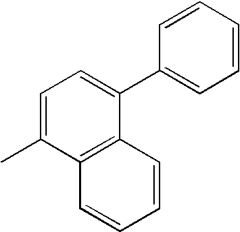 |
|
|
| 101 |
 |
 |
|
| 102 |
 |
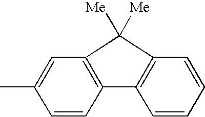 |
|
| 103 |
 |
 |
|
| 104 |
 |
 |
|
| 105 |
 |
|
|
| 106 |
 |
 |
|
| 107 |
 |
|
|
| 108 |
 |
 |
 |
| 109 |
 |
|
 |
| 110 |
|
|
|
| 111 |
|
|
|
| 112 |
|
 |
|
| 113 |
|
 |
|
| 114 |
|
 |
|
| 115 |
|
 |
|
| 116 |
|
 |
|
| 117 |
|
 |
|
| 118 |
|
|
 |
| 119 |
|
|
 |
| 120 |
 |
|
|
| 121 |
 |
 |
|
| 122 |
 |
|
|
| 123 |
 |
|
|
| 124 |
 |
 |
|
| 125 |
 |
 |
|
| 126 |
 |
 |
|
| 127 |
 |
 |
|
| 128 |
 |
|
|
| 129 |
 |
 |
|
| 130 |
 |
|
|
| 131 |
 |
 |
 |
| 132 |
 |
|
 |
| 133 |
 |
|
|
| 134 |
 |
 |
|
| 135 |
 |
|
|
| 136 |
 |
|
|
| 137 |
 |
 |
|
| 138 |
 |
 |
|
| 139 |
 |
 |
|
| 140 |
 |
 |
|
| 141 |
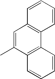 |
|
|
| 142 |
 |
 |
|
| 143 |
 |
|
|
| 144 |
 |
 |
 |
| 145 |
 |
|
 |
| 146 |
 |
|
|
| 147 |
 |
 |
|
| 148 |
 |
|
|
| 149 |
 |
|
|
| 150 |
 |
 |
|
| 151 |
 |
 |
|
| 152 |
 |
 |
|
| 153 |
 |
 |
|
| 154 |
 |
|
|
| 155 |
 |
 |
|
| 156 |
 |
|
|
| 157 |
 |
 |
 |
| 158 |
 |
|
 |
| 159 |
 |
|
|
| 160 |
 |
 |
|
| 161 |
 |
|
|
| 162 |
 |
|
|
| 163 |
 |
 |
|
| 164 |
 |
 |
|
| 165 |
 |
 |
|
| 166 |
 |
 |
|
| 167 |
 |
|
|
| 168 |
 |
 |
|
| 169 |
 |
|
|
| 170 |
 |
 |
 |
| 171 |
 |
|
 |
| 172 |
|
|
|
| 173 |
|
 |
|
| 174 |
|
|
|
| 175 |
|
 |
|
| 176 |
|
 |
|
| 177 |
|
 |
|
| 178 |
|
 |
|
| 179 |
|
|
|
| 180 |
|
 |
|
| 181 |
|
|
|
| 182 |
|
 |
 |
| 183 |
|
|
 |
| 184 |
 |
|
|
| 185 |
 |
 |
|
| 186 |
 |
|
|
| 187 |
 |
|
|
| 188 |
 |
 |
|
| 189 |
 |
 |
|
| 190 |
 |
 |
|
| 191 |
 |
|
|
| 192 |
 |
|
|
| 193 |
 |
|
|
| 194 |
 |
 |
 |
| 195 |
 |
|
 |
| 196 |
 |
|
|
| 197 |
 |
 |
|
| 198 |
 |
|
|
| 199 |
 |
|
|
| 200 |
 |
 |
|
| 201 |
 |
 |
|
| 202 |
 |
 |
|
| 203 |
 |
 |
|
| 204 |
 |
|
|
| 205 |
 |
 |
|
| 206 |
 |
|
|
| 207 |
 |
 |
 |
| 208 |
 |
|
 |
| 209 |
 |
|
|
| 210 |
 |
 |
|
| 211 |
 |
|
|
| 212 |
 |
|
|
| 213 |
 |
 |
|
| 214 |
 |
 |
|
| 215 |
 |
 |
|
| 216 |
 |
|
|
| 217 |
 |
 |
|
| 218 |
 |
|
|
| 219 |
 |
 |
 |
| 220 |
 |
|
 |
| 221 |
 |
|
|
| 222 |
 |
 |
|
| 223 |
 |
|
|
| 224 |
 |
|
|
| 225 |
 |
 |
|
| 226 |
 |
 |
|
| 227 |
 |
 |
|
| 228 |
 |
|
|
| 229 |
 |
 |
|
| 230 |
 |
|
|
| 231 |
 |
 |
 |
| 232 |
 |
|
 |
| 233 |
 |
|
|
| 234 |
 |
 |
|
| 235 |
 |
|
|
| 236 |
 |
|
|
| 237 |
 |
 |
|
| 238 |
 |
 |
|
| 239 |
 |
 |
|
| 240 |
 |
 |
|
| 241 |
 |
|
|
| 242 |
 |
 |
|
| 243 |
 |
|
|
| 244 |
 |
 |
 |
| 245 |
 |
|
 |

(in Formula (A), Ar8 is a group selected from phenyl, biphenyl, terphenyl, stilbene and distyrylaryl; Ar9 and Ar10 each are a hydrogen atom or an aromatic group having 6 to 20 carbon atoms, and Ar9 and Ar10 may be substituted; p′ is an integer of 1 to 4; and Ar9 and/or Ar10 are more preferably substituted with a styryl group).

(in Formula (B), Ar11 to Ar13 are an aryl group having 5 to 40 ring carbon atoms which may be substituted, and q′ is an integer of 1 to 4).
- (1) Anode/light emitting layer/cathode
- (2) Anode/hole injecting layer/light emitting layer/cathode
- (3) Anode/light emitting layer/electron injecting layer/cathode
- (4) Anode/hole injecting layer/light emitting layer/electron injecting layer/cathode
- (5) Anode/organic semiconductor layer/light emitting layer/cathode
- (6) Anode/organic semiconductor layer/electron barrier layer/light emitting layer/cathode
- (7) Anode/organic semi conductor layer/light emitting layer/adhesion improving layer/cathode
- (8) Anode/hole injecting layer/hole transporting layer/light emitting layer/electron injecting layer/cathode
- (9) Anode/insulating layer/light emitting layer/insulating layer/cathode
- (10) Anode/inorganic semiconductor layer/insulating layer/light emitting layer/insulating layer/cathode
- (11) Anode/organic semiconductor layer/insulating layer/light emitting layer/insulating layer/cathode
- (12) Anode/insulating layer/hole injecting layer/hole transporting layer/light emitting layer/insulating layer/cathode
- (13) Anode/insulating layer/hole injecting layer/hole transporting layer/light emitting layer/electron injecting layer/cathode

(wherein Ar is a substituted or non-substituted fused aromatic group having 10 to 50 ring carbon atoms;
Ar′ is a substituted or non-substituted aromatic group having 6 to 50 ring carbon atoms;
X is a substituted or non-substituted aromatic group having 6 to 50 ring carbon atoms, a substituted or non-substituted aromatic heterocyclic group having 5 to 50 ring carbon atoms, a substituted or non-substituted alkyl group having 1 to 50 carbon atoms, a substituted or non-substituted alkoxy group having 1 to 50 carbon atoms, a substituted or non-substituted aralkyl group having 6 to 50 carbon atoms, a substituted or non-substituted aryloxy group having 5 to 50 ring carbon atoms, a substituted or non-substituted arylthio group having 5 to 50 ring carbon atoms, a substituted or non-substituted alkoxycarbonyl group having 1 to 50 carbon atoms, a carboxyl group, a halogen atom, a cyano group, a nitro group or a hydroxyl group;
a, b and c each are an integer of 0 to 4
n is an integer of 1 to 3 and when n is 2 or more, an inside of a parenthesis may be the same or different).

(wherein Ar1 and Ar2 each are independently a substituted or non-substituted aromatic ring group having 6 to 50 ring carbon atoms; m and n each are an integer of 1 to 4; provided that when m and n are 1 and the positions of Ar1 and Ar2 bonded to the benzene ring are bilaterally symmetric, Ar1 and Ar2 are not the same, and when m and n are an integer of 2 to 4, m and n are different integers; and
R1 to R10 each are independently a hydrogen atom, a substituted or non-substituted aromatic ring group having 6 to 50 ring carbon atoms, a substituted or non-substituted aromatic heterocyclic group having 5 to 50 ring carbon atoms, a substituted or non-substituted alkyl group having 1 to 50 carbon atoms, a substituted or non-substituted cycloalkyl group, a substituted or non-substituted alkoxy group having 1 to 50 carbon atoms, a substituted or non-substituted aralkyl group having 6 to 50 carbon atoms, a substituted or non-substituted aryloxy group having 5 to 50 ring carbon atoms, a substituted or non-substituted arylthio group having 5 to 50 ring carbon atoms, a substituted or non-substituted alkoxycarbonyl group having 1 to 50 carbon atoms, a substituted or non-substituted silyl group, a carboxyl group, a halogen atom, a cyano group, a nitro group or a hydroxyl group).

(wherein Ar and Ar′ each are a substituted or non-substituted aromatic group having 6 to 50 ring carbon atoms;
L and L′ each are a substituted or non-substituted phenylene group, a substituted or non-substituted naphthalenylene group, a substituted or non-substituted fluorenylene group or a substituted or non-substituted dibenzosilolylene group;
m is an integer of 0 to 2; n is an integer of 1 to 4; s is an integer of 0 to 2; and t is an integer of 0 to 4;
L or Ar is bonded to any of 1- to 5-positions of pyrene, and L′ or Ar′ is bonded to any of 6- to 10-positions of pyrene;
provided that when n+t is an even number, Ar, Ar′, L and L′ satisfy (1) or (2) described below;
(1) Ar≠Ar′ and/or L≠L′ (in this case, shows that both are groups having different structures) and
(2) when Ar=Ar′ and L=L′,

(wherein A1 and A2 each are independently a substituted or non-substituted fused aromatic group having 10 to 20 ring carbon atoms;
Ar1 and Ar2 each are independently a hydrogen atom or a substituted or non-substituted aromatic ring group having 6 to 50 ring carbon atoms;
R1 to R10 each are independently a hydrogen atom, a substituted or non-substituted aromatic ring group having 6 to 50 ring carbon ring atoms, a substituted or non-substituted aromatic heterocyclic group having 5 to 50 ring carbon atoms, a substituted or non-substituted alkyl group having 1 to 50 carbon atoms, a substituted or non-substituted cycloalkyl group, a substituted or non-substituted alkoxy group having 1 to 50 carbon atoms, a substituted or non-substituted aralkyl group having 6 to 50 carbon atoms, a substituted or non-substituted aryloxy group having 5 to 50 ring carbon atoms, a substituted or non-substituted arylthio group having 5 to 50 ring carbon atoms, a substituted or non-substituted alkoxycarbonyl group having 1 to 50 carbon atoms, a substituted or non-substituted silyl group, a carboxyl group, a halogen atom, a cyano group, a nitro group or a hydroxyl group;
Ar1, Ar2, R9 and R10 each may be plural, and the adjacent groups may form a saturated or unsaturated cyclic structure;
provided that there is no case in which in Formula (1), the groups which are symmetric to an X-Y axis shown on anthracene in a center are bonded to a 9-position and a re-position of the above anthracene).

(wherein R1 to R10 each represent independently a hydrogen atom, an alkyl group, a cycloalkyl group, as aryl group which may be substituted, an alkoxyl group, an aryloxy group, an alkylamino group, an alkenyl group, an arylamino group or a heterocyclic group which may be substituted; a and b each represent an integer of 1 to 5; when they are 2or more, R1's themselves or R2's themselves each may be the same as or different from each other, and R1's themselves or R2's themselves may be combined with each other to form a ring; R3 and R4, R5 and R6, R7 and R8 and R9 and R10 may be combined with each other to form, rings; and L1 represents a single bond, —O—, —S—, —N(R)— (R is an alkyl group or an aryl group which may be substituted), an alkylene group or an arylene group).

(wherein R11 to R20 each represent independently a hydrogen atom, an alkyl group, a cycloalkyl group, an aryl group, an alkoxyl group, an aryloxy group, an alkylamino group, an arylamino group or a heterocyclic group which may be substituted; c, d, e and f each represent an integer of 1 to 5; when they are 2 or more, R11's themselves, R12's themselves, R16's themselves or R17's themselves may be the same as or different from each other, and R11's themselves, R12's themselves, R16's themselves or R17's themselves may be combined with each other to form a ring; R13 and R14 and R18 and R19 may be combined with each other to form rings; and L2 represents a single bond, —O—, —S—, —N(R)— (R is an alkyl group or an aryl group which may be substituted), an alkylene group or an arylene group).

(wherein A5 to A8 each are independently a substituted or non-substituted biphenyl group or a substituted or non substituted naphthyl group).

(wherein A9 to A14 are the same as those described above; R21 to R23 each represent independently a hydrogen atom, an alkyl group having 1 to 6 carbon atoms, a cycloalkyl group having 3 to 6 carbon atoms, an alkoxyl group having 1 to 6 carbon atoms, an aryloxy group having 5 to 18 carbon atoms, an aralkyloxy group having 7 to 18 carbon atoms, an arylamino group having 5 to 16 carbon atoms, a nitro group, a cyano group, an ester group having 1 to 6 carbon atoms or a halogen atom; and at least one of A9 to A14 is a group having 3 or more fused aromatic rings).

(wherein R1 and R2 represent a hydrogen atom, a substituted or non-substituted alkyl group, a substituted or non-substituted aralkyl group, a substituted or non-substituted aryl group, a substituted or non-substituted heterocyclic group, a substituted amino group, a cyano group or a halogen atom; R1's themselves and R2's themselves which are bonded to the different fluorene groups may be the same as or different from each other, and R1 and R2 which are bonded to the same fluorene group may be the same or different; R3 and R4 represent a hydrogen atom, a substituted or non-substituted alkyl group, a substituted or non-substituted aralkyl group, a substituted or non-substituted aryl group or a substituted or non-substituted heterocyclic group; R3's themselves and R4's themselves which are bonded to the different fluorene groups may be the same as or different from each other, and R3 and R4 which are bonded to the same fluorene group may be the same or different; Ar1 and Ar2 represent a substituted or non-substituted fused polycyclic aromatic group in which the total of benzene rings is 3 or more or a fused polycyclic heterocyclic group in which the total of benzene rings and heterocycles is 3 or more and which is bonded to the fluorene group via substituted or non-substituted, carbon; Ar1 and Ar2 may be the same or different; and n represents an integer of 1 to 10).


(wherein Ar1, Ar2, Ar3, Ar5, Ar6 and Ar9 each represent a substituted or non-substituted aryl group, and they may be the same as or different from each other; Ar4, Ar7 and Ar8 each represent a substituted or non-substituted arylene group, and they may be the same as or different from each other).


(in formulas (A) and (b), A1 to A3 each are independently a nitrogen atom or an oxygen atom;
Ar1 is a substituted or non-substituted aryl group having 6 to 60 ring carbon atoms or a substituted or non-substituted heteroaryl group having 3 to 60 ring carbon atoms; Ar2 is a hydrogen atom, a substituted or non-substituted aryl group having 6 to 60 ring carbon atoms, a substituted or non-substituted heteroaryl group having 3 to 60 ring carbon atoms, a substituted or non-substituted alkyl group having 1 to 20 carbon atoms or a substituted or non-substituted alkoxy group having 1 to 20 carbon atoms or a divalent group thereof; provided that any one of Ar1 and Ar2 is a substituted or non-substituted fused ring group having 10 to 60 ring carbon atoms or a substituted or non-substituted monohetero fused ring group having 3 to 60 ring carbon atoms;
L1, L2 and L each are independently a single bond, a substituted or non-substituted arylene group having 6 to 60 ring carbon atoms, a substituted or non-substituted heteroarylene group having 3 to 60 ring-carbon atoms or a substituted or non-substituted fluorenylene group;
R is a hydrogen atom, a substituted or non-substituted aryl group having 6 to 60 ring carbon atoms, a substituted or non-substituted heteroaryl group having 3 to 60 ring carbon atoms, a substituted or non-substituted alkyl group having 1 to 20 carbon atoms or a substituted or non-substituted alkoxy group having 1 to 20 carbon atoms; n is an integer of 0 to 5; when n is 2 or more, plural R's may be the same or different, and adjacent plural R's may be combined with each other to form a carbocyclic aliphatic ring or a carbocyclic aromatic ring).
HAr-L-Ar1—Ar2 (C)
(wherein HAr is a nitrogen-containing heterocycle having 3 to 40 carbon atoms which may have a substituent; L is a single bond, an arylene group having 6 to 60 carbon atoms which may have a substituent, a heteroarylene group having 3 to 60 carbon atoms which may have a substituent or a fluorenylene group which may have a substituent; Ar1 is a divalent aromatic hydrocarbon group having 6 to 60 carbon atoms which may have a substituent; and Ar3 is an aryl group having 6 to 60 carbon atoms which may have a substituent or a heteroaryl group having 3 to 60 carbon atoms which may have a substituent).

(wherein X and Y each are independently a saturated or unsaturated hydrocarbon group having 1 to 6′ carbon atoms, an alkoxy group, an alkenyloxy group, an alkynyloxy group, a hydroxy group, a substituted or non-substituted aryl group, a substituted or non-substituted heterocycle or a structure in which X is combined with Y to form a saturated or unsaturated ring; R1 to R4 each are independently a hydrogen atom, a halogen atom, a substituted or non-substituted alkyl group having 1 to 6 carbon atoms, an alkoxy group, an aryloxy group, a perfluoroalkyl group, a perfluoroalkoxy group, an amino group, an alkyl-carbonyl group, an arylcarbonyl group, an alkoxycarbonyl group, an aryloxycarbonyl group, an azo group, an alkylcarbonyloxy group, an arylcarbonyloxy group, an alkoxycarbonyloxy group, an aryloxycarbonyloxy group, a sulfinyl group, a sulfonyl group, a sulfanyl group, a silyl group, a carbamoyl group, an aryl group, a heterocyclic group, an alkenyl group, an alkynyl group, a nitro group, a formyl group, a nitroso group, a formyloxy group, an isocyano group, a cyanate group, an isocyanate group, a thiocyanate group, an isothiocyanate group, a cyano group or a structure in which substituted or non-substituted rings are fused when they are adjacent).

(wherein R1 to R8 and Z2 each represent independently a hydrogen atom, a saturated or unsaturated hydrocarbon group, an aromatic group, a heterocyclic group, a substituted amino group, a substituted boryl group, an alkoxy group or an aryloxy group; X, Y and Z1 each represent independently a saturated or unsaturated hydrocarbon group, an aromatic group, a heterocyclic group, a substituted amino group, an alkoxy group or an aryloxy group; substituents of Z1 and Z2 may be combined with each other to form a fused ring; n represents an integer of 1 to 3, and when n is 2 or more, Z1's may be different; provided that a case in which n is 1 and X, Y and R2 are methyl and in which R8 is a hydrogen atom or a substituted boryl group and a case in which n is 3 and Z1 is methyl are not included).

[wherein Q1 and Q2 each represent independently a ligand represented by the following Formula (G), and L represents a halogen atom, a substituted or non-substituted alkyl group, a substituted or non-substituted cycloalkyl group, a substituted or non-substituted aryl group, a substituted or non-substituted heterocyclic group, —OR1 (R1 is a hydrogen atom, a substituted or non-substituted alkyl group, a substituted or non-substituted cycloalkyl group, a substituted or non-substituted aryl group or a substituted or non-substituted heterocyclic group) or a ligand represented by —O—Ga-Q3(Q4) (Q3 and Q4 are the same as Q1 and Q2)]:

[wherein rings A1 and A2 assume a six-membered aryl ring structure which may have a substituent and in which they are fused with each other].


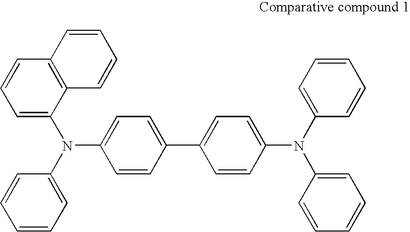
| TABLE 1 | |||||
| Hole | Current | Half | |||
| transporting | efficiency | Luminescent | lifetime | ||
| material | (cd/A) | color | (hour) | ||
| Example 1 | H1 | 5.1 | blue | 420 |
| Example 2 | H2 | 4.8 | blue | 390 |
| Example 3 | H3 | 5.4 | blue | 370 |
| Example 4 | H4 | 5.0 | blue | 410 |
| Example 5 | H5 | 4.9 | blue | 350 |
| Example 6 | H6 | 5.0 | blue | 360 |
| Example 7 | H7 | 5.1 | blue | 340 |
| Example 8 | H8 | 5.2 | blue | 330 |
| Example 9 | H9 | 4.9 | blue | 400 |
| Example 10 | H10 | 4.8 | blue | 420 |
| Example 11 | H11 | 4.9 | blue | 400 |
| Example 12 | H12 | 5.0 | blue | 410 |
| Example 13 | H13 | 5.2 | blue | 330 |
| Example 14 | H14 | 5.4 | blue | 340 |
| Comparative | Comparative | 4.8 | blue | 280 |
| Example 1 | compound 1 | |||

Claims (10)
A-L-B (1)


Applications Claiming Priority (3)
| Application Number | Priority Date | Filing Date | Title |
|---|---|---|---|
| JP2005-000639 | 2005-01-05 | ||
| JP2005000639 | 2005-01-05 | ||
| PCT/JP2005/023494 WO2006073059A1 (en) | 2005-01-05 | 2005-12-21 | Aromatic amine derivative and organic electroluminescent device using same |
Publications (2)
| Publication Number | Publication Date |
|---|---|
| US20080108811A1 US20080108811A1 (en) | 2008-05-08 |
| US8629613B2 true US8629613B2 (en) | 2014-01-14 |
Family
ID=36647542
Family Applications (1)
| Application Number | Title | Priority Date | Filing Date |
|---|---|---|---|
| US11/813,394 Expired - Fee Related US8629613B2 (en) | 2005-01-05 | 2005-12-21 | Aromatic amine derivative and organic electroluminescent device using same |
Country Status (7)
| Country | Link |
|---|---|
| US (1) | US8629613B2 (en) |
| EP (1) | EP1834946A4 (en) |
| JP (1) | JP4955402B2 (en) |
| KR (1) | KR20070091183A (en) |
| CN (1) | CN101094828A (en) |
| TW (1) | TW200639229A (en) |
| WO (1) | WO2006073059A1 (en) |
Cited By (2)
| Publication number | Priority date | Publication date | Assignee | Title |
|---|---|---|---|---|
| US10804471B2 (en) | 2008-05-16 | 2020-10-13 | Semiconductor Energy Laboratory Co., Ltd. | Triarylamine derivative, light-emitting substance, light-emitting element, light-emitting device, and electronic device |
| US11024805B2 (en) * | 2016-05-04 | 2021-06-01 | Duk San Neolux Co., Ltd. | Compound for organic electric element, organic electric element using same, and electronic device thereof |
Families Citing this family (22)
| Publication number | Priority date | Publication date | Assignee | Title |
|---|---|---|---|---|
| KR20120039057A (en) | 2005-01-05 | 2012-04-24 | 이데미쓰 고산 가부시키가이샤 | Aromatic amine derivative and organic electroluminescent device using same |
| JP5040062B2 (en) * | 2005-01-17 | 2012-10-03 | コニカミノルタホールディングス株式会社 | Organic electroluminescence element, lighting device and display device |
| WO2007058127A1 (en) * | 2005-11-16 | 2007-05-24 | Idemitsu Kosan Co., Ltd. | Aromatic amine derivative and organic electroluminescent element using the same |
| WO2007148660A1 (en) | 2006-06-22 | 2007-12-27 | Idemitsu Kosan Co., Ltd. | Organic electroluminescent device employing heterocycle-containing arylamine derivative |
| KR20090023411A (en) * | 2006-06-27 | 2009-03-04 | 이데미쓰 고산 가부시키가이샤 | Aromatic Amine Derivatives and Organic Electroluminescent Devices Using Them |
| KR20090040896A (en) * | 2006-08-23 | 2009-04-27 | 이데미쓰 고산 가부시키가이샤 | Aromatic amine derivatives and organic electroluminescent devices using them |
| JP2008069120A (en) * | 2006-09-15 | 2008-03-27 | Idemitsu Kosan Co Ltd | Aromatic amine derivatives and organic electroluminescence devices using them |
| WO2008105294A1 (en) * | 2007-02-28 | 2008-09-04 | Idemitsu Kosan Co., Ltd. | Organic el device |
| US20100187511A1 (en) * | 2007-06-18 | 2010-07-29 | Idemitsu Kosan Co., Ltd. | Aromatic amine derivative and organic electroluminescent device using the same |
| KR20140106740A (en) * | 2007-12-03 | 2014-09-03 | 가부시키가이샤 한도오따이 에네루기 켄큐쇼 | Carbazole derivative, and light-emitting element, light-emitting device, and electronic device using carbazole derivative |
| KR20100116180A (en) * | 2008-02-04 | 2010-10-29 | 이데미쓰 고산 가부시키가이샤 | Aromatic amine derivative and organic electroluminescent device using the same |
| KR101050459B1 (en) * | 2008-09-03 | 2011-07-20 | 삼성모바일디스플레이주식회사 | Fluorene Compound and Organic Electroluminescent Device Using the Same |
| CN102414164A (en) | 2009-04-24 | 2012-04-11 | 出光兴产株式会社 | Aromatic amine derivative and organic electroluminescent device using the same |
| TW201139402A (en) * | 2010-01-21 | 2011-11-16 | Idemitsu Kosan Co | Aromatic amine derivative, and organic electroluminescent element comprising same |
| KR101111413B1 (en) * | 2011-06-29 | 2012-02-15 | 덕산하이메탈(주) | Organic Electrical Devices, New Compounds and Compositions for Organic Electrical Devices Using Diarylamine Derivatives |
| DE102012007795B3 (en) * | 2012-04-20 | 2013-02-21 | Novaled Ag | New aryl amine-terphenyl compounds useful in an organic semiconductive device, preferably organic LED or a photovoltaic device, preferably solar cell |
| JP6307689B2 (en) | 2012-12-05 | 2018-04-11 | 三星ディスプレイ株式會社Samsung Display Co.,Ltd. | AMINE DERIVATIVE, ORGANIC LIGHT EMITTING MATERIAL AND ORGANIC ELECTROLUMINESCENT DEVICE USING THE SAME |
| KR102115477B1 (en) | 2013-08-14 | 2020-05-27 | 삼성디스플레이 주식회사 | Organic compound and organic light emitting diode device including the same |
| KR101892234B1 (en) | 2014-10-31 | 2018-08-27 | 삼성에스디아이 주식회사 | Organic optoelectric device and display device |
| JP2016100364A (en) | 2014-11-18 | 2016-05-30 | 三星ディスプレイ株式會社Samsung Display Co.,Ltd. | Material for organic electroluminescence device and organic electroluminescence device using the same |
| KR101842749B1 (en) * | 2015-10-28 | 2018-03-27 | 난징고광반도체재료유한회사 | Blue fluorescent host materials, and organic thin film and organic light emitting devices comprising the same |
| CN110483495B (en) * | 2019-09-16 | 2020-04-28 | 长春海谱润斯科技有限公司 | A kind of heterocyclic compound and its organic electroluminescent device |
Citations (24)
| Publication number | Priority date | Publication date | Assignee | Title |
|---|---|---|---|---|
| JPH04195487A (en) | 1990-11-28 | 1992-07-15 | Hitachi Ltd | Information processor for information module with display |
| JPH0611854A (en) | 1992-06-25 | 1994-01-21 | Konica Corp | Electrophotographic sensitive body |
| JPH07175237A (en) | 1993-11-01 | 1995-07-14 | Ricoh Co Ltd | Electrophotographic photoconductor |
| JPH08302341A (en) | 1995-04-27 | 1996-11-19 | Ricoh Co Ltd | Organic EL element |
| US5759444A (en) * | 1995-09-25 | 1998-06-02 | Toyo Ink Manufacturing Co., Ltd. | Light-emitting material for organic electroluminescence device, and organic electroluminescence device for which the light-emitting material is adapted |
| US5792557A (en) * | 1994-02-08 | 1998-08-11 | Tdk Corporation | Organic EL element |
| JPH1135532A (en) | 1997-05-19 | 1999-02-09 | Canon Inc | Organic compound and light emitting device using the organic compound |
| US6074734A (en) * | 1995-01-19 | 2000-06-13 | Idemitsu Kosan Co., Ltd. | Organic electroluminescence device, organic thin film, and triamine compound |
| US20020015860A1 (en) * | 2000-02-18 | 2002-02-07 | Toshihiko Motomatsu | Organic electroluminescent element and organic electroluminescent display |
| WO2002088274A1 (en) | 2001-04-27 | 2002-11-07 | Lg Chem, Ltd. | Double-spiro organic compounds and electroluminescent devices |
| JP2003089682A (en) | 2001-09-19 | 2003-03-28 | Mitsui Chemicals Inc | Amine compound and organic electroluminescence element comprising the same |
| US6632543B1 (en) * | 1999-09-30 | 2003-10-14 | Idemitsu Kosan Co., Ltd. | Amine compound and organic electroluminescence device using the compound |
| WO2004041774A1 (en) | 2002-11-06 | 2004-05-21 | Idemitsu Kosan Co., Ltd. | Aromatic amine derivative and organic electroluminescent element employing the same |
| JP2004262761A (en) | 2003-01-16 | 2004-09-24 | Idemitsu Kosan Co Ltd | Aromatic amine derivative and organic electroluminescent device using the same |
| WO2004101491A1 (en) | 2003-05-15 | 2004-11-25 | Idemitsu Kosan Co. Ltd. | Arylamine compound and organic electroluminescence device containing the same |
| US20050067951A1 (en) * | 2002-01-28 | 2005-03-31 | Sensient Imaging Technologies Gmbh | Triarylamine derivatives and their use in organic electroluminescent and electrophotographic devices |
| JP2005120030A (en) | 2003-10-17 | 2005-05-12 | Mitsui Chemicals Inc | 9,9-diphenylfluorene compound and organic electroluminescent device containing the 9,9-diphenylfluorene compound |
| JP2005216683A (en) | 2004-01-29 | 2005-08-11 | Tdk Corp | COMPOUND FOR ORGANIC EL ELEMENT AND ORGANIC EL ELEMENT |
| US20060159957A1 (en) * | 2004-07-14 | 2006-07-20 | Idemitsu Kosan Co., Ltd. | Aromatic amine derivative and organic electroluminescence device employing the same |
| JP2006233162A (en) | 2004-03-11 | 2006-09-07 | Mitsubishi Chemicals Corp | Charge transport film composition and ionic compound, charge transport film and organic electroluminescent device using the same, method for producing organic electroluminescent device, and method for producing charge transport film |
| US20070111028A1 (en) | 2005-11-15 | 2007-05-17 | Idemitsu Kosan Co., Ltd. | Aromatic amine derivative and organic electroluminescence device using the same |
| US20070145888A1 (en) | 2005-11-16 | 2007-06-28 | Idemitsu Kosan Co., Ltd. | Aromatic amine derivatives and organic electroluminescence device using the same |
| EP1806334A1 (en) | 2004-10-29 | 2007-07-11 | Idemitsu Kosan Co., Ltd. | Aromatic amine compound and organic electroluminescent device using same |
| JP4195487B2 (en) | 2005-01-05 | 2008-12-10 | 出光興産株式会社 | Aromatic amine derivative and organic electroluminescence device using the same |
Family Cites Families (1)
| Publication number | Priority date | Publication date | Assignee | Title |
|---|---|---|---|---|
| JP2004288640A (en) * | 1993-09-29 | 2004-10-14 | Idemitsu Kosan Co Ltd | Organic electroluminescence device |
-
2005
- 2005-12-21 WO PCT/JP2005/023494 patent/WO2006073059A1/en not_active Ceased
- 2005-12-21 US US11/813,394 patent/US8629613B2/en not_active Expired - Fee Related
- 2005-12-21 EP EP05820105A patent/EP1834946A4/en not_active Withdrawn
- 2005-12-21 CN CNA2005800459026A patent/CN101094828A/en active Pending
- 2005-12-21 JP JP2006550712A patent/JP4955402B2/en not_active Expired - Fee Related
- 2005-12-21 KR KR1020077015337A patent/KR20070091183A/en not_active Ceased
- 2005-12-27 TW TW094146780A patent/TW200639229A/en unknown
Patent Citations (27)
| Publication number | Priority date | Publication date | Assignee | Title |
|---|---|---|---|---|
| JPH04195487A (en) | 1990-11-28 | 1992-07-15 | Hitachi Ltd | Information processor for information module with display |
| JPH0611854A (en) | 1992-06-25 | 1994-01-21 | Konica Corp | Electrophotographic sensitive body |
| JPH07175237A (en) | 1993-11-01 | 1995-07-14 | Ricoh Co Ltd | Electrophotographic photoconductor |
| US5792557A (en) * | 1994-02-08 | 1998-08-11 | Tdk Corporation | Organic EL element |
| US6074734A (en) * | 1995-01-19 | 2000-06-13 | Idemitsu Kosan Co., Ltd. | Organic electroluminescence device, organic thin film, and triamine compound |
| JPH08302341A (en) | 1995-04-27 | 1996-11-19 | Ricoh Co Ltd | Organic EL element |
| US5759444A (en) * | 1995-09-25 | 1998-06-02 | Toyo Ink Manufacturing Co., Ltd. | Light-emitting material for organic electroluminescence device, and organic electroluminescence device for which the light-emitting material is adapted |
| JPH1135532A (en) | 1997-05-19 | 1999-02-09 | Canon Inc | Organic compound and light emitting device using the organic compound |
| US6632543B1 (en) * | 1999-09-30 | 2003-10-14 | Idemitsu Kosan Co., Ltd. | Amine compound and organic electroluminescence device using the compound |
| US20020015860A1 (en) * | 2000-02-18 | 2002-02-07 | Toshihiko Motomatsu | Organic electroluminescent element and organic electroluminescent display |
| WO2002088274A1 (en) | 2001-04-27 | 2002-11-07 | Lg Chem, Ltd. | Double-spiro organic compounds and electroluminescent devices |
| JP2003089682A (en) | 2001-09-19 | 2003-03-28 | Mitsui Chemicals Inc | Amine compound and organic electroluminescence element comprising the same |
| US20050067951A1 (en) * | 2002-01-28 | 2005-03-31 | Sensient Imaging Technologies Gmbh | Triarylamine derivatives and their use in organic electroluminescent and electrophotographic devices |
| WO2004041774A1 (en) | 2002-11-06 | 2004-05-21 | Idemitsu Kosan Co., Ltd. | Aromatic amine derivative and organic electroluminescent element employing the same |
| US20060061265A1 (en) | 2002-11-06 | 2006-03-23 | Hisayuki Kawamura | Aromatic amine derivative and organic electroluminescent element employing the same |
| JP2004262761A (en) | 2003-01-16 | 2004-09-24 | Idemitsu Kosan Co Ltd | Aromatic amine derivative and organic electroluminescent device using the same |
| US20060134458A1 (en) * | 2003-01-16 | 2006-06-22 | Hisayuki Kawamura | Aromatic amine derivative and organic electroluminescence element |
| US20070018569A1 (en) | 2003-05-15 | 2007-01-25 | Idemitsu Kosan Co., Ltd. | Arylamine compound and organic electroluminescence device containing the same |
| WO2004101491A1 (en) | 2003-05-15 | 2004-11-25 | Idemitsu Kosan Co. Ltd. | Arylamine compound and organic electroluminescence device containing the same |
| JP2005120030A (en) | 2003-10-17 | 2005-05-12 | Mitsui Chemicals Inc | 9,9-diphenylfluorene compound and organic electroluminescent device containing the 9,9-diphenylfluorene compound |
| JP2005216683A (en) | 2004-01-29 | 2005-08-11 | Tdk Corp | COMPOUND FOR ORGANIC EL ELEMENT AND ORGANIC EL ELEMENT |
| JP2006233162A (en) | 2004-03-11 | 2006-09-07 | Mitsubishi Chemicals Corp | Charge transport film composition and ionic compound, charge transport film and organic electroluminescent device using the same, method for producing organic electroluminescent device, and method for producing charge transport film |
| US20060159957A1 (en) * | 2004-07-14 | 2006-07-20 | Idemitsu Kosan Co., Ltd. | Aromatic amine derivative and organic electroluminescence device employing the same |
| EP1806334A1 (en) | 2004-10-29 | 2007-07-11 | Idemitsu Kosan Co., Ltd. | Aromatic amine compound and organic electroluminescent device using same |
| JP4195487B2 (en) | 2005-01-05 | 2008-12-10 | 出光興産株式会社 | Aromatic amine derivative and organic electroluminescence device using the same |
| US20070111028A1 (en) | 2005-11-15 | 2007-05-17 | Idemitsu Kosan Co., Ltd. | Aromatic amine derivative and organic electroluminescence device using the same |
| US20070145888A1 (en) | 2005-11-16 | 2007-06-28 | Idemitsu Kosan Co., Ltd. | Aromatic amine derivatives and organic electroluminescence device using the same |
Non-Patent Citations (2)
| Title |
|---|
| Office Action issued Jun. 21, 2011, in Japanese Patent Application No. 2006-550712. |
| U.S. Appl. No. 13/345,536, filed Jan. 6, 2012, Yabunouchi, et al. |
Cited By (5)
| Publication number | Priority date | Publication date | Assignee | Title |
|---|---|---|---|---|
| US10804471B2 (en) | 2008-05-16 | 2020-10-13 | Semiconductor Energy Laboratory Co., Ltd. | Triarylamine derivative, light-emitting substance, light-emitting element, light-emitting device, and electronic device |
| US11678568B2 (en) | 2008-05-16 | 2023-06-13 | Semiconductor Energy Laboratory Co., Ltd. | Triarylamine derivative, light-emitting substance, light-emitting element, light-emitting device, and electronic device |
| US11980087B2 (en) | 2008-05-16 | 2024-05-07 | Semiconductor Energy Laboratory Co., Ltd. | Triarylamine derivative, light-emitting substance, light-emitting element, light-emitting device, and electronic device |
| US12490650B2 (en) | 2008-05-16 | 2025-12-02 | Semiconductor Energy Laboratory Co., Ltd. | Triarylamine derivative, light-emitting substance, light-emitting element, light-emitting device, and electronic device |
| US11024805B2 (en) * | 2016-05-04 | 2021-06-01 | Duk San Neolux Co., Ltd. | Compound for organic electric element, organic electric element using same, and electronic device thereof |
Also Published As
| Publication number | Publication date |
|---|---|
| TW200639229A (en) | 2006-11-16 |
| KR20070091183A (en) | 2007-09-07 |
| CN101094828A (en) | 2007-12-26 |
| WO2006073059A1 (en) | 2006-07-13 |
| US20080108811A1 (en) | 2008-05-08 |
| EP1834946A4 (en) | 2009-04-29 |
| EP1834946A8 (en) | 2008-05-14 |
| JP4955402B2 (en) | 2012-06-20 |
| EP1834946A1 (en) | 2007-09-19 |
| JPWO2006073059A1 (en) | 2008-06-12 |
Similar Documents
| Publication | Publication Date | Title |
|---|---|---|
| US11751472B2 (en) | Aromatic amine derivative and elecroluminescence device using the same | |
| US8129038B2 (en) | Aromatic amine derivative and electroluminescence device using the same | |
| US7834346B2 (en) | Nitrogenous heterocyclic derivative and organic electroluminescence device making use of the same | |
| KR101169901B1 (en) | Aromatic amine derivative and organic electroluminescent device using same | |
| US8512878B2 (en) | Diaminopyrene derivative and organic EL device using the same | |
| US8629613B2 (en) | Aromatic amine derivative and organic electroluminescent device using same | |
| US7838130B2 (en) | Aminodibenzofluorene derivative and organic electroluminescence device using the same | |
| US20070296331A1 (en) | Aromatic amine derivative and organic electroluminescence device using the same | |
| KR101026627B1 (en) | Aromatic Amine Derivatives and Organic Electroluminescent Devices Using The Same | |
| KR20080067344A (en) | Aromatic Amine Derivatives and Organic Electroluminescent Devices Using The Same |
Legal Events
| Date | Code | Title | Description |
|---|---|---|---|
| AS | Assignment |
Owner name: IDEMITSU KOSAN CO., LTD., JAPAN Free format text: ASSIGNMENT OF ASSIGNORS INTEREST;ASSIGNORS:YABUNOUCHI, NOBUHIRO;KAWAMURA, HISAYUKI;REEL/FRAME:019519/0485 Effective date: 20070618 |
|
| STCF | Information on status: patent grant |
Free format text: PATENTED CASE |
|
| FEPP | Fee payment procedure |
Free format text: PAYOR NUMBER ASSIGNED (ORIGINAL EVENT CODE: ASPN); ENTITY STATUS OF PATENT OWNER: LARGE ENTITY |
|
| FPAY | Fee payment |
Year of fee payment: 4 |
|
| FEPP | Fee payment procedure |
Free format text: MAINTENANCE FEE REMINDER MAILED (ORIGINAL EVENT CODE: REM.); ENTITY STATUS OF PATENT OWNER: LARGE ENTITY |
|
| LAPS | Lapse for failure to pay maintenance fees |
Free format text: PATENT EXPIRED FOR FAILURE TO PAY MAINTENANCE FEES (ORIGINAL EVENT CODE: EXP.); ENTITY STATUS OF PATENT OWNER: LARGE ENTITY |
|
| STCH | Information on status: patent discontinuation |
Free format text: PATENT EXPIRED DUE TO NONPAYMENT OF MAINTENANCE FEES UNDER 37 CFR 1.362 |
|
| FP | Lapsed due to failure to pay maintenance fee |
Effective date: 20220114 |