US8623306B2 - Method for use in connection with an exhaust gas post-treatment system - Google Patents
Method for use in connection with an exhaust gas post-treatment system Download PDFInfo
- Publication number
- US8623306B2 US8623306B2 US13/733,252 US201313733252A US8623306B2 US 8623306 B2 US8623306 B2 US 8623306B2 US 201313733252 A US201313733252 A US 201313733252A US 8623306 B2 US8623306 B2 US 8623306B2
- Authority
- US
- United States
- Prior art keywords
- emissions
- untreated
- exhaust gas
- catalyst
- reducing agent
- Prior art date
- Legal status (The legal status is an assumption and is not a legal conclusion. Google has not performed a legal analysis and makes no representation as to the accuracy of the status listed.)
- Active
Links
Images


Classifications
-
- B—PERFORMING OPERATIONS; TRANSPORTING
- B01—PHYSICAL OR CHEMICAL PROCESSES OR APPARATUS IN GENERAL
- B01D—SEPARATION
- B01D53/00—Separation of gases or vapours; Recovering vapours of volatile solvents from gases; Chemical or biological purification of waste gases, e.g. engine exhaust gases, smoke, fumes, flue gases, aerosols
- B01D53/34—Chemical or biological purification of waste gases
- B01D53/92—Chemical or biological purification of waste gases of engine exhaust gases
- B01D53/94—Chemical or biological purification of waste gases of engine exhaust gases by catalytic processes
- B01D53/9404—Removing only nitrogen compounds
- B01D53/9409—Nitrogen oxides
-
- F—MECHANICAL ENGINEERING; LIGHTING; HEATING; WEAPONS; BLASTING
- F01—MACHINES OR ENGINES IN GENERAL; ENGINE PLANTS IN GENERAL; STEAM ENGINES
- F01N—GAS-FLOW SILENCERS OR EXHAUST APPARATUS FOR MACHINES OR ENGINES IN GENERAL; GAS-FLOW SILENCERS OR EXHAUST APPARATUS FOR INTERNAL-COMBUSTION ENGINES
- F01N2430/00—Influencing exhaust purification, e.g. starting of catalytic reaction, filter regeneration, or the like, by controlling engine operating characteristics
- F01N2430/06—Influencing exhaust purification, e.g. starting of catalytic reaction, filter regeneration, or the like, by controlling engine operating characteristics by varying fuel-air ratio, e.g. by enriching fuel-air mixture
-
- F—MECHANICAL ENGINEERING; LIGHTING; HEATING; WEAPONS; BLASTING
- F01—MACHINES OR ENGINES IN GENERAL; ENGINE PLANTS IN GENERAL; STEAM ENGINES
- F01N—GAS-FLOW SILENCERS OR EXHAUST APPARATUS FOR MACHINES OR ENGINES IN GENERAL; GAS-FLOW SILENCERS OR EXHAUST APPARATUS FOR INTERNAL-COMBUSTION ENGINES
- F01N2610/00—Adding substances to exhaust gases
- F01N2610/02—Adding substances to exhaust gases the substance being ammonia or urea
-
- F—MECHANICAL ENGINEERING; LIGHTING; HEATING; WEAPONS; BLASTING
- F01—MACHINES OR ENGINES IN GENERAL; ENGINE PLANTS IN GENERAL; STEAM ENGINES
- F01N—GAS-FLOW SILENCERS OR EXHAUST APPARATUS FOR MACHINES OR ENGINES IN GENERAL; GAS-FLOW SILENCERS OR EXHAUST APPARATUS FOR INTERNAL-COMBUSTION ENGINES
- F01N2900/00—Details of electrical control or of the monitoring of the exhaust gas treating apparatus
- F01N2900/06—Parameters used for exhaust control or diagnosing
- F01N2900/14—Parameters used for exhaust control or diagnosing said parameters being related to the exhaust gas
- F01N2900/1402—Exhaust gas composition
-
- F—MECHANICAL ENGINEERING; LIGHTING; HEATING; WEAPONS; BLASTING
- F01—MACHINES OR ENGINES IN GENERAL; ENGINE PLANTS IN GENERAL; STEAM ENGINES
- F01N—GAS-FLOW SILENCERS OR EXHAUST APPARATUS FOR MACHINES OR ENGINES IN GENERAL; GAS-FLOW SILENCERS OR EXHAUST APPARATUS FOR INTERNAL-COMBUSTION ENGINES
- F01N3/00—Exhaust or silencing apparatus having means for purifying, rendering innocuous, or otherwise treating exhaust
- F01N3/08—Exhaust or silencing apparatus having means for purifying, rendering innocuous, or otherwise treating exhaust for rendering innocuous
- F01N3/10—Exhaust or silencing apparatus having means for purifying, rendering innocuous, or otherwise treating exhaust for rendering innocuous by thermal or catalytic conversion of noxious components of exhaust
- F01N3/105—General auxiliary catalysts, e.g. upstream or downstream of the main catalyst
- F01N3/106—Auxiliary oxidation catalysts
-
- F—MECHANICAL ENGINEERING; LIGHTING; HEATING; WEAPONS; BLASTING
- F01—MACHINES OR ENGINES IN GENERAL; ENGINE PLANTS IN GENERAL; STEAM ENGINES
- F01N—GAS-FLOW SILENCERS OR EXHAUST APPARATUS FOR MACHINES OR ENGINES IN GENERAL; GAS-FLOW SILENCERS OR EXHAUST APPARATUS FOR INTERNAL-COMBUSTION ENGINES
- F01N3/00—Exhaust or silencing apparatus having means for purifying, rendering innocuous, or otherwise treating exhaust
- F01N3/08—Exhaust or silencing apparatus having means for purifying, rendering innocuous, or otherwise treating exhaust for rendering innocuous
- F01N3/10—Exhaust or silencing apparatus having means for purifying, rendering innocuous, or otherwise treating exhaust for rendering innocuous by thermal or catalytic conversion of noxious components of exhaust
- F01N3/18—Exhaust or silencing apparatus having means for purifying, rendering innocuous, or otherwise treating exhaust for rendering innocuous by thermal or catalytic conversion of noxious components of exhaust characterised by methods of operation; Control
- F01N3/20—Exhaust or silencing apparatus having means for purifying, rendering innocuous, or otherwise treating exhaust for rendering innocuous by thermal or catalytic conversion of noxious components of exhaust characterised by methods of operation; Control specially adapted for catalytic conversion
- F01N3/206—Adding periodically or continuously substances to exhaust gases for promoting purification, e.g. catalytic material in liquid form, NOx reducing agents
- F01N3/208—Control of selective catalytic reduction [SCR], e.g. by adjusting the dosing of reducing agent
-
- F—MECHANICAL ENGINEERING; LIGHTING; HEATING; WEAPONS; BLASTING
- F02—COMBUSTION ENGINES; HOT-GAS OR COMBUSTION-PRODUCT ENGINE PLANTS
- F02D—CONTROLLING COMBUSTION ENGINES
- F02D41/00—Electrical control of supply of combustible mixture or its constituents
- F02D41/0025—Controlling engines characterised by use of non-liquid fuels, pluralities of fuels, or non-fuel substances added to the combustible mixtures
- F02D41/0047—Controlling exhaust gas recirculation [EGR]
- F02D41/005—Controlling exhaust gas recirculation [EGR] according to engine operating conditions
- F02D41/0055—Special engine operating conditions, e.g. for regeneration of exhaust gas treatment apparatus
-
- F—MECHANICAL ENGINEERING; LIGHTING; HEATING; WEAPONS; BLASTING
- F02—COMBUSTION ENGINES; HOT-GAS OR COMBUSTION-PRODUCT ENGINE PLANTS
- F02D—CONTROLLING COMBUSTION ENGINES
- F02D41/00—Electrical control of supply of combustible mixture or its constituents
- F02D41/02—Circuit arrangements for generating control signals
- F02D41/021—Introducing corrections for particular conditions exterior to the engine
- F02D41/0235—Introducing corrections for particular conditions exterior to the engine in relation with the state of the exhaust gas treating apparatus
- F02D41/024—Introducing corrections for particular conditions exterior to the engine in relation with the state of the exhaust gas treating apparatus to increase temperature of the exhaust gas treating apparatus
- F02D41/025—Introducing corrections for particular conditions exterior to the engine in relation with the state of the exhaust gas treating apparatus to increase temperature of the exhaust gas treating apparatus by changing the composition of the exhaust gas, e.g. for exothermic reaction on exhaust gas treating apparatus
-
- F—MECHANICAL ENGINEERING; LIGHTING; HEATING; WEAPONS; BLASTING
- F02—COMBUSTION ENGINES; HOT-GAS OR COMBUSTION-PRODUCT ENGINE PLANTS
- F02D—CONTROLLING COMBUSTION ENGINES
- F02D41/00—Electrical control of supply of combustible mixture or its constituents
- F02D41/02—Circuit arrangements for generating control signals
- F02D41/021—Introducing corrections for particular conditions exterior to the engine
- F02D41/0235—Introducing corrections for particular conditions exterior to the engine in relation with the state of the exhaust gas treating apparatus
- F02D41/027—Introducing corrections for particular conditions exterior to the engine in relation with the state of the exhaust gas treating apparatus to purge or regenerate the exhaust gas treating apparatus
-
- F—MECHANICAL ENGINEERING; LIGHTING; HEATING; WEAPONS; BLASTING
- F02—COMBUSTION ENGINES; HOT-GAS OR COMBUSTION-PRODUCT ENGINE PLANTS
- F02D—CONTROLLING COMBUSTION ENGINES
- F02D41/00—Electrical control of supply of combustible mixture or its constituents
- F02D41/02—Circuit arrangements for generating control signals
- F02D41/14—Introducing closed-loop corrections
- F02D41/1438—Introducing closed-loop corrections using means for determining characteristics of the combustion gases; Sensors therefor
- F02D41/1473—Introducing closed-loop corrections using means for determining characteristics of the combustion gases; Sensors therefor characterised by the regulation method
- F02D41/1475—Regulating the air fuel ratio at a value other than stoichiometry
-
- F—MECHANICAL ENGINEERING; LIGHTING; HEATING; WEAPONS; BLASTING
- F02—COMBUSTION ENGINES; HOT-GAS OR COMBUSTION-PRODUCT ENGINE PLANTS
- F02D—CONTROLLING COMBUSTION ENGINES
- F02D41/00—Electrical control of supply of combustible mixture or its constituents
- F02D41/30—Controlling fuel injection
- F02D41/38—Controlling fuel injection of the high pressure type
- F02D41/40—Controlling fuel injection of the high pressure type with means for controlling injection timing or duration
- F02D41/401—Controlling injection timing
-
- F—MECHANICAL ENGINEERING; LIGHTING; HEATING; WEAPONS; BLASTING
- F02—COMBUSTION ENGINES; HOT-GAS OR COMBUSTION-PRODUCT ENGINE PLANTS
- F02D—CONTROLLING COMBUSTION ENGINES
- F02D41/00—Electrical control of supply of combustible mixture or its constituents
- F02D41/30—Controlling fuel injection
- F02D41/38—Controlling fuel injection of the high pressure type
- F02D41/40—Controlling fuel injection of the high pressure type with means for controlling injection timing or duration
- F02D41/402—Multiple injections
-
- Y—GENERAL TAGGING OF NEW TECHNOLOGICAL DEVELOPMENTS; GENERAL TAGGING OF CROSS-SECTIONAL TECHNOLOGIES SPANNING OVER SEVERAL SECTIONS OF THE IPC; TECHNICAL SUBJECTS COVERED BY FORMER USPC CROSS-REFERENCE ART COLLECTIONS [XRACs] AND DIGESTS
- Y02—TECHNOLOGIES OR APPLICATIONS FOR MITIGATION OR ADAPTATION AGAINST CLIMATE CHANGE
- Y02C—CAPTURE, STORAGE, SEQUESTRATION OR DISPOSAL OF GREENHOUSE GASES [GHG]
- Y02C20/00—Capture or disposal of greenhouse gases
- Y02C20/10—Capture or disposal of greenhouse gases of nitrous oxide (N2O)
-
- Y—GENERAL TAGGING OF NEW TECHNOLOGICAL DEVELOPMENTS; GENERAL TAGGING OF CROSS-SECTIONAL TECHNOLOGIES SPANNING OVER SEVERAL SECTIONS OF THE IPC; TECHNICAL SUBJECTS COVERED BY FORMER USPC CROSS-REFERENCE ART COLLECTIONS [XRACs] AND DIGESTS
- Y02—TECHNOLOGIES OR APPLICATIONS FOR MITIGATION OR ADAPTATION AGAINST CLIMATE CHANGE
- Y02T—CLIMATE CHANGE MITIGATION TECHNOLOGIES RELATED TO TRANSPORTATION
- Y02T10/00—Road transport of goods or passengers
- Y02T10/10—Internal combustion engine [ICE] based vehicles
- Y02T10/12—Improving ICE efficiencies
Definitions
- the invention concerns a device for post-treatment of exhaust gases from internal combustion engines, in particular lean-burn internal combustion engines of motor vehicles.
- SCR catalysts to reduce the nitrous oxides in an exhaust gas flow from an internal combustion engine
- SCR selective catalytic reduction
- a substance with directly reducing action is supplied to the exhaust gas flow, such as ammonia or a pre-product which only releases reducing substances in the exhaust gas.
- the pre-product can for example be a watery urea solution.
- nitrous oxide reduction with the SCR process is therefore difficult because firstly fluctuating operating conditions predominate here which makes it difficult to supply the reducing agent in the correct quantities, and secondly for safety reasons the extremely reactive reducing agent ammonia cannot be used directly but must be produced by the decomposition of ammonia precursor substances such as urea, guanidinium formiate, ammonium carbonate, etc.
- X NOx c NOx , 0 - c NOx c NOx , 0 ( 5 ) where: c NOx,0 : untreated NO x emissions [ppm]
- n i mole count of component i [mol]
- the mole count change “dn i ” can be replaced by the concentration change “dc i ”:
- reaction speed and substance quantity change rate of different catalysts are related to representative values such as, e.g., the catalyst mass, the catalyst volume or the phase boundary area.
- the part orders “m i ” of the reactants are normally determined from laboratory measurements.
- the speed of a reaction depends not only on the concentration of the educts and their order, but naturally also on the temperature “T”. In the above method this is contained in the speed constant “k”.
- k k O ⁇ e ( - E A R ⁇ T ) ( 12 ) where k O : frequency or shock factor [mol 1-m ⁇ s ⁇ 1 ]
- the reducing agent e.g., on use of the reducing fluid known as AdBlue®
- AdBlue® the reducing fluid
- this water must be evaporated before and during the actual thermolysis and hydrolysis, if the temperatures in the two reactions above lie below 350° C. or if heating takes place only slowly, mainly solid, unmeltable cyanuric add is formed by trimerisation of the isocyanic acid, which leads to solid deposits on or even clogging of the SCR catalyst.
- This can be remedied as described in DE 40 38 054 A1 in that the exhaust gas flow charged with the reducing agent is passed over a hydrolysis catalyst.
- the exhaust gas temperature at which quantitative hydrolysis is possible can thus be lowered to 160° C. as long as the urea quantities added are not too great.
- Such an additional hydrolysis catalyst however further increases the cost of the arrangement for exhaust gas post-treatment.
- DE 3604045C1 and EP 362 483 A1 disclose methods of using a periodically fluctuating addition of ammonia instead of a continuous, stationary ammonia addition, in order to raise the NO x conversion rate at the SCR catalyst.
- the object of the invention is to propose a method for post-treatment of exhaust gases in an exhaust gas system of internal combustion engines, in particular lean-burn internal combustion engines of motor vehicles, which in a simple and reliable manner allows a functional, in particular quantitatively improved NO x conversion in the exhaust gas.
- the untreated NO x emissions are periodically raised and lowered without adapting the supplied quantity of reducing agent accordingly, in particular proportionally.
- This has the consequence that in phases with high untreated NO x emissions, the NO x quantity exceeds the supplied quantity of reducing agent so that the feed ratio falls, which in turn has the consequence that the NO x reacts with the ammonia deposited on the catalyst so that its ammonia charge falls, since this is now consumed, without it being able to be replaced by sufficient NH 3 from the gas phase.
- the substance quantity change rate and hence the converted NO x quantity are raised.
- the advantage of this method is that it is possible to change the quantity of NH 3 stored on the catalyst even under usage conditions critical for the decomposition of reducing agent, such as low exhaust gas temperature and/or low exhaust gas mass flow, since there is no need to increase the reducing agent quantity to recharge the catalyst with ammonia.
- the converted NO x quantity is raised by increasing the substance quantity change rate.
- the method also allows operation of the internal combustion engine, at least in phases, at a higher NO x level which usually leads to improved efficiency and hence lower fuel consumption.
- the untreated NO x emissions can be varied by changing operating parameters of the internal combustion engine.
- Operating parameters which have a direct effect on the NO x emissions include the start of injection, the air/fuel ratio (lambda), the injection pressure, the number of individual injections per working cycle, the intake air temperature and the exhaust gas quantity recirculated (EGR rate) where exhaust gas recirculation is provided.
- EGR rate exhaust gas quantity recirculated
- ammonia intake and output behaviour depends greatly on the operating conditions of the exhaust gas post-treatment, such as catalyst temperature, ammonia charge level of catalyst, NO x conversion rate, untreated NO x emissions, NO 2 emission upstream of the SCR catalyst, NO x emission after the system, NH 3 emission after the system, and supplied quantity of reducing agent
- the following correlation is observed:
- the period duration and/or the amount of rise and/or the amount of fall and/or the duration of rise and/or the duration of fall of the untreated NO x emissions rise as the catalyst temperature falls and/or the NO 2 emissions upstream of the SCR catalyst fall when the NO 2 /NO x ratio is less than one, and/or as the NO 2 emissions upstream of the SCR catalyst rise when the NO 2 /NO x ratio is greater than one, and/or as the post-system NH 3 emissions fall and/or the supplied quantity of reducing agent fails and/or the NO x conversion rate falls and/or the post-system NO x emissions rise.
- the operating conditions can be determined firstly directly via sensors or via models in the form of mathematical functions, maps and/or neuronal networks. Such techniques have been known to the person skilled in the art for some time so there is no need for a detailed description.
- FIG. 5 is schematic diagram showing an SCR catalyst 10 with a clean gas side 11 in an exhaust flow of an internal combustion engine. Also shown is a reducing agent input 12 upstream of the SCR catalyst 10 . A charge of material with oxidative action arranged on the clean gas side 11 decomposes unconsumed NH 3 passing the SCR catalyst 10 .
- FIG. 1 is a graph showing a principle depiction of the region within which the feed ratio is changed
- FIG. 2 is a graph showing a first example of a periodic curve of the NO x rise/NO x fall with constant reducing agent supply;
- FIG. 3 is a graph showing NO x conversion rates in % at different catalyst temperatures and the curve of the NO x rise/NO x fall according to FIG. 2 ;
- FIG. 4 is a graph showing a second example of a periodic curve of the NO x rise/NO x fall with constant reducing agent supply.
- FIG. 5 is a schematic diagram of a exhaust flow in which the method of the present invention operates.
- FIG. 1 shows in a principle depiction the dependency of the catalyst temperature and feed ratio at an SCR catalyst in an internal combustion engine in relation to the maximum achievable conversion rate of nitrous oxides, where the abscissa shows the temperature and the ordinate the feed ratio ⁇ .
- the curve shown by the solid line indicates the theoretical feed ratio ⁇ which would be selected for a specific catalyst temperature in order to achieve a maximum conversion rate at this catalyst temperature for the nitrous oxides supplied to the catalyst. It thus constitutes a theoretical stationary state. It has now been found that if the feed ratio ⁇ varies within particular limits which can be established only by experiment for a particular catalyst type as a function of the catalyst temperature, by changing the untreated NO x emissions accordingly, the NO x conversion rate can be increased substantially.
- the untreated NO x emissions were varied by variation of the exhaust gas quantity recirculated to the fresh air side (increase in EGR rate).
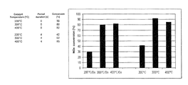
- the engine operating points were 1200 rpm/800 Nm, 1200 rpm/1200 Nm and 1200 rpm/1700 Nm; the resulting catalyst temperatures were 200° C., 300° C. and 400° C.
- FIG. 2 shows the NO x concentration (in ppm) was varied so as to give a periodic trapezoid curve, wherein the NO x concentration oscillated symmetrically about the NH 3 concentration of 1000 ppm between the limit values of 500 ppm and 1500 ppm; the period duration was four seconds.
- FIG. 3 shows the NO x conversion rates in % for the catalyst temperatures 200° C., 300° C. and 400° C. achieved under the conditions selected in FIG. 2 .
- FIG. 3 also shows the NO x conversion rates in % which were achieved with unvaried untreated NO x emissions, i.e. with period duration 0 seconds, and otherwise unchanged arrangement and procedure. It is not difficult to see that with the proposed method, a clear rise in NO x conversion rates is achieved even at low catalyst temperatures.
- the NO x concentration (in ppm) can naturally also be varied following another curve.
- a periodic rectangular curve is shown here, wherein the NO x concentration again oscillates symmetrically about the NH 3 concentration of 1000 ppm between the limit values 500 ppm and 1500 ppm.
- the period duration which in the example in FIG. 3 is two seconds, can be used as a parameter for optimising the NO x conversion rate.
- the feed ratio ⁇ need not necessarily oscillate symmetrically about the theoretical stationary value (solid line in FIG. 1 ); it can in practice prove more useful to select the falls and rises in untreated NO x emissions asymmetrically (dotted and dashed lines in FIG. 1 ).
- a generally valid variation of feed ratio ⁇ can only be specified in so far as the value a is varied positively and negatively about an assumed theoretical value and this variation must be achieved by brief rises and falls in the untreated NO x emissions.
- the optimum amount of rise and fall to a great extent depends on the catalyst materials used and must be determined empirically for a catalyst of a specific type.
- the core concept of the proposed process is that the NO 3 to NO x ratio (feed ratio ⁇ ) is varied by changing the untreated nitrous oxide emissions in phases such that the feed ratio ⁇ oscillates in phases about a theoretical stationary value.
- the operating conditions taken into account here can be the catalyst temperature and/or the ammonia charge level of the catalyst and/or the NO x conversion rate and/or the untreated NO x emissions and/or the NO 2 quantity upstream of the particle filter and/or the NO x emissions downstream of the exhaust gas post-treatment system and/or the NH 3 emissions downstream of the exhaust gas post-treatment system and/or the supplied quantity of reducing agent and/or the stored quantity of NH 3 and/or the NH 3 quantity which can be stored.
- Such operating conditions can be determined via sensors and/or via models, in the form of mathematical functions, maps and/or neuronal networks. Such techniques are well known to the person skilled in the art so no detailed description is required.
- the SCR catalyst allows unconsumed NH 3 to pass, it can be provided that this is decomposed by a charge of material with oxidative action arranged on the clean gas side and/or by increasing an ammonia storage capacity in the direction of the clean gas side to be able to buffer the ammonia peaks by storage.
Landscapes
- Engineering & Computer Science (AREA)
- Chemical & Material Sciences (AREA)
- Chemical Kinetics & Catalysis (AREA)
- Combustion & Propulsion (AREA)
- Mechanical Engineering (AREA)
- General Engineering & Computer Science (AREA)
- Health & Medical Sciences (AREA)
- Toxicology (AREA)
- Biomedical Technology (AREA)
- General Chemical & Material Sciences (AREA)
- Oil, Petroleum & Natural Gas (AREA)
- Analytical Chemistry (AREA)
- Environmental & Geological Engineering (AREA)
- Exhaust Gas After Treatment (AREA)
- Exhaust Gas Treatment By Means Of Catalyst (AREA)
Abstract
Description
(NH2)2CO→NH3+HNCO (1)
first thermolysis takes place, i.e., the chemical decomposition of urea. Then according to
HNCO+H2O→NH3+CO2 (2)
hydrolysis occurs, i.e., the catalytic decomposition of iscocyanic add (HNCO) into ammonia (NH3) and carbon dioxide (CO2).
4NO+4NH3+O2→4N2+6H2O (3)
α=NH3/NOx (4)
where: cNOx,0: untreated NOx emissions [ppm]
-
- cNOx: NOx emissions after catalyst [ppm]
|
where: A1, A2: educts
-
- A3, A4: products
- v1: stoichiometric factors
- v1<0 for educt
- v1>0 for product
then this proceeds at a specific speed known as the reaction speed “r” (7). This is defined as the temporal change in the component “i” in relation to the stoichiometric factor. It therefore relates to a reaction equation and is valueless without this being specified.
where: ni: mole count of component i [mol]
-
- t: time [s]
where: ci; concentration of component i [mol/m3]
r=k·c 1 m
where k: speed constant of reaction
-
- m: order of magnitude in relation to reactants Ai, miεR
- m:
total order of reaction
where kO: frequency or shock factor [mol1-m·s−1]
-
- EA: activation energy [J/mol]
- R: general gas constant 8.31 J/molK
R NO =k·c NO m ·c NH
wherein “m” normally assumes the value “one” and “n” the value “zero”.
2NO+O2
then the SCR reaction can be substantially accelerated and the low temperature activity perceptibly increased.
NO+2NH3+NO2→2N2+3H2O (15)
-
- advance of injection start,
- shift in the air/fuel ratio in the direction of higher lambda values,
- increase in injection pressure,
- reduction in the number of individual injections per working cycle,
- increase in intake air temperature, e.g., by bypassing the charge air cooler,
- reduction in the quantity of recirculated exhaust gas.
-
- cell count: 300 cpsi
- active component: V2O5 on WO3-stabilised TiO2
- volume: 30.3 l
Claims (13)
Applications Claiming Priority (3)
| Application Number | Priority Date | Filing Date | Title |
|---|---|---|---|
| DE102012006449 | 2012-03-30 | ||
| DE102012006449.7 | 2012-03-30 | ||
| DE102012006449A DE102012006449A1 (en) | 2012-03-30 | 2012-03-30 | Method of use in connection with an exhaust aftertreatment system |
Publications (2)
| Publication Number | Publication Date |
|---|---|
| US20130259778A1 US20130259778A1 (en) | 2013-10-03 |
| US8623306B2 true US8623306B2 (en) | 2014-01-07 |
Family
ID=47008249
Family Applications (1)
| Application Number | Title | Priority Date | Filing Date |
|---|---|---|---|
| US13/733,252 Active US8623306B2 (en) | 2012-03-30 | 2013-01-03 | Method for use in connection with an exhaust gas post-treatment system |
Country Status (6)
| Country | Link |
|---|---|
| US (1) | US8623306B2 (en) |
| EP (2) | EP2644859B1 (en) |
| CN (1) | CN103362612B (en) |
| BR (1) | BR102013007639B1 (en) |
| DE (1) | DE102012006449A1 (en) |
| RU (1) | RU2618758C2 (en) |
Families Citing this family (6)
| Publication number | Priority date | Publication date | Assignee | Title |
|---|---|---|---|---|
| JP6238807B2 (en) * | 2014-03-25 | 2017-11-29 | 日立オートモティブシステムズ株式会社 | Engine control device |
| JP6733652B2 (en) * | 2017-12-27 | 2020-08-05 | トヨタ自動車株式会社 | Exhaust gas purification device for internal combustion engine |
| JP6733651B2 (en) | 2017-12-27 | 2020-08-05 | トヨタ自動車株式会社 | Exhaust gas purification device for internal combustion engine |
| JP6729543B2 (en) | 2017-12-27 | 2020-07-22 | トヨタ自動車株式会社 | Exhaust gas purification device for internal combustion engine |
| AT521760B1 (en) * | 2018-10-11 | 2021-03-15 | Avl List Gmbh | Frequency-based NH3 slip detection method |
| CN120487400B (en) * | 2025-07-17 | 2025-09-19 | 潍柴动力股份有限公司 | Methanol engine protection method, electronic control unit and vehicle |
Citations (6)
| Publication number | Priority date | Publication date | Assignee | Title |
|---|---|---|---|---|
| DE3604045C1 (en) | 1986-02-08 | 1987-01-29 | Steag Ag | Process for the separation of nitrogen oxides from flue gases |
| EP0362483A1 (en) | 1988-07-25 | 1990-04-11 | Degussa Aktiengesellschaft | Process for catalytic removal of nitrogen oxides from waste gases by a reducing agent |
| DE4038054A1 (en) | 1990-11-29 | 1992-06-04 | Man Technologie Gmbh | METHOD AND DEVICE FOR SELECTIVE CATALYTIC NO (DOWN ARROW) X (DOWN ARROW) REDUCTION IN OXYGEN-BASED EXHAUST GASES |
| US5185305A (en) * | 1991-11-08 | 1993-02-09 | Ford Motor Company | Catalyst system for treating the exhaust from a lean-burn gasoline-fueled engine |
| US20080250778A1 (en) * | 2007-04-10 | 2008-10-16 | Solbrig Charles E | Excess NH3 storage control for SCR catalysts |
| US20120006004A1 (en) * | 2010-07-12 | 2012-01-12 | Mack Trucks, Inc. | Methods and systems for controlling reductant levels in an scr catalyst |
Family Cites Families (11)
| Publication number | Priority date | Publication date | Assignee | Title |
|---|---|---|---|---|
| GB9802504D0 (en) * | 1998-02-06 | 1998-04-01 | Johnson Matthey Plc | Improvements in emission control |
| JP3873904B2 (en) * | 2003-02-26 | 2007-01-31 | 日産自動車株式会社 | Exhaust gas purification device for internal combustion engine |
| DE102006021089B4 (en) * | 2006-05-05 | 2009-11-12 | Continental Automotive Gmbh | Method and device for operating an internal combustion engine |
| RU2423614C2 (en) * | 2006-06-14 | 2011-07-10 | Вольво Ластвагнар Аб | Procedure and system for regeneration of device for purification of burnt gases |
| US8041498B2 (en) * | 2008-08-29 | 2011-10-18 | GM Global Technology Operations LLC | Lean nitrogen oxide emission control system and method |
| DE102008048518A1 (en) * | 2008-09-23 | 2010-03-25 | Man Nutzfahrzeuge Ag | Device for cleaning an exhaust gas stream of an internal combustion engine of a motor vehicle, in particular of a commercial vehicle |
| DE102009012093A1 (en) * | 2009-03-06 | 2010-09-09 | Man Nutzfahrzeuge Ag | Method for adjusting the dosages of the reducing agent with selective catalytic reduction |
| CN102549245B (en) * | 2009-06-03 | 2014-06-11 | 丰田自动车株式会社 | Exhaust gas purification device for internal combustion engine |
| US20110047970A1 (en) * | 2009-09-01 | 2011-03-03 | Cummins Intellectual Properties, Inc. | HIGH EFFICIENCY NOx REDUCTION SYSTEM AND METHOD |
| JP5146545B2 (en) * | 2009-11-12 | 2013-02-20 | トヨタ自動車株式会社 | Exhaust gas purification system for internal combustion engine |
| US8640448B2 (en) * | 2010-05-03 | 2014-02-04 | Cummins Inc. | Transient compensation control of an SCR aftertreatment system |
-
2012
- 2012-03-30 DE DE102012006449A patent/DE102012006449A1/en active Pending
- 2012-09-27 EP EP12006739.2A patent/EP2644859B1/en active Active
- 2012-09-27 EP EP21192498.0A patent/EP3929414B1/en active Active
-
2013
- 2013-01-03 US US13/733,252 patent/US8623306B2/en active Active
- 2013-03-14 RU RU2013111503A patent/RU2618758C2/en active
- 2013-03-28 CN CN201310104182.2A patent/CN103362612B/en active Active
- 2013-03-28 BR BR102013007639-2A patent/BR102013007639B1/en active IP Right Grant
Patent Citations (6)
| Publication number | Priority date | Publication date | Assignee | Title |
|---|---|---|---|---|
| DE3604045C1 (en) | 1986-02-08 | 1987-01-29 | Steag Ag | Process for the separation of nitrogen oxides from flue gases |
| EP0362483A1 (en) | 1988-07-25 | 1990-04-11 | Degussa Aktiengesellschaft | Process for catalytic removal of nitrogen oxides from waste gases by a reducing agent |
| DE4038054A1 (en) | 1990-11-29 | 1992-06-04 | Man Technologie Gmbh | METHOD AND DEVICE FOR SELECTIVE CATALYTIC NO (DOWN ARROW) X (DOWN ARROW) REDUCTION IN OXYGEN-BASED EXHAUST GASES |
| US5185305A (en) * | 1991-11-08 | 1993-02-09 | Ford Motor Company | Catalyst system for treating the exhaust from a lean-burn gasoline-fueled engine |
| US20080250778A1 (en) * | 2007-04-10 | 2008-10-16 | Solbrig Charles E | Excess NH3 storage control for SCR catalysts |
| US20120006004A1 (en) * | 2010-07-12 | 2012-01-12 | Mack Trucks, Inc. | Methods and systems for controlling reductant levels in an scr catalyst |
Also Published As
| Publication number | Publication date |
|---|---|
| DE102012006449A1 (en) | 2013-10-02 |
| EP2644859A3 (en) | 2014-11-12 |
| RU2013111503A (en) | 2014-09-20 |
| EP3929414A1 (en) | 2021-12-29 |
| BR102013007639B1 (en) | 2024-03-05 |
| CN103362612A (en) | 2013-10-23 |
| RU2618758C2 (en) | 2017-05-11 |
| CN103362612B (en) | 2017-05-31 |
| EP3929414B1 (en) | 2026-04-22 |
| BR102013007639A2 (en) | 2015-07-07 |
| EP2644859B1 (en) | 2021-09-15 |
| EP2644859A2 (en) | 2013-10-02 |
| US20130259778A1 (en) | 2013-10-03 |
Similar Documents
| Publication | Publication Date | Title |
|---|---|---|
| US8623306B2 (en) | Method for use in connection with an exhaust gas post-treatment system | |
| US7861516B2 (en) | Methods of controlling reductant addition | |
| CN101979847B (en) | Exhaust gas treatment system including HC-SCR and two-way catalyst and method of using same | |
| US8333062B2 (en) | Method for monitoring ammonia storage in an exhaust aftertreatment system | |
| CN101285412B (en) | Storage control method and system for excess NH3 in SCR catalyst | |
| US8555617B2 (en) | Exhaust gas treatment system including a four-way catalyst and urea SCR catalyst and method of using the same | |
| US8635855B2 (en) | Exhaust gas treatment system including a lean NOx trap and two-way catalyst and method of using the same | |
| EP2543837B1 (en) | Exhaust gas purification apparatus of an internal combustion engine | |
| CN109281737B (en) | Method of controlling and monitoring oxidation catalyst device | |
| US8505279B2 (en) | Exhaust gas treatment system including a four-way catalyst and urea SCR catalyst and method of using the same | |
| US9381466B2 (en) | Exhaust gas purification system | |
| US20040098973A1 (en) | Exhaust gas aftertreatment systems | |
| US20040098979A1 (en) | Exhaust gas aftertreatment systems | |
| US8869515B2 (en) | Method for controlling pollutant emissions from a combustion engine | |
| US20100122520A1 (en) | System for Controlling Urea Injection Quantity of Vehicle and Method Thereof | |
| BRPI0804720B1 (en) | METHOD FOR IMPROVING HYDROLYSIS OF A REDUCING AGENT IN AN EXHAUST GAS HANDLING AND ARRANGEMENT SYSTEM TO PERFORM THE METHOD TO IMPROVE HYDROLYSIS | |
| CN104847459A (en) | Internal combustion engine | |
| US9051865B2 (en) | Method for controlling a system for the treatment of exhaust gases from an internal combustion engine | |
| US10774715B1 (en) | Stabilization of aqueous urea solutions containing organometallic catalyst precursors | |
| Kurien et al. | Solid reductant based selective catalytic reduction system for exhaust emission control of compression ignition engines | |
| US11391190B2 (en) | Combined catalyst precursor/surfactant mixture for reductant urea solution for selective catalytic reduction | |
| JP2011226402A (en) | Exhaust emission control device | |
| EP4192616B1 (en) | Stabilization of aqueous urea solutions containing organometallic catalyst precursors | |
| JP4720773B2 (en) | Exhaust gas purification device for internal combustion engine |
Legal Events
| Date | Code | Title | Description |
|---|---|---|---|
| AS | Assignment |
Owner name: MAN TRUCK & BUS AG, GERMANY Free format text: ASSIGNMENT OF ASSIGNORS INTEREST;ASSIGNOR:DOERING, ANDREAS;REEL/FRAME:029559/0720 Effective date: 20121219 |
|
| STCF | Information on status: patent grant |
Free format text: PATENTED CASE |
|
| FPAY | Fee payment |
Year of fee payment: 4 |
|
| AS | Assignment |
Owner name: MAN TRUCK & BUS SE, GERMANY Free format text: CHANGE OF NAME;ASSIGNOR:MAN TRUCK & BUS AG;REEL/FRAME:052119/0144 Effective date: 20190225 |
|
| MAFP | Maintenance fee payment |
Free format text: PAYMENT OF MAINTENANCE FEE, 8TH YEAR, LARGE ENTITY (ORIGINAL EVENT CODE: M1552); ENTITY STATUS OF PATENT OWNER: LARGE ENTITY Year of fee payment: 8 |
|
| MAFP | Maintenance fee payment |
Free format text: PAYMENT OF MAINTENANCE FEE, 12TH YEAR, LARGE ENTITY (ORIGINAL EVENT CODE: M1553); ENTITY STATUS OF PATENT OWNER: LARGE ENTITY Year of fee payment: 12 |