US8622758B2 - Rotatable plug and power supply device having the rotatable plug - Google Patents
Rotatable plug and power supply device having the rotatable plug Download PDFInfo
- Publication number
- US8622758B2 US8622758B2 US13/556,362 US201213556362A US8622758B2 US 8622758 B2 US8622758 B2 US 8622758B2 US 201213556362 A US201213556362 A US 201213556362A US 8622758 B2 US8622758 B2 US 8622758B2
- Authority
- US
- United States
- Prior art keywords
- conductive
- rotatable
- unit
- pair
- casing part
- Prior art date
- Legal status (The legal status is an assumption and is not a legal conclusion. Google has not performed a legal analysis and makes no representation as to the accuracy of the status listed.)
- Active
Links
Images


Classifications
-
- H—ELECTRICITY
- H01—ELECTRIC ELEMENTS
- H01R—ELECTRICALLY-CONDUCTIVE CONNECTIONS; STRUCTURAL ASSOCIATIONS OF A PLURALITY OF MUTUALLY-INSULATED ELECTRICAL CONNECTING ELEMENTS; COUPLING DEVICES; CURRENT COLLECTORS
- H01R31/00—Coupling parts supported only by co-operation with counterpart
- H01R31/06—Intermediate parts for linking two coupling parts, e.g. adapter
- H01R31/065—Intermediate parts for linking two coupling parts, e.g. adapter with built-in electric apparatus
-
- H—ELECTRICITY
- H01—ELECTRIC ELEMENTS
- H01R—ELECTRICALLY-CONDUCTIVE CONNECTIONS; STRUCTURAL ASSOCIATIONS OF A PLURALITY OF MUTUALLY-INSULATED ELECTRICAL CONNECTING ELEMENTS; COUPLING DEVICES; CURRENT COLLECTORS
- H01R13/00—Details of coupling devices of the kinds covered by groups H01R12/70 or H01R24/00 - H01R33/00
- H01R13/66—Structural association with built-in electrical component
- H01R13/70—Structural association with built-in electrical component with built-in switch
- H01R13/71—Contact members of coupling parts operating as switch, e.g. linear or rotational movement required after mechanical engagement of coupling part to establish electrical connection
Definitions
- the invention relates to a rotatable plug, more particularly to a rotatable plug that can be stored conveniently when not in use and a power supply device having the rotatable plug.
- a plug of a conventional power supply device includes a plug body and two conductive terminals protruding outwardly from the plug body.
- the conductive terminals protrude from the plug body, they are likely to be hit by an external force that may result in the bending and even breakage thereof. Further, it is difficult to store the conventional power supply device. Therefore, devices with rotatable plugs have been currently developed to resolve the aforesaid issues.
- a conventional power supply device having a rotatable plug includes a housing 11 , a rotatable plug 12 and a fixing element 13 .
- the housing 11 includes a housing body 111 , a holding seat 112 formed on an end of the housing body 111 , and a receiving hole 113 extending through the holding seat 112 .
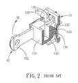
- the rotatable plug 12 includes a rotating support body 121 inserted into the receiving hole 113 , two conductive prongs 122 fixed on the rotating support body 121 , two metal pivot studs 123 protruding outwardly and respectively from two opposite ends of the rotating support body 121 , two conductive plates 124 respectively pivoted to the pivot studs 123 , and three projections 125 , 126 projecting from the rotating support body 121 opposite to the conductive prongs 122 .
- Two conductive wires may be respectively inserted through the conductive plates 124 to connect electrically with a circuit board (not shown).
- the fixing element 13 fixes the rotatable plug 12 to the holding seat 112 , and includes a fixing main body 131 , two stop bosses 132 disposed on one side of the fixing main body 131 and extending towards the housing body 111 , a stepped portion formed in the middle of the fixing main body 131 and having a first part 133 and a second part 134 , and two spaced-apart slots 135 formed in the fixing main body 131 .
- the conductive plates 124 extend respectively through the slots 135 .
- the housing 11 (see FIG. 1 ) is removed in FIGS. 2 and 3 to facilitate description of the rotating mechanism of the rotatable plug 12 .
- the projection 125 abuts against the first and second parts 133 , 134 of the stepped portion and is positioned thereat.
- the projection 125 can slide over the second part 134 .
- the conductive prongs 122 can drive the rotating support body 121 to rotate relative to the holding seat (see FIG.
- the above-mentioned device is not modular so that a new mold must be opened in respond to different sizes of housing 11 .
- three projections 125 , 126 are needed to position the rotatable plug 12 in the use and non-use positions.
- the rotatable plug 12 is connected to the fixing element 13 through insertion of the conductive plates 124 into the slots 135 , the conductive plates 124 are likely to separate from the fixing element 13 due to frequent use which may cause poor electrical contact.
- an object of the present invention is to provide a rotatable plug that can provide a stable and reliable electrical connection.
- Another object of the present invention is to provide a power supply device having a rotatable plug that can provide a stable and reliable electrical connection.
- a rotatable plug comprises a casing unit, a pair of conductive terminals and a rotatable unit.
- the casing unit includes a first casing part, and a second casing part connected to the first casing part and formed with a pair of receiving spaces.
- the conductive terminals are insert molded into the first casing part.
- Each of the conductive terminals has a conductive section.
- the rotatable unit includes a pivot shaft, a pair of conductive prongs connected to and extending transversely from the pivot shaft, and a pair of conductive protrusions protruding out from the pivot shaft.
- the rotatable unit is disposed in the casing unit and is rotatable relative to the casing unit between a non-use and folded position, where the conductive prongs are respectively accommodated in the receiving spaces, and a use or extended position, where the conductive prongs respectively extend out of the receiving spaces.
- Each of the conductive protrusions is disposed on and has at least two points of contact with the conductive section of a respective one of the conductive terminals when the rotatable unit is in the use position.
- the conductive section of each of the conductive terminals has a depressed contact surface.
- Each of the conductive protrusions has the at least two points of contact with the depressed contact surface.
- the first casing part includes a pair of first support posts each having a slotted surface.
- Each of the conductive terminals further has a conductive end protruding from the slotted surface.
- the pivot shaft includes two outer conductive shaft sections respectively connected to the prongs, and an insulated middle shaft section between the outer conductive shaft sections. The outer conductive shaft sections are respectively in contact with the conductive ends of the conductive terminals when the rotatable unit is in the use and non-use positions.
- the first casing part includes a pair of second support posts supporting the pivot shaft.
- the first casing part has a positioning portion formed with a positioning groove.
- the rotatable unit further includes a first protuberance and a second protuberance protruding from the pivot shaft between the conductive protrusions and perpendicular to each other.
- the first protuberance is positioned in the positioning groove when in the non-use position, and the second protuberance is positioned in the positioning groove when in the use position.
- each of the conductive terminals further has a conductive extension disposed externally of the casing unit.
- the conductive extensions of the conductive terminals have different lengths.
- a power supply device comprises a housing unit, a circuit unit and a rotatable plug.
- the housing unit includes a first housing element having two parallel slots, and a second housing element connected to and cooperating with the first housing element to define a chamber.
- the circuit unit is disposed in the chamber.
- the rotatable plug is disposed in the chamber and includes a casing unit, a pair of conductive terminals and a rotatable unit.
- the casing unit includes a first casing part, and a second casing part connected to the first casing part and formed with a pair of receiving spaces.
- the conductive terminals are insert molded into the first casing part and are connected electrically to the circuit unit.
- Each of the conductive terminals has a conductive section.
- the rotatable unit includes a pivot shaft, a pair of conductive prongs connected transversely to the pivot shaft, and a pair of conductive protrusions protruding out from the pivot shaft.
- the rotatable unit is disposed in the casing unit and is rotatable relative to the casing unit between a non-use or folded position, where the conductive prongs are respectively accommodated in the receiving spaces and the slots, and a use or extended position, where the conductive prongs respectively extend out of the receiving spaces and the slots.
- Each of the conductive protrusions is disposed on and has at least two points of contact with the conductive section of a respective one of the conductive terminals when the rotatable unit is in the use position.
- each of the receiving spaces includes a cover-receiving section, and a prong-receiving section communicating spatially with said cover-receiving section.
- Each of the slots has a length greater than or equal to a length of a corresponding receiving space and a width greater than or equal to a width of a corresponding prong-receiving section.
- each arcuate conductive protrusion has at least two points of contact with the depressed contact surface of the corresponding conductive section
- the rotatable plug of the present invention has a good effect of conduction.
- the conductive terminals are insert molded into the first casing part so that only the conductive sections and the conductive ends thereof protrude inwardly from the inner surface of the first casing part, the fixing method thereof is stable and the electrical connection process thereof is reliable.
- FIG. 1 is an exploded perspective view of a conventional power supply device having a rotatable plug
- FIG. 2 is a fragmentary perspective view of the conventional power supply device, illustrating a conductive prong in a use position
- FIG. 3 is a view similar to FIG. 2 , but illustrating the conductive prong in a non-use position
- FIG. 4 is an exploded perspective view of a power supply device having a rotatable plug according to the preferred embodiment of the present invention
- FIG. 5 is a perspective view of a first casing part of the rotatable plug
- FIG. 6 is a perspective view of a pair of conductive terminals of the rotatable plug
- FIG. 7 is a perspective view of a second casing part of the rotatable plug
- FIG. 8 is a perspective view of a rotatable unit of the rotatable plug
- FIG. 9 is a perspective view of a pair of conductive prongs of the rotatable plug.
- FIG. 10 is an assembled perspective view of the rotatable plug in a non-use position
- FIG. 11 is a perspective view of the rotatable plug in the non-use position with the second casing part thereof removed for clarity's sake;
- FIG. 12 is a view similar to FIG. 10 , but with the rotatable plug in a use position;
- FIG. 13 is a perspective view of the rotatable plug in the use position with the second casing part thereof removed for clarity's sake;
- FIG. 14 is a schematic top view of the rotatable plug in the use position with the second casing part thereof removed;
- FIG. 15 is a sectional view of the rotatable plug taken along line A-A of FIG. 14 ;
- FIG. 16 is a view similar to FIG. 15 , but showing a conductive protrusion in two points of contact with a V-shaped conductive section;
- FIG. 17 is a sectional view of the rotatable plug taken along line B-B of FIG. 14 ;
- FIG. 18 is a perspective view of the power supply device with a second housing element thereof being removed to illustrate how the rotatable plug is disposed in a first housing element thereof;
- FIG. 19 is a view similar to FIG. 18 , but with the conductive prongs of the rotatable plug being rotated from the non-use position to the use position;
- FIG. 20 is a view similar to FIG. 19 , but with the second housing element of the power supply device being coupled to the first housing element thereof.
- a power supply device comprises a housing unit 5 , a circuit unit, and a rotatable plug 200 .
- the housing unit 5 includes a first housing element 51 and a second housing element 52 connected to and cooperating with the first housing element 51 to define a chamber 53 (see FIG. 18 ).
- the first housing element 51 has a base wall 511 , a surrounding wall 512 extending transversely from the base wall 511 , and two parallel slots 513 formed in the surrounding wall 512 .
- the circuit unit 6 and the rotatable plug 200 are disposed in the chamber 53 .
- the rotatable plug 200 includes a casing unit 2 , a pair of conductive terminals 3 and a rotatable unit 4 .
- the casing unit 2 includes a first casing part 21 and a second casing part 22 connected to the first casing part 21 .
- the first casing part 21 includes a plate-shaped body 211 , a pair of first support posts 212 extending inwardly and respectively from two opposite sides of the plate-shaped body 211 , a pair of second support posts 213 disposed between the first support posts 212 , and a positioning portion 214 extending inwardly from the plate-shaped body 211 and disposed between the second support posts 213 .
- each first support post 212 is hollow, extends from an inner surface of the plate-shaped body 211 at the two opposite sides thereof, and has an arcuate slotted surface 216 distal from the plate-shaped body 211 .
- the positioning portion 214 is formed with a central positioning groove 217 .
- the conductive terminals 3 are insert molded into the first casing part 21 and are connected electrically to the circuit unit 6 .
- Each of the conductive terminals 3 has a conductive section 31 disposed between one of the first support posts 212 and a corresponding second support post 213 , a conductive end 32 protruding from the slotted surface 216 of a respective first support post 212 , and a conductive extension 33 opposite to the conductive end 32 and extending from an outer surface of the plate-shaped body 211 .
- the conductive section 31 has a depressed contact surface 311 .
- the conductive end 32 is arcuate.
- each conductive terminal 3 before being insert molded into the first casing part 21 is as shown in FIG. 6 .
- the conductive section 31 of each conductive terminal 3 is substantially U-shaped, and includes a bight portion having the depressed contact surface 311 , and two arms extending transversely from two opposite ends of the bight portion.
- Each conductive terminal 3 further has a first conductive plate 34 and a second conductive plate 35 respectively connected to and extending horizontally from the two opposite arms of the conductive section 31 , and a third conductive plate 36 that is substantially J-shaped and that has one end connected to the bight portion and another end having the arcuate conductive end 32 .
- the conductive extension 33 extends from one end of the first conductive plate 34 that is distal from the conductive section 31 . To easily distinguish the positive and negative polarities of the conductive terminals 3 , the two conductive extensions 33 have different lengths.
- the conductive extension 33 has a through hole 37 . Two conductive wires (not shown) can be soldered to the through holes 37 in the conductive extensions 33 of the conductive terminals 3 to connect electrically with the conductive extensions 33 .
- the second casing part 22 includes a casing body 221 , and a pair of parallel receiving spaces 222 formed in the casing body 221 .
- Each of the receiving spaces 222 includes a cover-receiving section 223 , and a prong-receiving section 224 communicating spatially with the cover-receiving section 223 .
- the rotatable unit 4 includes a pivot shaft 41 , and a pair of parallel conductive prongs 42 connected transversely to the pivot shaft 41 .
- the pivot shaft 41 includes two outer conductive shaft sections 43 respectively connected to the prongs 42 , an insulated middle shaft section 411 between the outer conductive shaft sections 43 , and two cover sections 412 disposed respectively on two opposite ends of the middle shaft section 411 .
- Each of the cover sections 412 covers a junction of the outer conductive shaft sections 43 and a respective prong 42 .
- a first protuberance 45 and a second protuberance 46 protrude outwardly from the middle shaft section 411 , are perpendicular to each other, and are made of insulated materials.
- a pair of conductive protrusions 44 respectively protrudes out from the cover sections 412 of the pivot shaft 41 .
- the rotatable unit 4 has the prongs 42 , which are made of metal, insert molded to the pivot shaft 41 such that the cover sections 412 of the pivot shaft 41 cover partially the prongs 42 .
- the configuration thereof is as shown in FIG. 9 .
- Each of the prongs 42 includes an elongated insert section 421 , and a connecting section 422 opposite to the insert section 421 .
- the conductive protrusions 44 protrude outwardly and respectively from the connecting sections 422 of the prongs 42 , and are disposed externally of the cover sections 412 , respectively.
- the rotatable unit 4 is first connected to the second casing part 22 by inserting the cover sections 412 of the pivot shaft 41 into the corresponding cover-receiving sections 223 of the receiving spaces 222 and the prongs 42 into the corresponding prong-receiving sections 224 of the receiving spaces 222 .
- a portion of the insert section 421 of each prong 42 extends out of the corresponding prong-receiving section 224 , and the outer conductive shaft sections 43 are exposed from lateral sides of the casing body 221 (only one is visible in FIG. 10 ).
- the second casing part 22 and the rotatable unit 4 are then integrated with the first casing part 21 such that the middle shaft section 411 of the pivot shaft 41 abuts against the second support posts 213 and the outer conductive shaft sections 43 abut against and electrically coupled to the conductive ends 32 of the conductive terminals 3 .
- the first casing part 21 further includes a plurality of welding spots 218 arranged on a periphery of the inner surface of the plate-shaped body 211 , the first and second casing parts 21 , 22 are integrated together using an ultrasonic welding process.
- the rotatable unit 4 is disposed in the casing unit 2 and is rotatable relative to the same between a non-use or folded position and a use or extended position.
- the second casing part 22 is removed in FIGS. 11 and 13 to facilitate description of the positioning mechanism of the rotatable unit 4 during the non-use and use positions.
- the insert sections 421 of the prongs 42 are respectively accommodated in the prong-receiving sections 224 with the portions thereof protruding from the corresponding prong-receiving sections 224 , and the first protuberance 45 is positioned in the positioning groove 217 (see FIG. 5 ).
- the insert sections 421 of the prongs 42 are rotated in the direction of an arrow (I) to extend out of the prong-receiving sections 224 , the second protuberance 46 is positioned in the positioning groove 217 , as shown in FIGS. 12 to 14 . As shown in FIG.
- the conductive protrusion 44 is disposed on the conductive section 31 . Since the conductive section 31 has the depressed contact surface 311 and the conductive protrusion 44 is arcuate, the conductive protrusion 44 has at least two points of contact with the conductive section 31 so that it has a large area of contact with the same to thereby enhance the effect of conduction.
- the conductive section 31 is not limited to having the depressed contact surface 311 . As shown in FIG. 16 , the conductive section 31 may have a substantially V-shaped contact surface 311 ′, so that the conductive protrusion 44 has two points of contact with the conductive section 31 . As shown in FIG. 12 , when the insert sections 421 of the prongs 42 are rotated in the direction of an arrow (II), the rotatable unit 4 is rotated back to the non-use position shown in FIGS. 10 and 11 .
- the outer conductive shaft section 43 is in constant contact with the conductive end 32 whether the rotatable unit 4 is in the non-use or use position.
- the conductive terminals 3 and the rotatable unit 4 are electrically coupled to each other through the aforesaid two methods, so that reliability of electrical connection can be enhanced. Further, referring once again to FIGS.
- the cover-receiving section 223 of each receiving space 222 has a width (W 1 )
- the prong-receiving section 224 of each receiving space 222 has a width (W 2 )
- each cover section 412 of the pivot shaft 41 has a thickness (T 1 )
- each prong 42 has a thickness (T 2 ).
- the insert sections 421 of the prongs 42 can be stably received in the prong-receiving sections 224 of the second casing part 22 .
- the conductive sections 31 have elasticity, when the conductive sections 31 are in contact with or separated from the conductive protrusions 44 , the wearing thereof caused by repeated rotation between the non-use and use positions can be reduced. Further, by using the ultrasonic welding method to integrate the first and second casing parts 21 , 22 , the separation of the first and second casing parts 21 , 22 due to the frequent switching between the non-use and use positions can be prevented.
- each of the slots 513 in the housing unit 5 has a length slightly longer than or equal to that of the corresponding receiving space 222 , and a width larger than or equal to that of the corresponding prong-receiving section 224 .
- the outer surface of the casing body 221 of the second casing part 22 abuts against inner surfaces of the base wall 511 and the surrounding wall 512 and is proximate to the two slots 513 , so that the cover-receiving sections 223 and the prong-receiving sections 224 of the receiving spaces 222 are in spatial communication with the slots 513 to facilitate rotation of the insert sections 421 of the prongs 42 in and out of the housing unit 5 .
- the rotatable unit 4 is similarly rotatable relative to the casing unit 2 between the non-use or folded position and the use or extended position as described above.
- the difference resides in that the insert sections 421 of the prongs 42 of the rotatable unit 4 can be rotatably received in the respective slots 513 of the first housing element 51 .
- the insert sections 421 of the prongs 42 are accommodated in the slots 513 .
- the insert sections 421 are rotated in the direction of the arrow (I), as shown in FIGS. 19 and 20 , the insert sections 421 are moved to extend out of the respective slots 513 .
- the insert sections 421 are rotated in the direction of the arrow (II)
- the insert sections 421 are moved back to the position shown in FIG. 18 .
- each arcuate conductive protrusion 44 has at least two points of contact with the depressed contact surface 311 of the corresponding conductive section 31 , the rotatable plug of the present invention has a good effect of conduction.
- the conductive terminals 3 are insert molded into the first casing part 21 so that only the conductive sections 31 and the conductive ends 32 thereof protrude inwardly from the inner surface of the first casing part 21 , the fixing method thereof is stable and the electrical connection thereof is reliable.
- the present invention can be modular. Hence, the objects of the present invention can be realized.
Landscapes
- Connector Housings Or Holding Contact Members (AREA)
- Details Of Connecting Devices For Male And Female Coupling (AREA)
Abstract
Description
Claims (15)
Applications Claiming Priority (3)
| Application Number | Priority Date | Filing Date | Title |
|---|---|---|---|
| CN2012200832235U CN202662950U (en) | 2012-03-07 | 2012-03-07 | Rotary plug and power supply device with rotary plug |
| CN201220083223.5 | 2012-03-07 | ||
| CN201220083223U | 2012-03-07 |
Publications (2)
| Publication Number | Publication Date |
|---|---|
| US20130237073A1 US20130237073A1 (en) | 2013-09-12 |
| US8622758B2 true US8622758B2 (en) | 2014-01-07 |
Family
ID=47457829
Family Applications (1)
| Application Number | Title | Priority Date | Filing Date |
|---|---|---|---|
| US13/556,362 Active US8622758B2 (en) | 2012-03-07 | 2012-07-24 | Rotatable plug and power supply device having the rotatable plug |
Country Status (2)
| Country | Link |
|---|---|
| US (1) | US8622758B2 (en) |
| CN (1) | CN202662950U (en) |
Cited By (3)
| Publication number | Priority date | Publication date | Assignee | Title |
|---|---|---|---|---|
| US20150118873A1 (en) * | 2013-10-29 | 2015-04-30 | Velvetwire Llc | Plug-in device having a foldable plug |
| US9077093B1 (en) * | 2014-04-23 | 2015-07-07 | Apple Inc. | Magnetic rotation actuator |
| US20250158322A1 (en) * | 2023-11-09 | 2025-05-15 | Chicony Power Technology Co., Ltd. | Rotatable terminal module |
Families Citing this family (4)
| Publication number | Priority date | Publication date | Assignee | Title |
|---|---|---|---|---|
| CN109411939B (en) * | 2017-08-16 | 2020-09-11 | 康塔克整合解决股份有限公司 | Plug device |
| CN107517555B (en) * | 2017-09-11 | 2024-09-03 | 深圳传音制造有限公司 | Housing and mobile terminal |
| CN116176312B (en) * | 2021-11-26 | 2024-10-11 | 比亚迪股份有限公司 | Contactor and charging and distribution system, charging pile, and vehicle having the same |
| CN222530864U (en) * | 2024-03-12 | 2025-02-25 | 安克创新科技股份有限公司 | A plug |
Citations (4)
| Publication number | Priority date | Publication date | Assignee | Title |
|---|---|---|---|---|
| US5494449A (en) * | 1994-09-01 | 1996-02-27 | Chioo; Ming D. | Power supply device for portable computers |
| US5628641A (en) * | 1994-02-24 | 1997-05-13 | Asian Micro Sources, Inc. | Collapsible plug device for battery charger |
| US6275002B1 (en) * | 2001-01-23 | 2001-08-14 | Son Kon Co., Ltd. | Rotary charging plug structure of a charger |
| US7001196B1 (en) * | 2005-03-07 | 2006-02-21 | Cheng Uei Precision Industry Co., Ltd. | Rotatable plug with an arcing resistant mechanism |
-
2012
- 2012-03-07 CN CN2012200832235U patent/CN202662950U/en not_active Expired - Fee Related
- 2012-07-24 US US13/556,362 patent/US8622758B2/en active Active
Patent Citations (4)
| Publication number | Priority date | Publication date | Assignee | Title |
|---|---|---|---|---|
| US5628641A (en) * | 1994-02-24 | 1997-05-13 | Asian Micro Sources, Inc. | Collapsible plug device for battery charger |
| US5494449A (en) * | 1994-09-01 | 1996-02-27 | Chioo; Ming D. | Power supply device for portable computers |
| US6275002B1 (en) * | 2001-01-23 | 2001-08-14 | Son Kon Co., Ltd. | Rotary charging plug structure of a charger |
| US7001196B1 (en) * | 2005-03-07 | 2006-02-21 | Cheng Uei Precision Industry Co., Ltd. | Rotatable plug with an arcing resistant mechanism |
Cited By (4)
| Publication number | Priority date | Publication date | Assignee | Title |
|---|---|---|---|---|
| US20150118873A1 (en) * | 2013-10-29 | 2015-04-30 | Velvetwire Llc | Plug-in device having a foldable plug |
| US9270066B2 (en) * | 2013-10-29 | 2016-02-23 | Velvetwire Llc | Plug-in device having a plug with blades and a pivot with a locking cam and a bending cam |
| US9077093B1 (en) * | 2014-04-23 | 2015-07-07 | Apple Inc. | Magnetic rotation actuator |
| US20250158322A1 (en) * | 2023-11-09 | 2025-05-15 | Chicony Power Technology Co., Ltd. | Rotatable terminal module |
Also Published As
| Publication number | Publication date |
|---|---|
| CN202662950U (en) | 2013-01-09 |
| US20130237073A1 (en) | 2013-09-12 |
Similar Documents
| Publication | Publication Date | Title |
|---|---|---|
| US8622758B2 (en) | Rotatable plug and power supply device having the rotatable plug | |
| US10243296B2 (en) | Safety socket with means to prevent electric shock and electrical discharge | |
| US7914307B1 (en) | Socket with movable lids for shielding plug holes | |
| US20180358729A1 (en) | Electrical connector having interconnected power contact and adjacent holding member | |
| JP5492882B2 (en) | Adapter plug | |
| US7381059B2 (en) | Power supply device with rotatable plug | |
| JP5389957B2 (en) | High current electrical connector | |
| US20130316553A1 (en) | Electric connector with plug module | |
| US10985490B1 (en) | Safety socket | |
| US6991482B1 (en) | Power plug | |
| US20080064248A1 (en) | Firm-structured plug | |
| JP2017212190A (en) | Rotating mechanism and adapter having the rotating mechanism | |
| US7104813B1 (en) | Power plug structure | |
| JP2004152594A (en) | Electric terminal | |
| TWM507075U (en) | Battery connector | |
| US5854456A (en) | Line switch having a parallel arrangement between conducting plates with piercing tips and the electrical cord | |
| JP2001167849A (en) | Electric connector | |
| EP2897228A1 (en) | Terminal device and electric outlet using same | |
| US4725245A (en) | Electric outlet assembly | |
| US7189095B1 (en) | Lamp socket for two different types of lamps | |
| JP3736621B2 (en) | Jack structure | |
| CN204088712U (en) | Connector and electronic device with connector | |
| KR100389420B1 (en) | Lamp mounting device for microwave oven | |
| CN208157701U (en) | Socket connector | |
| JP6621023B2 (en) | Table tap and table tap manufacturing method |
Legal Events
| Date | Code | Title | Description |
|---|---|---|---|
| AS | Assignment |
Owner name: SILITEK ELECTRONICS (GUANGZHOU) CO., LTD., CHINA Free format text: ASSIGNMENT OF ASSIGNORS INTEREST;ASSIGNORS:HSU, CHIA-TSANG;CHU, CHIEN-HUA;REEL/FRAME:028632/0715 Effective date: 20120717 Owner name: LITE-ON TECHNOLOGY CORP., TAIWAN Free format text: ASSIGNMENT OF ASSIGNORS INTEREST;ASSIGNORS:HSU, CHIA-TSANG;CHU, CHIEN-HUA;REEL/FRAME:028632/0715 Effective date: 20120717 |
|
| AS | Assignment |
Owner name: LITE-ON ELECTRONICS (GUANGZHOU) LIMITED, CHINA Free format text: CHANGE OF NAME;ASSIGNOR:SILITEK ELECTRONIC (GUANGZHOU) CO., LTD.;REEL/FRAME:030401/0501 Effective date: 20120731 |
|
| STCF | Information on status: patent grant |
Free format text: PATENTED CASE |
|
| FPAY | Fee payment |
Year of fee payment: 4 |
|
| MAFP | Maintenance fee payment |
Free format text: PAYMENT OF MAINTENANCE FEE, 8TH YEAR, LARGE ENTITY (ORIGINAL EVENT CODE: M1552); ENTITY STATUS OF PATENT OWNER: LARGE ENTITY Year of fee payment: 8 |
|
| MAFP | Maintenance fee payment |
Free format text: PAYMENT OF MAINTENANCE FEE, 12TH YEAR, LARGE ENTITY (ORIGINAL EVENT CODE: M1553); ENTITY STATUS OF PATENT OWNER: LARGE ENTITY Year of fee payment: 12 |