US8620049B2 - Interventional roadmap method with optimization of the mask phase - Google Patents
Interventional roadmap method with optimization of the mask phase Download PDFInfo
- Publication number
- US8620049B2 US8620049B2 US12/821,344 US82134410A US8620049B2 US 8620049 B2 US8620049 B2 US 8620049B2 US 82134410 A US82134410 A US 82134410A US 8620049 B2 US8620049 B2 US 8620049B2
- Authority
- US
- United States
- Prior art keywords
- image
- images
- mask
- empty
- ray
- Prior art date
- Legal status (The legal status is an assumption and is not a legal conclusion. Google has not performed a legal analysis and makes no representation as to the accuracy of the status listed.)
- Expired - Fee Related, expires
Links
- 238000000034 method Methods 0.000 title claims abstract description 43
- 238000005457 optimization Methods 0.000 title abstract 2
- 230000001174 ascending effect Effects 0.000 claims abstract description 6
- 239000002872 contrast media Substances 0.000 claims description 20
- 238000012545 processing Methods 0.000 claims description 13
- 238000012935 Averaging Methods 0.000 claims description 10
- 238000003707 image sharpening Methods 0.000 claims description 3
- 230000002792 vascular Effects 0.000 description 10
- 230000006399 behavior Effects 0.000 description 7
- 210000003484 anatomy Anatomy 0.000 description 6
- 229940039231 contrast media Drugs 0.000 description 6
- 239000000853 adhesive Substances 0.000 description 5
- 230000001070 adhesive effect Effects 0.000 description 5
- 238000002594 fluoroscopy Methods 0.000 description 3
- 230000001965 increasing effect Effects 0.000 description 3
- FGUUSXIOTUKUDN-IBGZPJMESA-N C1(=CC=CC=C1)N1C2=C(NC([C@H](C1)NC=1OC(=NN=1)C1=CC=CC=C1)=O)C=CC=C2 Chemical compound C1(=CC=CC=C1)N1C2=C(NC([C@H](C1)NC=1OC(=NN=1)C1=CC=CC=C1)=O)C=CC=C2 FGUUSXIOTUKUDN-IBGZPJMESA-N 0.000 description 2
- 229910021417 amorphous silicon Inorganic materials 0.000 description 2
- 239000008280 blood Substances 0.000 description 2
- 210000004369 blood Anatomy 0.000 description 2
- 230000001419 dependent effect Effects 0.000 description 2
- 238000003384 imaging method Methods 0.000 description 2
- 230000033001 locomotion Effects 0.000 description 2
- 238000005259 measurement Methods 0.000 description 2
- 230000005855 radiation Effects 0.000 description 2
- 238000001356 surgical procedure Methods 0.000 description 2
- 238000010521 absorption reaction Methods 0.000 description 1
- 230000004913 activation Effects 0.000 description 1
- 238000004458 analytical method Methods 0.000 description 1
- 230000015572 biosynthetic process Effects 0.000 description 1
- 210000000988 bone and bone Anatomy 0.000 description 1
- 238000001514 detection method Methods 0.000 description 1
- 238000010586 diagram Methods 0.000 description 1
- 230000000694 effects Effects 0.000 description 1
- 230000010102 embolization Effects 0.000 description 1
- 230000002708 enhancing effect Effects 0.000 description 1
- 230000006870 function Effects 0.000 description 1
- 238000002347 injection Methods 0.000 description 1
- 239000007924 injection Substances 0.000 description 1
- 238000013152 interventional procedure Methods 0.000 description 1
- 238000002697 interventional radiology Methods 0.000 description 1
- 238000012805 post-processing Methods 0.000 description 1
- 239000004065 semiconductor Substances 0.000 description 1
- 230000002123 temporal effect Effects 0.000 description 1
Images


Classifications
-
- G06T5/94—
-
- A—HUMAN NECESSITIES
- A61—MEDICAL OR VETERINARY SCIENCE; HYGIENE
- A61B—DIAGNOSIS; SURGERY; IDENTIFICATION
- A61B6/00—Apparatus for radiation diagnosis, e.g. combined with radiation therapy equipment
- A61B6/44—Constructional features of apparatus for radiation diagnosis
- A61B6/4429—Constructional features of apparatus for radiation diagnosis related to the mounting of source units and detector units
- A61B6/4458—Constructional features of apparatus for radiation diagnosis related to the mounting of source units and detector units the source unit or the detector unit being attached to robotic arms
-
- G—PHYSICS
- G06—COMPUTING; CALCULATING OR COUNTING
- G06T—IMAGE DATA PROCESSING OR GENERATION, IN GENERAL
- G06T5/00—Image enhancement or restoration
- G06T5/50—Image enhancement or restoration by the use of more than one image, e.g. averaging, subtraction
-
- G06T5/70—
-
- G—PHYSICS
- G06—COMPUTING; CALCULATING OR COUNTING
- G06T—IMAGE DATA PROCESSING OR GENERATION, IN GENERAL
- G06T2207/00—Indexing scheme for image analysis or image enhancement
- G06T2207/10—Image acquisition modality
- G06T2207/10116—X-ray image
- G06T2207/10121—Fluoroscopy
-
- G—PHYSICS
- G06—COMPUTING; CALCULATING OR COUNTING
- G06T—IMAGE DATA PROCESSING OR GENERATION, IN GENERAL
- G06T2207/00—Indexing scheme for image analysis or image enhancement
- G06T2207/30—Subject of image; Context of image processing
- G06T2207/30004—Biomedical image processing
- G06T2207/30048—Heart; Cardiac
Definitions
- the invention relates to an interventional roadmap method in which, in a first phase, first x-ray images are recorded with pure anatomy during the system dose regulation phase and then x-ray images are recorded during the fill phase (vessel is filled with contrast medium), from which the mask image is produced.
- x-ray images are produced using fluoroscopy while a wire, a catheter, a coil or another object is being moved in the vessel.
- Roadmap images are produced by subtraction and where necessary further image processing.
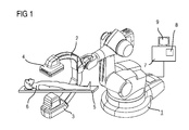
- interventional x-ray systems are used for imaging, the typical major features of which can be for example be a robot-controlled C-arm to which an x-ray tube and an x-ray detector are attached, a patient support table, a high-voltage generator for generating the tube voltages, a system control unit and a display system including at least one monitor.
- This type of C-arm x-ray system which is shown by way of example in FIG.
- a C-arm 2 typically features a C-arm 2 supported rotatably on a stand in the form of a six-axis industrial or articulated-arm robot 1 , attached to the ends of which are an x-ray source, for example an x-ray tube unit 3 with x-ray tubes and collimators, and an x-ray image detector 4 as an imaging unit.
- an x-ray source for example an x-ray tube unit 3 with x-ray tubes and collimators
- an x-ray image detector 4 as an imaging unit.
- the C-arm 2 can be adjusted spatially as required, for example by being turned around the center of rotation between the x-ray tube unit 3 and the x-ray detector 4 .
- the inventive x-ray system 1 to 4 is especially able to be rotated around centers of rotation and axes of rotation in the C-arm plane of the x-ray image detector 4 , preferably around a center point of the x-ray image detector 4 and around the center point of the axes of rotation intersecting with the x-ray image detector 4 .
- the known articulated-arm robot 1 has a base support which is mounted fixed on a floor for example.
- a carousel able to be rotated around a first axis of rotation is attached rotatably thereto.
- Attached to the carousel pivotably around a second axis of rotation is a robot motion link to which a robot arm is attached rotatably around a third axis of rotation.
- a robot hand is attached at the end of the robot arm rotatably around the fourth axis of rotation.
- the robot hand has an attachment element for the C-arm 2 which is able to be pivoted around a fifth axis of rotation and is rotatable around a sixth axis of rotation running at right angles thereto.
- the realization of the x-ray diagnostic device is not dependent on industrial robots Normal C-arm devices can also be used.
- the x-ray image detector 4 can be a rectangular or square, flat semiconductor detector which is preferably made of amorphous silicon (a-Si). Integrating and possibly scanning CMOS detectors can also be used.
- a-Si amorphous silicon
- a patient 6 Located as an examination object on a patient support table 5 in the beam path of the x-ray tube unit 3 , for recording an image of a heart for example, is a patient 6 to be examined.
- a system control unit 7 Connected to the x-ray diagnostic device is a system control unit 7 with an image system 8 which receives and processes the image signals of the x-ray image detector 4 (control elements are typically not shown). The x-ray images can then be viewed on a monitor 9 .
- a mask image 13 is initially created which contains the contrast medium-filled vascular tree 14 .
- one or more x-ray images are recorded which produce x-ray images without filling, so-called empty images 10 .
- fill images 11 are detected after contrast media have been injected, so-called fill images 11 .
- the mask image 13 is determined by means of a mask computation from the empty 10 and fill images 11 12 as mask M(i,j).
- the known moving weighted averaging can be used for this purpose, in which a percentage of the previous image is overlaid with the current image—possibly coupled to a movement detector.
- an “opacity” method is used, i.e. the respective darkest value of a pixel from all x-ray images is used in the mask image 13 .
- an object typically a wire, a catheter 16 or a “coil” is moved in a vessel of the vascular tree 14 .
- the object of the invention is to embody a method of the type mentioned at the start such that the roadmap method either achieves better contrast and an improved signal-to-noise ratio through improved averaging and opacity methods or also allows an improved timing behavior and thereby a faster creation of the mask image.
- the roadmap method improved in this way all x-ray images are first stored in the mask phase.
- the mask image is computed from these.
- all other parameters for activation of generator and x-ray image detector may be selected (e.g. dose, image frequency) as in the subsequent roadmap phase.
- each x-ray image is processed with the mask image into a roadmap image. If necessary information from a previous image (previous images) is also used.
- the processing of the individual empty and fill images in accordance with step d) can include the gray values of each pixel of x-ray images from the mask phase being arranged in ascending order.
- the value for each pixel can be selected independently or defined for each pixel by the typical gray value.
- Step f) can inventively include the detection of an object.
- step f) a further step in which the mask image is subjected to further image processing steps.
- the image sharpening or the noise reduction can be improved in a further step.
- the noise to be expected can be determined by measurements from a number of x-ray images, in which no contrast medium has yet been added, and/or can be determined from the gray values of an individual native image.
- FIG. 1 a known x-ray C-arm system for radiology, cardiology or neuro-surgery with an industrial robot as its support device,
- FIG. 2 a principle of the previously usual roadmap method with mask phase A (mask formation) and roadmap phase B (working phase) (state-of-the-art) and
- FIG. 3 a flow diagram of the inventive roadmap method.
- FIG. 3 shows the typical sequence of the inventively optimized x-ray method.
- mask phase A in which contrast media is generally injected into the vascular tree, x-ray images B k are recorded and initially stored. The mask image M is computed from the stored x-ray images B k .
- specific generator parameters and detector parameters such as image frequency, dose, tube focus, are used.
- roadmap phase B possibly with changed system parameters generator, x-ray detector—further x-ray images B l are recorded and processed with the mask image M into roadmap images R l .
- the mask phase can begin even from the first x-ray image.
- X-ray images 21 of the mask phase A which consist of empty images 10 and fill images 11 , are created by the x-ray system 20 with system control 7 , high-voltage generator, x-ray tube unit 3 and x-ray image detector 4 . These x-ray images 21 are all stored individually in a data memory 22 . In the further course of the mask phase A the individual x-ray images 21 are called up from the data memory 22 and a mask image 24 is created by image processing 23 , in which the complete vascular tree 14 with the anatomy, typically the bones, is to be seen.
- x-ray images 25 are created by the x-ray system 20 and supplied one after another to an image processor 26 one of the functions of which is to reproduce by means of negative overlaying roadmap images 27 on the monitor 9 , in which the vascular tree 14 as a roadmap and the introduced catheter 16 are to be seen.
- This method ensures that the maximum contrasts of the vessel filled at different times (lowest grade values) are stored in the mask image 24 M(i,j). In addition this method leads to a noise minimization since the mask values are entered with a “bias”—in this case always the lowest values.
- the mask image 24 M(i,j) can be subjected to further image processing steps for improving the contrast, image sharpening or noise reduction.
- N 1
- the K x-ray images do not first have to be stored but the analysis can be realized “on-the-fly”.
- the first image from a mask phase A possibly after synchronizing the dose regulation, is stored as mask image 24 .
- the great value of one pixel i,j is then replaced in the mask image 24 if it is darker than the grey value already contained there.
- This method can be improved by a local contrast enhancement precisely where contrast medium will be “measured”.
- the noise R(i,j) to be expected at each location of the image is determined. This can fluctuate from place to place through local dose variation—caused by more or less local absorption.
- the noise R(i,j) can be determined by measurement, for example in a number of x-ray images 21 , in which no contrast means has yet been added.
- the noise R(i,j) can be determined from the gray values of an individual native image, since then a first approximation and for sufficiently high doses the noise is proportional to the square root of the signal. It is now determined by comparison of S(i,j,) and R(i,j) in accordance with the metric (plausibility) whether contrast media has been applied in the corresponding pixel i,j. In general the standard deviation S(i,j) is somewhat greater than the noise R(i,j).
- the roadmap images RMl(i,j) l 1, L produced. See also FIG. 3 for the sequence.
- the mask computation must be adapted accordingly.
- the noise R could be determined by using reverse computation from the signal values of any of the x-ray images B (and use of calibration data to determine the proportionality factor between noise and signal independently of aspects such as tube voltage and detector mode).
- the dose increase can possibly also be accompanied by the choice of another, for example greater tube focus.
- each x-ray image B is processed with the mask image into a roadmap image R, either through an improved averaging and opacity methods a better contrast and improved noise behavior and/or an improved timing behavior and thereby a faster creation of the mask image can be achieved.
Abstract
Description
-
- The generation of the mask image (mask phase A) takes up to two seconds. This depends amongst other things on the image rate and the image post processing steps (such as the averaging method). The user (generally the radiologist) would like however, especially for embolizations, to see practically instantly how strongly the adhesive is running or whether it has already begun to harden and is no longer running.
- The averaging method (moving weighted average) reduces the maximum possible contrast of the contrast medium during the mask phase A in the smallest vessels (where the contrast medium only arrives during the last recordings within the series of
x-ray image 10 and 11).
- a) Recording of at least two empty images in a mask phase A with a matrix-type array of pixels,
- b) Recording of at least two fill images in mask phase A with a matrix-type array of pixels,
- c) Storage of the individual empty and fill images,
- d) Processing of the empty and fill images such that the gray values of each pixel of the x-ray images from mask phase A are arranged in ascending order,
- e) Computing a mask image from the processed empty and fill images such that the smallest gray values are averaged from which the mask image will be formed,
- f) Detecting at least one current x-ray image (fluoroscopy image),
- g) Subtracting (18, 26) the least one current x-ray image (15, 25) from the mask image (13, 24) for creation of roadmap images (19, 27) and
- h) Reproducing the roadmap images (19, 27).
M′(i,j)=c 1 *M(i,j), if S(i,j)>c 2 *R(i,j)
M′(i,j)=M(i,j), if S(i,j)<=c 2 *R(i,j)
with for a gray value less than c1=1.0, all pixels at which contrast media was determined becoming even darker, all other pixels not being changed, or for c2 greater than 1.0, a noise limiting being performed.
-
- Improved Averaging and Opacity Method
The following steps are to be executed: - Instead of a moving average method in which only the current x-ray image is computed with the last x-ray image, all
x-ray images 21 Bk(i,j) k=1,K are first stored during mask phase A. - Subsequently the gray values Gij(k) of each pixel i,j of the
x-ray images 21 Bk(i,j) k=1,K from mask phase A are arranged in ascending order. For each pixel an ordered array of grey values G′ij(k), k=1,K is produced. By this method the temporal course of the contrast medium in the vascular tree is decorrelated and the pixels at a given point in time in which the contrast medium was present at its strongest will lie at the bottom end of the ordered array. - As the next step the
mask image 24 is created. The smallest (darkest) N (with N<=K) grey values G′ij(n), n=1,N are averaged and a mask image 24 M is produced
M(i,j)=1/NΣG′ ij(n)
- Improved Averaging and Opacity Method
M′(i,j)=c 1 *M(i,j), falls S(i,j)>c 2 *R(i,j)
M′(i,j)=M(i,j), if S(i,j)<=c 2 *R(i,j).
-
- Improved Timing Behavior (Fastest Possible Mask Creation):
Higher image frequency during the mask phase a than in the “working phase” or roadmap phase B. If for example the image frequency in the roadmap phase B is 4 or 7.5 fps (frames per second) it can be increased in the mask phase A to 15 or 30 fps. This especially enables the control process of the x-ray system to be optimized before injection of the contrast medium into the vascular tree during thefirst x-ray images available x-ray images
- Improved Timing Behavior (Fastest Possible Mask Creation):
Claims (10)
M(i, j)=1/NΣG′ ij(n).
M′(i,j)=c 1 *M(i,j), if S(i,j)>c 2 *R(i,j)
M′(i,j)=M(i,j), if S(i,j)<=c 2 *R(i,j)
Applications Claiming Priority (3)
| Application Number | Priority Date | Filing Date | Title |
|---|---|---|---|
| DE102009031162 | 2009-06-30 | ||
| DE102009031162A DE102009031162B3 (en) | 2009-06-30 | 2009-06-30 | Interventional road map method for diagnostic examination of heart of patient in e.g. cardiology, involves subtracting actual X-ray image from mask images for producing road map images, and reproducing road map images |
| DE102009031162.9 | 2009-06-30 |
Publications (2)
| Publication Number | Publication Date |
|---|---|
| US20100329516A1 US20100329516A1 (en) | 2010-12-30 |
| US8620049B2 true US8620049B2 (en) | 2013-12-31 |
Family
ID=42309161
Family Applications (1)
| Application Number | Title | Priority Date | Filing Date |
|---|---|---|---|
| US12/821,344 Expired - Fee Related US8620049B2 (en) | 2009-06-30 | 2010-06-23 | Interventional roadmap method with optimization of the mask phase |
Country Status (2)
| Country | Link |
|---|---|
| US (1) | US8620049B2 (en) |
| DE (1) | DE102009031162B3 (en) |
Cited By (1)
| Publication number | Priority date | Publication date | Assignee | Title |
|---|---|---|---|---|
| US20100329523A1 (en) * | 2009-06-30 | 2010-12-30 | Martin Ostermeier | Method for computing a color-coded analysis image |
Families Citing this family (3)
| Publication number | Priority date | Publication date | Assignee | Title |
|---|---|---|---|---|
| DE102011083385A1 (en) * | 2011-09-26 | 2013-03-28 | Siemens Aktiengesellschaft | Method for performing digital subtraction angiography using x-ray device and control and display unit, involves predefining frame rate or x-ray dose per image and another frame rate |
| US20130172730A1 (en) * | 2011-12-29 | 2013-07-04 | Amit Cohen | Motion-Compensated Image Fusion |
| JP6598433B2 (en) * | 2014-06-26 | 2019-10-30 | キヤノンメディカルシステムズ株式会社 | X-ray diagnostic equipment |
Citations (3)
| Publication number | Priority date | Publication date | Assignee | Title |
|---|---|---|---|---|
| DE102005012700A1 (en) | 2005-03-18 | 2006-09-28 | Siemens Ag | X-ray device for use in operation theater, has x-ray source arrangement and x-ray detector, which are attached at common carrier that is attached at hand of robot having six rotation axes |
| US20060269134A1 (en) * | 2005-05-25 | 2006-11-30 | Microsoft Corporation | Preprocessing for information pattern analysis |
| US20100172474A1 (en) * | 2009-01-08 | 2010-07-08 | Florian Vogt | Method for pixel shift calculation in digital subtraction angiography and x-ray diagnostic imaging system for generating images in digital subtraction angiography |
Family Cites Families (3)
| Publication number | Priority date | Publication date | Assignee | Title |
|---|---|---|---|---|
| US5457728A (en) * | 1990-11-14 | 1995-10-10 | Cedars-Sinai Medical Center | Coronary tracking display |
| DE102006025917A1 (en) * | 2006-06-02 | 2007-12-06 | Siemens Ag | Object`s e.g. vascular tree of patient, outline determination method, involves determining brightness region between upper pixel values and lower pixel values representing objects e.g. vascular tree of patient, in histogram of x-ray image |
| DE102006048606A1 (en) * | 2006-10-13 | 2008-04-17 | Siemens Ag | X-ray image producing method for use in medical field, involves superimposing X-ray image on another X-ray image, and representing X-ray images periodically time-synchronously with body function according to type of film |
-
2009
- 2009-06-30 DE DE102009031162A patent/DE102009031162B3/en not_active Expired - Fee Related
-
2010
- 2010-06-23 US US12/821,344 patent/US8620049B2/en not_active Expired - Fee Related
Patent Citations (4)
| Publication number | Priority date | Publication date | Assignee | Title |
|---|---|---|---|---|
| DE102005012700A1 (en) | 2005-03-18 | 2006-09-28 | Siemens Ag | X-ray device for use in operation theater, has x-ray source arrangement and x-ray detector, which are attached at common carrier that is attached at hand of robot having six rotation axes |
| US20080240363A1 (en) | 2005-03-18 | 2008-10-02 | Siemens Aktiengesellschaft | X-ray device |
| US20060269134A1 (en) * | 2005-05-25 | 2006-11-30 | Microsoft Corporation | Preprocessing for information pattern analysis |
| US20100172474A1 (en) * | 2009-01-08 | 2010-07-08 | Florian Vogt | Method for pixel shift calculation in digital subtraction angiography and x-ray diagnostic imaging system for generating images in digital subtraction angiography |
Cited By (2)
| Publication number | Priority date | Publication date | Assignee | Title |
|---|---|---|---|---|
| US20100329523A1 (en) * | 2009-06-30 | 2010-12-30 | Martin Ostermeier | Method for computing a color-coded analysis image |
| US8948475B2 (en) * | 2009-06-30 | 2015-02-03 | Siemens Aktiengesellschaft | Method for computing a color-coded analysis image |
Also Published As
| Publication number | Publication date |
|---|---|
| US20100329516A1 (en) | 2010-12-30 |
| DE102009031162B3 (en) | 2010-08-05 |
Similar Documents
| Publication | Publication Date | Title |
|---|---|---|
| US8509384B2 (en) | Method for enhanced visualization of objects in interventional angiographic examinations | |
| US7221735B2 (en) | Radiographic image capturing apparatus, radiographic image display apparatus, and methods thereof | |
| JP5361410B2 (en) | Image processing device | |
| JP5393245B2 (en) | Image processing apparatus, image processing apparatus control method, X-ray image capturing apparatus, and X-ray image capturing apparatus control method | |
| US8299413B2 (en) | Method for pixel shift calculation in digital subtraction angiography and X-ray diagnostic imaging system for generating images in digital subtraction angiography | |
| US6792159B1 (en) | Correction of defective pixels in a detector using temporal gradients | |
| EP0362821A1 (en) | Diagnostic X-ray apparatus | |
| US8463013B2 (en) | X-ray diagnosis apparatus and image reconstruction processing apparatus | |
| JPH0511471B2 (en) | ||
| JP5042887B2 (en) | Radiation imaging equipment | |
| KR20160094273A (en) | Radiographic system and radiographic method | |
| US9084543B2 (en) | X-ray diagnostic apparatus | |
| US8620049B2 (en) | Interventional roadmap method with optimization of the mask phase | |
| US9194965B2 (en) | System and method for X-ray image acquisition and processing | |
| US20140193082A1 (en) | Image processing apparatus and method | |
| US7295652B2 (en) | X-ray image diagnostic apparatus | |
| JP4366177B2 (en) | Method and apparatus for correcting retained image artifacts | |
| US6246746B1 (en) | X-ray examination apparatus with X-ray image sensor matrix and correction unit | |
| JP6129517B2 (en) | X-ray diagnostic apparatus and control program | |
| JP4210464B2 (en) | X-ray diagnostic imaging equipment | |
| JPH05192319A (en) | X-ray diagnostic device | |
| US20110038518A1 (en) | Roadmap method for the superimposed representation of images | |
| JP2020036819A (en) | X-ray imaging apparatus and X-ray image processing method | |
| JPWO2019053935A1 (en) | Radiography equipment | |
| US20040228444A1 (en) | X-ray diagnostic apparatus with image computer for direction filtering |
Legal Events
| Date | Code | Title | Description |
|---|---|---|---|
| AS | Assignment |
Owner name: SIEMENS AKTIENGESELLSCHAFT, GERMANY Free format text: ASSIGNMENT OF ASSIGNORS INTEREST;ASSIGNORS:LEIBLEIN, RUDOLF;SPAHN, MARTIN;REEL/FRAME:024580/0419 Effective date: 20100519 |
|
| STCF | Information on status: patent grant |
Free format text: PATENTED CASE |
|
| AS | Assignment |
Owner name: SIEMENS HEALTHCARE GMBH, GERMANY Free format text: ASSIGNMENT OF ASSIGNORS INTEREST;ASSIGNOR:SIEMENS AKTIENGESELLSCHAFT;REEL/FRAME:039271/0561 Effective date: 20160610 |
|
| FPAY | Fee payment |
Year of fee payment: 4 |
|
| FEPP | Fee payment procedure |
Free format text: MAINTENANCE FEE REMINDER MAILED (ORIGINAL EVENT CODE: REM.); ENTITY STATUS OF PATENT OWNER: LARGE ENTITY |
|
| LAPS | Lapse for failure to pay maintenance fees |
Free format text: PATENT EXPIRED FOR FAILURE TO PAY MAINTENANCE FEES (ORIGINAL EVENT CODE: EXP.); ENTITY STATUS OF PATENT OWNER: LARGE ENTITY |
|
| STCH | Information on status: patent discontinuation |
Free format text: PATENT EXPIRED DUE TO NONPAYMENT OF MAINTENANCE FEES UNDER 37 CFR 1.362 |
|
| FP | Lapsed due to failure to pay maintenance fee |
Effective date: 20211231 |