US8614707B2 - 3D and real time electrical capacitance volume-tomography sensor design and image reconstruction - Google Patents
3D and real time electrical capacitance volume-tomography sensor design and image reconstruction Download PDFInfo
- Publication number
- US8614707B2 US8614707B2 US11/909,548 US90954806A US8614707B2 US 8614707 B2 US8614707 B2 US 8614707B2 US 90954806 A US90954806 A US 90954806A US 8614707 B2 US8614707 B2 US 8614707B2
- Authority
- US
- United States
- Prior art keywords
- dimensional
- sensor device
- capacitance sensor
- image
- electrodes
- Prior art date
- Legal status (The legal status is an assumption and is not a legal conclusion. Google has not performed a legal analysis and makes no representation as to the accuracy of the status listed.)
- Active, expires
Links
Images


Classifications
-
- G—PHYSICS
- G06—COMPUTING OR CALCULATING; COUNTING
- G06T—IMAGE DATA PROCESSING OR GENERATION, IN GENERAL
- G06T12/00—Tomographic reconstruction from projections
- G06T12/20—Inverse problem, i.e. transformations from projection space into object space
-
- A—HUMAN NECESSITIES
- A61—MEDICAL OR VETERINARY SCIENCE; HYGIENE
- A61B—DIAGNOSIS; SURGERY; IDENTIFICATION
- A61B5/00—Measuring for diagnostic purposes; Identification of persons
- A61B5/05—Detecting, measuring or recording for diagnosis by means of electric currents or magnetic fields; Measuring using microwaves or radio waves
- A61B5/053—Measuring electrical impedance or conductance of a portion of the body
- A61B5/0535—Impedance plethysmography
-
- G—PHYSICS
- G01—MEASURING; TESTING
- G01N—INVESTIGATING OR ANALYSING MATERIALS BY DETERMINING THEIR CHEMICAL OR PHYSICAL PROPERTIES
- G01N27/00—Investigating or analysing materials by the use of electric, electrochemical, or magnetic means
- G01N27/02—Investigating or analysing materials by the use of electric, electrochemical, or magnetic means by investigating impedance
- G01N27/22—Investigating or analysing materials by the use of electric, electrochemical, or magnetic means by investigating impedance by investigating capacitance
- G01N27/226—Construction of measuring vessels; Electrodes therefor
-
- G—PHYSICS
- G01—MEASURING; TESTING
- G01N—INVESTIGATING OR ANALYSING MATERIALS BY DETERMINING THEIR CHEMICAL OR PHYSICAL PROPERTIES
- G01N33/00—Investigating or analysing materials by specific methods not covered by groups G01N1/00 - G01N31/00
- G01N33/15—Medicinal preparations ; Physical properties thereof, e.g. dissolubility
-
- G—PHYSICS
- G01—MEASURING; TESTING
- G01N—INVESTIGATING OR ANALYSING MATERIALS BY DETERMINING THEIR CHEMICAL OR PHYSICAL PROPERTIES
- G01N33/00—Investigating or analysing materials by specific methods not covered by groups G01N1/00 - G01N31/00
- G01N33/24—Earth materials
-
- G—PHYSICS
- G06—COMPUTING OR CALCULATING; COUNTING
- G06T—IMAGE DATA PROCESSING OR GENERATION, IN GENERAL
- G06T2211/00—Image generation
- G06T2211/40—Computed tomography
- G06T2211/412—Dynamic
-
- G—PHYSICS
- G06—COMPUTING OR CALCULATING; COUNTING
- G06T—IMAGE DATA PROCESSING OR GENERATION, IN GENERAL
- G06T2211/00—Image generation
- G06T2211/40—Computed tomography
- G06T2211/424—Iterative
-
- G—PHYSICS
- G06—COMPUTING OR CALCULATING; COUNTING
- G06T—IMAGE DATA PROCESSING OR GENERATION, IN GENERAL
- G06T2211/00—Image generation
- G06T2211/40—Computed tomography
- G06T2211/428—Real-time
Definitions
- the present invention generally relates to process tomography and, in particular, relates a dynamic three-dimensional image electrical capacitance tomography.
- the recent progress in the development of such measuring techniques as process tomography has provided more insights into complex multiphase flow phenomena in many industrial processes often in a combination gas, liquid and solid states, including pneumatic conveying, oil pipe lines, fluidized beds, bubble columns and many other chemical and biochemical processes.
- the technique is capable of monitoring and control, both continuously and simultaneously, the local and global dynamic behavior of gas bubbles and solid particles in a non-invasive manner.
- electrical tomography including capacitive, conductive or inductive modalities, is the most promising technical for dynamic flow imaging purpose.
- the technique has a relative high temporal resolution, up to a few milliseconds, with sufficient spatial resolution, up to 1 to 3% of column diameter.
- Tomography technique in general, generates a two-dimensional image called a “tomogram” (i.e., a two-dimensional (2D) image).
- a three-dimensional image of an object is usually generated by stacking up the tomograms.
- This is termed “static” three-dimensional (3D) imaging, because the 3D image could only be generated from a static or slow moving object. Therefore, this 3D imaging cannot be applied to situations with a fast moving object, or highly fluctuating multiphase flow media.
- 3D imaging cannot be applied to situations with a fast moving object, or highly fluctuating multiphase flow media.
- the tomogram is reconstructed from a capacitance sensor, which is in fact, geometrically three-dimensional.
- slice imaging is not possible for ECT due to the extended length of the electrode.
- the obtained 2D image is a result from projections of the object on a cross-section by assuming no variation in the axial direction. Therefore, the 2D ECT is actually unreal in the sense that the three-dimensional object needs to be assumed to have an infinite length. This is one of the major drawbacks of conventional ECT, and becomes problematic when the variation in the permittivity along the axial direction is significant.
- electrical tomography either resistance or capacitance, has a potential for volumetric imaging, as electrical current or wave, spreads to the three-dimensional space.
- the “soft-field” effect of the electrical field is once considered as one disadvantage of the technique for imaging applications, but it may be advantageous to realize the volumetric imaging based on tomography technique.
- electrical tomography is typically implemented based on measurements of a single constitutive property (i.e., permittivity for capacitance tomography, conductivity for resistive and impedance tomography and permability for induction tomography).
- a single constitutive property i.e., permittivity for capacitance tomography, conductivity for resistive and impedance tomography and permability for induction tomography.
- Multimodal tomography is generally implemented through three different strategies: (1) integration of two or more tomography hardware sensors into one imaging system (e.g., gamma-ray and ECT tomography), (2) use of reconstruction techniques capable of differentiating between different phases based on the same sensing signal (e.g., NN-MOIRT), and (3) use of the same sensor hardware to acquire different signals corresponding to different electrical properties (impendence tomography sensors for imaging permittivity and conductivity).
- the first strategy is fast, it has the major disadvantage in terms of its high cost and complexity (added hardware).
- the data acquisition needs to be carefully coordinated to yield consistent data at different given time frames for real-time applications.
- the second strategy is the least costly to implement.
- the third strategy is inherently multi-modal since it provides all the required information (on the different electrical properties) using the same sensor hardware and same reconstruction technique.
- integration of such systems with multi-modal reconstruction techniques can provide independent data for different phases in the imaging domain. For example, obtaining both capacitive and conductive (impedance) flow information simultaneously is beneficial in many applications. This is particularly true when the flow under consideration is a mixture of phases with widely different conductivity and permittivity constants, such as oil flow in a pipeline.
- EIT Electrical impedance tomography
- ECVT electrical capacitance volume-tomography
- dynamic three-dimensional image electrical capacitance tomography sensor system is disclosed.
- the technique generates, from the measured capacitance, a whole volume image of the region enclosed by the a geometrically three-dimensional capacitance sensor.
- a real time, three-dimensional imaging of a moving object or a real time volume imaging i.e., four-dimensional (4D)
- 4D four-dimensional
- the system comprises a three-dimensional capacitance sensor, data acquisition electronics and the image reconstruction algorithm which enables the volume-image reconstruction.
- the electrode shape of the capacitance sensor can be rectangular, triangular, trapezium, or any shape that encloses a three-dimensional section of the measuring domain and that distributes the electrical field intensity in three directions with equal sensitivity strength or comparable sensitivity strength.
- the image reconstruction algorithm reconstructs simultaneously the image voxels in a three-dimensional array.
- the tomography sensor system may also be multimodal.
- ECVT is also applicable for 3D medical imaging of the human body.
- ECVT is also feasible for real time imaging of multiphase flow systems.
- ECVT is also feasible interrogation of the whole vessel or conduit with an arbitrary shape of geometry.
- FIGS. 1A-B illustrate possible sensor designs according to one embodiment of the present invention.
- FIG. 1C illustrates volume image digitization according to one embodiment of the present invention.
- FIG. 2 illustrates three-dimensional sensitivity maps according to one embodiment of the present invention.
- FIG. 3 illustrates axial sensitivity distribution for all capacitance readings according to one embodiment of the present invention.
- FIG. 4A illustrates reconstruction results for a sphere object using NN-MOIRT according to one embodiment of the present invention.
- FIG. 4B illustrates reconstruction results for a sphere and one half of a sphere using NN-MOIRT according to one embodiment of the present invention.
- FIG. 4C illustrates reconstruction results for a dielectric block using NN-MOIRT according to one embodiment of the present invention.
- FIG. 5 illustrates reconstruction results for a sphere in the center and the edge of sensing domain using the LBP technique according to one embodiment of the present invention.
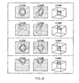
- FIG. 6 illustrates reconstruction results for a sphere in the center and the edge of sensing domain using the Landweber technique according to one embodiment of the present invention.
- FIG. 7 illustrates reconstruction results for a sphere in the center and the edge of sensing domain using NN-MOIRT according to one embodiment of the present invention.
- FIG. 8 illustrates a 3D image of a falling sphere reconstructed using the Landweber technique according to one embodiment of the present invention.
- FIG. 9 illustrates a 3D image of a falling sphere reconstructed using NN-MOIRT according to one embodiment of the present invention.
- FIG. 10 illustrates snapshots of 3D volume images of gas-liquid flow in a bubble column according to one embodiment of the present invention.
- FIG. 11 illustrates snapshots of volume image of bubble in gas-solid fluidized bed using group B particles according to one embodiment of the present invention.
- FIG. 12 illustrates different electrode designs according to one embodiment of the present invention.
- FIG. 13 illustrates different capacitance sensor designs for ECVT applications according to one embodiment of the present invention.
- FIG. 14 illustrates reconstruction of the simulated data for the diffusion case in multimodal tomography according to one embodiment of the present invention.
- FIG. 15 illustrates reconstruction of simulated data for the conviction case in multimodal tomography according to one embodiment of the present invention.
- a technique to reconstruct simultaneously a volume image of a region inside a vessel from capacitance measurement data using capacitive sensor electrodes attached on the wall of the vessel is developed. Due to the “soft field” nature of the electrical field, the capacitance measurements can be made using arbitrary shapes of electrodes and vessels.
- volume tomography instead of 3D tomography stems from the fact that the technique generates simultaneous information of the volumetric properties within the sensing region of the vessel with an arbitrary shape. The terminology is also chosen to differentiate the technique from a “static” 3D or quasi-3D tomography technique.
- the development of the technique primarily includes the evalution of the capacitance tomography sensor design and volume image reconstruction algorithm. The tests on capacitance data set obtained from actual measurements are also shown to demonstrate the validity of the technique for real time, volume imaging of a moving object.
- An ECT sensor generally consists of n electrodes placed around the region of interest, providing n(n ⁇ 1)/2 independent mutual capacitance measurements used for image reconstruction. Unlike usual EIT sensors that use direct current injection as excitation signal, ECT sensors rely on a time varying driving signal for capacitance measurements.
- C ij 1 ⁇ ⁇ ⁇ V ij ⁇ ⁇ ⁇ j ⁇ ⁇ ⁇ ⁇ ⁇ ⁇ n ⁇ ⁇ d l ( 2 )
- C ij represents the mutual capacitance between electrodes i and j
- ⁇ V ij the potential difference
- ⁇ j is a closed surface (or path in 2-D as considered here) enclosing the detecting electrode
- ⁇ circumflex over (n) ⁇ is the unit vector normal to ⁇ j .
- the r.m.s. power dissipated by a conductive object in the domain of interest is given by:
- Equations (2) and (3) relate the permittivity and conductivity distributions to the boundary measurements of capacitance and power, respectively.
- the solutions of both equations given a ⁇ (x, y) and ⁇ (x, y) distribution constitutes the forward problem solution.
- the process of obtaining ⁇ (x, y) and ⁇ (x, y) distributions from the boundary measurements is the inverse problem.
- the electrical capacitance tomography involves tasks of collecting capacitance data from electrodes placed around the wall outside the vessel (forward problem) and reconstructing image based on the measured capacitance data (inverse problem).
- the measured capacitance C i of the i-th pair between the source and the detector electrodes is obtained by integrating Equation 4:
- Equation 5 relates dielectric constant (permittivity) distribution, ⁇ (x,y,z), to the measured capacitance C i .
- linearization techniques provide accurate and relatively fast solutions, they are limited to very simple geometries with symmetric permittivity distributions, and are not applicable to industrial tomography systems with complex dynamic structures.
- numerical methods can provide fairly accurate solutions for arbitrary property distributions. They, however, consume excessive computational time which is impractical for tomography application with iterative image reconstruction.
- linearization methods provide relatively fast and simple solution, though they show a smoothing effect on a sharp boundary of the reconstructed image. The smoothing effect is improved with iteration in the image reconstruction process.
- Equation 6 Equation 6
- sensitivity The integration part divided by the voltage difference is called as sensitivity, which can be derived as:
- the sensitivity matrix S has a dimension of M ⁇ N.
- the image reconstruction process is an inverse problem involving the estimation of the permittivity distribution from the measured capacitance data.
- Equation 9 if the inverse of S exists, the image can be easily calculated.
- G S T C (9)
- the problem is ill-posed, i.e., there are fewer independent measurements than unknown pixel values, so that the inverse matrix of S does not exist.
- the simplest way to estimate the image vector is using a back projection technique, i.e., in Equation 9, all measurement data are simply back-projected (added up) to estimate the image. This technique is referred to as linear back projection (LBP).
- LBP linear back projection
- the iterative image reconstruction process involves finding methods for estimating the image vector G from the measurement vector C and to minimize the error between the estimated and the measured capacitance, under certain conditions (critera), such that: SG ⁇ C (10)
- a linear back projection ILBP
- the technique aims at finding image vector G which minimizes the following least square error function, Equation 11.
- ⁇ k is a penalty factor of iteration k-th, which is usually chosen to be constant.
- the capacitance difference ⁇ C becomes insignificant, and the image is iteratively corrected by the sensitivity S T , producing the so-called “sensitivity-caused artifacts.”
- the generated image seems to be directed toward the stronger side of sensitivity. This is why the reconstructed image based on Landweber technique has a better resolution near the wall (higher sensitivity) than the center region (lower sensitivity).
- a multi-criterion optimization based image reconstruction technique for solving the inverse problem of 2D ECT is extended to solve the inverse problem of the 3D ECT.
- the optimization problem finds the image vector that minimizes simultaneously the four objective functions: negative entropy function, least square errors, smoothness and small peakedness function, and 3-to-2D matching function.
- all the other functions involved in the reconstruction process collectively define the nature of the desired image based on the analysis of the reconstructed image.
- the error which is generated from the linearized forward solver and propagated to the reconstructed image through the least square objective function, is minimized with the other objective functions applied.
- Equation 14 The least weighted square error of the capacitance measurement is defined in Equation 14:
- Equation 15 The smoothness and small peakedness function is defined as in Equation 15:
- Equation 16 An additional objective function for the 3D image reconstruction is required to match the 3D reconstructed image to the 2D, namely 3-to-2D matching function. which is defined in Equation 16 as:
- H 2D projection matrix from 3D to 2D, having dimensions of N ⁇ N 2D .
- N 2D is the number of voxels in one layer of the 3D volume image vector G.
- ⁇ 4 is a constant between 0 and 1.
- the 2D image vector is the 2D solution of the inverse problem in the image reconstruction.
- the multi-criteria optimization for the reconstruction problem is to choose an image vector for which the value of the multi-objective functions are minimized simultaneously.
- Hopfield and Tank proposed a technique based on a neural network model to solve optimization problem and in particular they presented a mapping of the traveling salesman problem onto neural networks. Since then, Hopfield neural networks model (or simply called Hopfield nets) has been used to successfully address a number of difficult optimization problems, including image restoration and image reconstruction for “hard field” tomography and “soft field” tomography. Their advantages over more traditional optimization techniques lie in their potential for rapid computational power when implemented in electrical hardware and inherent parallelism of the network.
- the image voxel value G j to be reconstructed is mapped into the neural output variable v j in the Hopfield nets.
- ⁇ is a steepness gain factor that determines the vertical slope and the horizontal spread of the sigmoid-shape function.
- the behavior of a neuron in the network is characterized by the time evolution of the neuron state u j governed by the following differential Equation 19:
- C 0j is an associated capacitance in the j-th neuron
- E(G) is the total energy of the Hopfield nets.
- the overall energy function of the network includes a sum of the constraint functions (objective functions) to penalize violation of the constraints.
- the overall networks energy function corresponding to the optimization problem above becomes Equation 21:
- Equation 21 The first term in Equation 21 is the interactive energy among neurons based on the objective functions described above.
- the second term is related to the violation constraints (penalty functions) to the three weighted square error functions which must also be minimized.
- the third term encourages the network to operate in the interior of the N-dimensional unit cube (0 ⁇ G j ⁇ 1) that forms the state space of the system.
- N is the number of neurons in the Hopfield nets, which is equal to the number of voxels in the digitized volume image.
- the constraint function ⁇ ( ⁇ k z k ) ⁇ ( ⁇ k z k,i ) which is defined in Equation 22 as:
- Equation 23 Equation 23:
- Equation 23 can be solved, for example, using Euler's method to obtain time evolution of the network energy.
- ⁇ 0 k , ⁇ k and ⁇ k are positive constants.
- the penalty parameter provides a mechanism for escaping local minima by varying the direction of motion of the neurons in such a way that the ascent step is taken largely by the penalty function in the initial steps.
- the value of the penalty factor reduces as the algorithm proceeds.
- u j ′ ⁇ ( t ) - u ⁇ ( t ) ⁇ - ⁇ 1 ⁇ W 1 ⁇ ⁇ 1 + ln ⁇ ⁇ G ⁇ ( t ) ⁇ - ⁇ 2 ⁇ W 2 ⁇ S T ⁇ z 1 - ⁇ 3 ⁇ W 3 ⁇ ⁇ XG ⁇ ( t ) + G ⁇ ( t ) ⁇ - ⁇ 4 ⁇ W 4 ⁇ H 2 ⁇ D T ⁇ z 2 - S T ⁇ ⁇ ( ⁇ 1 ⁇ z 1 - H 2 ⁇ D , T ⁇ ⁇ ⁇ ( ⁇ 2 ⁇ z 2 ) ⁇ ⁇ ⁇
- the neuron output corresponds to the voxel value is updated as Equation 26:
- ⁇ ′ ⁇ (u) d ⁇ ⁇ (u j )/du.
- the stopping rule is used when the changes in the firing rates become insignificant, i.e., for all voxels
- the first step is preprocessing by solving the 2D image matrices in Equation 16 using NN-MOIRT.
- the steepness gain factor ⁇ is set to 2.
- the initial weights are
- ⁇ ⁇ 2 ( 0 ) [ 1 2 ⁇ ⁇ SG ⁇ ( 0 ) - C ⁇ 2 ] - 1
- ⁇ ⁇ 3 ( 0 ) [ 1 2 ⁇ G T ⁇ ( 0 ) ⁇ XG ⁇ ( 0 ) + 1 2 ⁇ G T ⁇ ( 0 ) ⁇ G ⁇ ( 0 ) ] - 1
- ⁇ ⁇ 4 ( 0 ) [ ⁇ H 2 ⁇ D ⁇ G ⁇ ( 0 ) - G 2 ⁇ D ⁇ ( t ) ⁇ 2 + ⁇
- ⁇ ⁇ 2 ( t + ⁇ ⁇ ⁇ t ) [ 1 2 ⁇ ⁇ SG ⁇ ( t ) - C ⁇ 2 ] - 1
- ⁇ ⁇ 3 ( t + ⁇ ⁇ ⁇ t ) [ 1 2 ⁇ G T ⁇ ( t ) ⁇ XG ⁇ ( t ) + 1 2 ⁇ G T ⁇ ( t ) ⁇ G ⁇ ( t ) ] - 1
- ⁇ ⁇ 4 ( t + ⁇ ⁇ ⁇ t ) [ ⁇ H 2 ⁇ D ⁇ G ⁇ ( t ) - G 2 ⁇ D ⁇ ( t ⁇ ) ⁇ 2 + ⁇ H 1 ⁇ D
- the image vector is then updated using the iteration process in Equation 23. The updating procedure is repeated until the error is minimized.
- the image reconstruction procedure is stopped when the termination scalar is determined to be
- the sensitivity matrix In two-dimensional ECT, the sensitivity matrix only has variation in radial (i.e., x- and y-axes) directions, assuming infinite length of the electrode in the z-direction. Imaging a three-dimensional object requires a sensitivity matrix with three-dimensional variation, especially in the axial (z-axis) direction to differentiate the depth along the sensor length. Therefore, the fundamental concept of the electrical capacitance sensor design for the 3D volume imaging is to distribute equally the electrical field intensity (sensitivity) all over the three-dimensional space (control volume) or with comparable electrical field intensity strength. This concept relates to the sensitivity variance (the difference between the maxima and minima) and the sensitivity strength (the absolute magnitude).
- FIGS. 1 a and 1 b Two sensor designs are described and their performances for 3D volume imaging evaluated, i.e., a 12-electrode triangular sensor arranged in one plane and a 12-electrode rectangular sensor arranged in triple planes as illustrated in FIGS. 1 a and 1 b .
- the triangular sensor in FIG. 1 a comprises a triangular shape 1 electrode that forms six panels of two sensors 7 and 8 .
- the choice of the electrode number is based on the data acquisition system available which has 12 channels. However, the use of any other number of electrodes is possible.
- different shaped sensors such as trapezoidal or any other shape or combination of different shapes, to enclose the 3D sensor region are also feasible as long as the sensor provides three-dimensional sensitivity distribution with relatively equal order of sensitivity strength or with comparable sensitivity strength.
- the electrodes are arranged in three planes where each plane is shifted to another to distribute the electrical field intensity more uniformly in the axial direction and to increase the radial resolution up to twice the radial resolution of a 4-electrode sensor.
- the radial resolution of the rectangular sensor with this electrode arrangement thus equals 8-electrode sensor per plane.
- the number of planes also can be greater than two to provide better variation in the axial direction.
- trapezoidal, triangular or any non-rectangular geometric shape sensors it is also possible to use just a single plane.
- the sensitivity maps of the two capacitance sensors are illustrated in FIG. 2 .
- the sensitivity maps show distributions of sensitivity variation in three-dimensional space.
- the sensitivity maps of capacitance readings between any electrode pair have a three-dimensional variation.
- the maps show relatively comparable axial and radial sensitivity variation for the rectangular sensor, but less equally for the triangular sensor. Equal sensitivity variation all over the sensing domain is essential to avoid an artifact or image distortion in the reconstruction result due to inequality in the sensitivity strength distribution.
- the largest magnitude in the sensitivity is found in the same-plane electrode pair capacitance reading, while the lowest is in the electrode pair between the first and third layers.
- the magnitude of the sensitivity strength does not affect significantly the image reconstruction process but it relates largely to the Signal-to-Noise Ratio (SNR) in the capacitance measurement.
- SNR Signal-to-Noise Ratio
- the sensitivity strength in the first and third layers of electrode pairs is one order less in magnitude than that of the same-plane electrode pair. Therefore, the capacitance measurement between the first and third planes is very sensitive to noise. Therefore, the sensor requires very careful manufacture.
- the capacitance measurement between inter-plane electrode pair is related mostly to the horizontal length of the rectangular electrode, and is almost independent of the axial length of the electrode. Therefore, a consideration of the horizontal length of the electrode must be given in manufacturing the rectangular sensor.
- FIG. 3 illustrates the axial sensitivity distribution for all 66 electrode pairs for both sensors. Not much variation is observed for the triangular sensor in the middle of the sensing zone. This region gives no differentiation in the image reconstruction process and becomes a dead-zone in which a convergence is difficult to achieve.
- the dead zones are found in the bottom (layer numbers 1 to 3 ) and the top (layer numbers 18 to 20 ) portions of the sensor domain. The dead zones for the rectangular sensor can be removed by considering only the effective volume of the sensing domain, i.e., layers 4 to 17 . All reconstructed images for the rectangular sensor, unless otherwise stated, belong to the effective sensor domain.
- a dual sensitivity matrix (capacitance plus power measurement data) can be constructed and used for solving both forward and inverse problems.
- the dual matrix elements are approximated based on the electric field distribution in the empty sensor scenario.
- the difference in capacitance is related directly to the difference in total stored energy caused by the permittivity pixel.
- This energy difference is composed of two components: internal to the pixel ⁇ W int and external to the pixel ⁇ W ext .
- the constants ⁇ int and ⁇ ext are introduced to simplify the final equations. Combining both energy components, we have:
- ⁇ ⁇ ⁇ C 2 ( ⁇ ⁇ ⁇ V ) 2 ⁇ ( ⁇ ext + ⁇ int ) ⁇ ⁇ E ⁇ 0 ⁇ 2 , ( 27 )
- the capacitance difference introduced by a small perturbation in permittivity is proportional to the square of the unperturbed electric field (empty vessel).
- the sensor model has to be solved once in the empty case.
- each element in the power matrix linearizes the relation between the conductive (heating) loss and a small conductive pixel perturbation in an insulating background given by 3, integrated over the (small) pixel volume having conductivity.
- the dissipated power inside the pixel is calculated based on the electric field in the empty sensor case.
- the same field solution used for calculating the capacitance sensitivity matrix can be used here for calculating the power sensitivity matrix.
- a 12-channel data acquisition system (DAM200-TP-G, PTL Company, UK) can be used.
- the ECT system comprises a capacitance sensor, sensing electronics for data acquisition and a processing system for image reconstruction.
- the sensors can include two types of 12-electrode systems as illustrated in FIG. 1 .
- the length of the sensing domain of the capacitance sensor can be about 10 cm with a column diameter of about 10 cm.
- the data acquisition system can be capable of capturing image data up to about 80 frames per second.
- the image is reconstructed on a 20 ⁇ 20 ⁇ 20 resolution based on the algorithm described above.
- the volume image digitization is illustrated in FIG. 1 c.
- An ECT sensor was used to assess the multimodal tomography system performance.
- the sensor operates at about 10 MHz.
- Simulations for sensitivity calculations and boundary measurements can be carried out using FEM.
- a dual sensitivity matrix for capacitance and power perturbations was constructed based on the electric field solution of the sensor in its empty state.
- the reconstruction process, data forward simulations, and data post-processing can be processed on a Pentium IV computer, with a 3 GHZ processor and with a 3 GB RAM memory.
- FIG. 4 illustrates the three-dimensional reconstruction results of a dielectric sphere, a one and half sphere and a dielectric block based on simulated capacitance data using NN-MOIRT algorithms.
- the diameters of both spheres are half the diameter of the sensor equaling the whole dimension of the image.
- the sensor used was a 12-electrode twin-plane triangular sensor. Excellent agreements between the reconstructed 3D images and the model images were obtains for all images.
- the reconstruction results from measurement data are shown in FIGS. 5-7 using the two electrode designs illustrated in FIG. 1 and the three reconstruction algorithms: LBP, Landweber (or ILBP), and NN-MOIRT.
- LBP Landweber
- NN-MOIRT NN-MOIRT
- the iteration number was set to 100 in all cases.
- the reconstructions are based on actual capacitance measurements of dielectric objects: one sphere located in the center of the sensing domain and another sphere located half inside the sensing domain.
- Each row in every figure contains two slice images of X-Z and Y-Z cuts in the first two columns and one 3D image in the third column.
- the 3D image can be an isosurface display with an isovalue of half of the maximum permittivity.
- FIG. 5 illustrates the reconstruction results on the LBP technique. Elongation in axial direction of the reconstructed images occurs to both the objects for the single-plane triangular sensor.
- the axial elongation effect is expected as the sensitivity variation in the axial direction for the triangular electrode is insignificant as compared to that in the radial direction (see FIG. 3 a ).
- the technique gives relatively accurate shapes of the objects through a smoothing effect appears in the sharp boundary of the reconstructed images.
- the contrasts between low and high permittivity regions in the reconstructed images are relatively uniform in both radial and axial direction.
- FIG. 6 illustrates the reconstruction results for the Landweber technique (or iterative LBP).
- the reconstructed images are severely distored in all cases for both sensor designs.
- An elongation effect is also observed for the triangular sensor.
- the reconstructed images appear to be directed toward the sensing sites with relatively stronger sensitivities, which correspond to the junctions between electrodes, causing a distortion and elongation due to a “sensitivity-caused artifact” as described above.
- the distortion may also arise from noises contained in the capacitance data.
- the reconstructed volume images using the NN-MOIRT algorithm are illustrated in FIG. 7 .
- the triangular sensor although the elongation effect is still observed, the results are much better compared to those using LBP and Landweber techniques.
- the effect of noise to the reconstructed image is also minimal as compared to the Landweber technique.
- the reconstructed images are almost perfect except for the contrast which is less clear as compared to the triangular sensor.
- the spatial resolution for the rectangular electrode is decreased, resulting in less contrast in the reconstructed image.
- Increasing the number of electrodes per plane for the rectangular sensor can increase the contrast between low and high permittivities in the reconstructed image.
- FIGS. 8 and 9 show a series of instantaneous volume-image of the same dielectric sphere used in FIG. 5-7 when falling through the inside of the sensor based on image reconstruction results using the Landweber technique and NN-MOIRT.
- a distortion in the shape of the reconstructed images from level to level is observed in the Landweber technique results.
- the shape of the reconstructed images using NN-MOIRT is relatively conserved at every level, verifying the capability of the algorithm to resolve, to some extent, the effect of “sensitivity-cause artifact.” This result also indicates that the technique requires fewer measurement data to generate the same image quality as produced by the Landweber technique.
- FIG. 10 shows a snapshot of the tomography volume image (3D gas concentration distribution) of the multiphase flow.
- the tomography volume image is constructed from permittivity voxel values in 4D matrix components, i.e., three space components with spatial resolution of 5 ⁇ 5 ⁇ 8 mm 3 and one time component with a temporal resolution of 12.5 ms.
- the voxel permittivity values are converted into phase concentration (holdup) of the multiphase system based on the capacitance model described above.
- the first two figures in the top row are slice cut images of the planes defined by the coordinate system in the bottom-right in the figure.
- the first and second figures in the bottom row are, respectively, a 3D volume image which is partly cut-off to display the inside of the 3D representation and a 3D isosurface image which displays the 3D boundary (surface) of the bubble swarm image.
- the cut-off boundary value was set at 10% of the gas holdup value.
- the cut-off boundary selection was arbitrary and used to provide some sense of distinction of the boundary of high-concentration bubble swarm from the surrounding low gas concentration region.
- a photograph of the two-phase flow was taken using a high-speed digital video camera under the same conditions is displayed on the right-hand side of the figure.
- FIG. 11 An example of the application result of the technique for multiphase flow imaging of gas-solid flow in a vertical column is illustrated in FIG. 11 , showing a well-known apple shape image of a bubble in gas-solid fluidization system as compared with a 1D X-ray photograph.
- the image confirms the accuracy and quickness in real-time volume-imaging of moving dielectric objects.
- FIGS. 12( a - c ) illustrate different designs of capacitance electrodes selected based on different shapes of control volume and imaging purposes.
- the technique is feasible for volume imaging of multiphase systems in conduits such as pipe bends, T-junctions, conical vessels or other complex geometrical systems shown in FIG. 13 .
- the technique is open possible for real time 3D medical imaging of the human body as well as for the real time monitoring of tablet manufacturing in the pharmaceutical industry.
- ILBP Iterative linear back projection
- both forward and inverse problems are solved iteratively to minimize the residual image error.
- a dual modality sensitivity matrix is used here. The first component of the matrix represents the capacitance perturbation, whereas the second component refers to the conductivity perturbation.
- G is the image vector
- k is the iteration number
- S is the sensitivity matrix
- ⁇ is a factor controlling reconstruction convergence
- M is the boundary measurement.
- FIGS. 14 and 15 Reconstruction results for diffusion- and convection-dominated cases are presented in FIGS. 14 and 15 respectively.
- the high value of conductivity constant in the center region enables the solution to converge to two distinct regions of permittivity and (pure) conductivity maps.
- the electrical field distribution is mainly controlled by the permittivity constant due to relatively small values of conductivity.
- the permittivity reconstruction captures both the center and ring distributions.
- the conductivity reconstruction is able to reconstruct the center conductive region satisfactorily.
- an independent reconstruction of permittivity and conductivity can be implemented.
Landscapes
- Health & Medical Sciences (AREA)
- Life Sciences & Earth Sciences (AREA)
- Physics & Mathematics (AREA)
- General Physics & Mathematics (AREA)
- Chemical & Material Sciences (AREA)
- Engineering & Computer Science (AREA)
- Pathology (AREA)
- General Health & Medical Sciences (AREA)
- Immunology (AREA)
- Analytical Chemistry (AREA)
- Biochemistry (AREA)
- Electrochemistry (AREA)
- Chemical Kinetics & Catalysis (AREA)
- Theoretical Computer Science (AREA)
- Biophysics (AREA)
- Nuclear Medicine, Radiotherapy & Molecular Imaging (AREA)
- Radiology & Medical Imaging (AREA)
- Hematology (AREA)
- Biomedical Technology (AREA)
- Heart & Thoracic Surgery (AREA)
- Medical Informatics (AREA)
- Molecular Biology (AREA)
- Surgery (AREA)
- Animal Behavior & Ethology (AREA)
- Public Health (AREA)
- Veterinary Medicine (AREA)
- Apparatus For Radiation Diagnosis (AREA)
Abstract
Description
∇·(σ+jω∈)∇φ=0, (1)
where φ is the electric potential, E=−∇φ and E is the electric field intensity, ω is the angular frequency, σ is the conductivity, and ∈ is the permittivity. The mutual capacitance between any two pair of electrodes i and j, source and detector, is obtained through:
where Cij represents the mutual capacitance between electrodes i and j, ΔVij the potential difference, Γj is a closed surface (or path in 2-D as considered here) enclosing the detecting electrode, and {circumflex over (n)} is the unit vector normal to Γj. Moreover, the r.m.s. power dissipated by a conductive object in the domain of interest is given by:
∇·∈(x,y,z)∇φ(x,y,z)=−ρ(x,y,z) (4)
where ∈(x,y,z) is the permittivity distribution; φ(x,y,z) is the electrical field distribution; ρ(x,y,z) is the charge density. The measured capacitance Ci of the i-th pair between the source and the detector electrodes is obtained by integrating Equation 4:
where ΔVi is the voltage difference between the electrode pair; Ai is the surface area enclosing the detector electrode.
where Ei=−∇φ is the electrical field distribution vector when i-th electrode is activated with Vi while the rest of the electrodes are grounded, and Ej is the electrical field distribution when j-th electrode is activated with voltage Vj and the rest of the electrodes are grounded. V0 is the volume of k-th voxel.
C=SG (8)
where C is the M-dimension capacitance data vector; G is N-dimension image vector; N is the number of voxels in the three-dimensional image; and M is the number of electrode-pair combinations. Specifically, N is equal to nxnxnL, where n is the number of voxel in one side of image frame (layer); nL is the number of layers. The sensitivity matrix S has a dimension of M×N.
The Inverse Problem
G=S T C (9)
However, in most cases, especially electrical tomography, the problem is ill-posed, i.e., there are fewer independent measurements than unknown pixel values, so that the inverse matrix of S does not exist. The simplest way to estimate the image vector is using a back projection technique, i.e., in Equation 9, all measurement data are simply back-projected (added up) to estimate the image. This technique is referred to as linear back projection (LBP). Though the reconstructed image is heavily blurred due to a smoothing effect, the technique provides a rough estimation of the original shape of the image.
SG≦C (10)
Mostly widely used iterative method to solve the problem in 2D ECT is Landweber technique, also called iterative linear back projection (ILBP), which is a variance of a steepest gradient descent technique commonly used in optimization theory. The technique aims at finding image vector G which minimizes the following least square error function,
The iteration procedure based on the steepest gradient descent technique becomes
G k+1 =G k−αk∇ƒ(G k)=G k−αk S T(SG k −C) (12)
where αk is a penalty factor of iteration k-th, which is usually chosen to be constant. The problem with the Landweber technique is that the reconstructed image is dependent on the number of iterations, and convergence is not always guaranteed. As seen in
ƒ1(G)=γ1δ1 G ln G,δ 1={0iƒG
where S is the 3D sensitivity matrix with dimension of M by N, and M is the corresponding number of the measured capacitance data. γ2 is normalized constant between 0 and 1. The smoothness and small peakedness function is defined as in Equation 15:
Here X is N by N non-uniformity matrix. γ3 is a constant between 0 and 1. An additional objective function for the 3D image reconstruction is required to match the 3D reconstructed image to the 2D, namely 3-to-2D matching function. which is defined in
Here, H2D is projection matrix from 3D to 2D, having dimensions of N×N2D. N2D is the number of voxels in one layer of the 3D volume image vector G. γ4 is a constant between 0 and 1. The 2D image vector is the 2D solution of the inverse problem in the image reconstruction. Finally, the multi-criteria optimization for the reconstruction problem is to choose an image vector for which the value of the multi-objective functions are minimized simultaneously.
Solution With Hopfield Neural Network
G j =v j=ƒΣ(u j) (17)
where ƒΣ is called activation function with typical choice of the form of Equation 18:
ƒΣ(u j)=[1=exp(−βu j)]−1 (18)
Here β is a steepness gain factor that determines the vertical slope and the horizontal spread of the sigmoid-shape function. By using such a non-linear sigmoid-shape activation function, the neuron output is forced to converge between 0 and 1.
where C0j is an associated capacitance in the j-th neuron, E(G) is the total energy of the Hopfield nets. The time constant of the evolution is defined by Equation 20:
τ=R 0j C oj (20)
where R0j is the associated resistance. The overall energy function of the network includes a sum of the constraint functions (objective functions) to penalize violation of the constraints. The overall networks energy function corresponding to the optimization problem above becomes Equation 21:
The first term in Equation 21 is the interactive energy among neurons based on the objective functions described above. The second term is related to the violation constraints (penalty functions) to the three weighted square error functions which must also be minimized. The third term encourages the network to operate in the interior of the N-dimensional unit cube (0≦Gj≦1) that forms the state space of the system. N is the number of neurons in the Hopfield nets, which is equal to the number of voxels in the digitized volume image. In the second term of Equation 21, where z1,i=SG−C, z2,i=H2DG−G2D. The constraint function Ψ(αkzk)=Ψ(αkzk,i) which is defined in Equation 22 as:
Equation 23 can be solved, for example, using Euler's method to obtain time evolution of the network energy. The form of penalty parameter αk is chosen as Equation 24:
αk(t)=α0 k+ζkexp(−ηk t) (24)
Here α0 k, ζk and ηk are positive constants. The penalty parameter provides a mechanism for escaping local minima by varying the direction of motion of the neurons in such a way that the ascent step is taken largely by the penalty function in the initial steps. The value of the penalty factor reduces as the algorithm proceeds.
v j(t+Δt)=G j(t+Δt)=ƒΣ(u j(t+Δt)=G j(t)+ƒ′Σ(u j(t))u′ j(t)Δt (26)
Here ƒ′Σ (u)=dƒΣ (uj)/du. The stopping rule is used when the changes in the firing rates become insignificant, i.e., for all voxels |ΔG(t)|<<1.
Image Reconstruction Procedure
The next step is updating. The coefficients of the objective functions for every iteration step are calculated as follows:
And the weights w1, w2, w3, w4 for every iteration step are updated as follows:
where f1˜f4 are objective functions in Equations 9 to
-
- 1) Diffusion-dominated regime (σ>>ω∈): matrix elements are approximated as in Equation 28.
- 2) Diffusion-dominated regime (σ<<ω∈): matrix elements are approximated as in Equation 29.
G k+1 =G k+τ(S T(M−SG k)), (31)
where the calculated boundary value is obtained from the reconstructed image using linear forward projection. In the above, G is the image vector, k is the iteration number, S is the sensitivity matrix, τ is a factor controlling reconstruction convergence, and M is the boundary measurement.
Claims (37)
Priority Applications (1)
| Application Number | Priority Date | Filing Date | Title |
|---|---|---|---|
| US11/909,548 US8614707B2 (en) | 2005-03-22 | 2006-03-22 | 3D and real time electrical capacitance volume-tomography sensor design and image reconstruction |
Applications Claiming Priority (4)
| Application Number | Priority Date | Filing Date | Title |
|---|---|---|---|
| US66402605P | 2005-03-22 | 2005-03-22 | |
| US76052906P | 2006-01-20 | 2006-01-20 | |
| US11/909,548 US8614707B2 (en) | 2005-03-22 | 2006-03-22 | 3D and real time electrical capacitance volume-tomography sensor design and image reconstruction |
| PCT/US2006/010352 WO2006102388A1 (en) | 2005-03-22 | 2006-03-22 | 3d and real-time electrical capacitance volume-tomography: sensor design and image reconstruction |
Publications (2)
| Publication Number | Publication Date |
|---|---|
| US20100097374A1 US20100097374A1 (en) | 2010-04-22 |
| US8614707B2 true US8614707B2 (en) | 2013-12-24 |
Family
ID=36589306
Family Applications (1)
| Application Number | Title | Priority Date | Filing Date |
|---|---|---|---|
| US11/909,548 Active 2030-02-26 US8614707B2 (en) | 2005-03-22 | 2006-03-22 | 3D and real time electrical capacitance volume-tomography sensor design and image reconstruction |
Country Status (2)
| Country | Link |
|---|---|
| US (1) | US8614707B2 (en) |
| WO (1) | WO2006102388A1 (en) |
Cited By (27)
| Publication number | Priority date | Publication date | Assignee | Title |
|---|---|---|---|---|
| US20130222370A1 (en) * | 2012-02-29 | 2013-08-29 | Analytical Graphics Inc. | System and method for data rendering and transformation in 2- and 3- dimensional images |
| US20140365152A1 (en) * | 2013-05-30 | 2014-12-11 | Tech4Imaging Llc | Interactive and Adaptive Data Acquisition System for Use with Electrical Capacitance Volume Tomography |
| CN106018500A (en) * | 2016-08-01 | 2016-10-12 | 清华大学深圳研究生院 | Capacitance sensor and measurement system |
| US9535026B2 (en) | 2014-12-09 | 2017-01-03 | Tech4Imaging Llc | Electrical capacitance volume tomography sensor for inspection of post-tensioned tendons |
| CN106370705A (en) * | 2016-08-18 | 2017-02-01 | 中国科学院工程热物理研究所 | 3D electric capacitance tomography sensor |
| US9664635B2 (en) | 2013-08-13 | 2017-05-30 | Tech4Imaging Llc | Modular stretchable and flexible capacitance sensors for use with electrical capacitance volume tomography and capacitance sensing applications |
| US9791396B2 (en) | 2015-05-07 | 2017-10-17 | Tech4Imaging Llc | Space adaptive reconstruction technique for adaptive electrical capacitance volume tomography |
| US9901282B2 (en) | 2015-04-27 | 2018-02-27 | Tech4Imaging Llc | Multi-phase flow decomposition using electrical capacitance volume tomography sensors |
| US20180074001A1 (en) * | 2016-09-12 | 2018-03-15 | Tech4Imaging Llc | Displacement current phase tomography for imaging of lossy medium |
| US9958408B2 (en) | 2016-05-11 | 2018-05-01 | Tech4Imaging Llc | Smart capacitance sensors for use with electrical capacitance volume tomography and capacitance sensing applications |
| US10057475B2 (en) | 2015-12-22 | 2018-08-21 | Tech4Imaging Llc | High mass light pole inspection and transport system |
| EP3409189A1 (en) | 2017-05-31 | 2018-12-05 | Tech4Imaging LLC | Multi-dimensional approach to imaging, monitoring, or measuring systems and processes utilizing capacitance sensors |
| US10238298B2 (en) | 2015-01-08 | 2019-03-26 | Nec Corporation | Method and apparatus for photoacoustic tomography using optical orbital angular momentum (OAM) |
| US10422672B1 (en) | 2018-03-08 | 2019-09-24 | International Business Machines Corporation | 2D nanoparticle motion sensing methods and structures |
| US10444045B2 (en) | 2018-03-08 | 2019-10-15 | International Business Machines Corporation | 2D nanoparticle motion sensing methods and structures |
| US10471973B2 (en) | 2016-08-24 | 2019-11-12 | Infrastructure Preservation Corporation | Cable stay transport vehicle and inspection system and related methods |
| US10502655B2 (en) | 2017-03-07 | 2019-12-10 | Tech4Imaging Llc | Magnetic pressure sensors system for measurement and imaging of steel mass |
| US10900884B2 (en) | 2018-03-08 | 2021-01-26 | International Business Machines Corporation | 2D nanoparticle motion sensing methods and structures |
| US10919590B2 (en) | 2017-09-21 | 2021-02-16 | Infrastructure Preservation Corporation | Robotic repair system for high mast light poles |
| US11112382B2 (en) | 2018-03-21 | 2021-09-07 | Infrastructure Preservation Corporation | Robotic magnetic flux inspection system for bridge wire rope suspender cables |
| US11408847B2 (en) | 2017-06-13 | 2022-08-09 | Tech4Imaging Llc | Extreme-condition sensors for use with electrical capacitance volume tomography and capacitance sensing applications |
| US11412946B2 (en) | 2017-11-14 | 2022-08-16 | Timpel Medical B.V. | Electrical impedance tomography device and system having a multi-dimensional electrode arrangement |
| US11598739B2 (en) | 2018-03-13 | 2023-03-07 | Penny Precision Llc | Methods and systems for high fidelity electrical tomographic processes |
| WO2025002698A1 (en) * | 2023-06-30 | 2025-01-02 | International Business Machines Corporation | 2d nanoparticle detection and motion sensing |
| US12270777B2 (en) | 2023-06-28 | 2025-04-08 | International Business Machines Corporation | 2D microfluidic structure |
| US12474250B2 (en) | 2023-06-27 | 2025-11-18 | International Business Machines Corporation | Linear fluidic cell trap device for single cell detection |
| US12487203B2 (en) | 2023-06-27 | 2025-12-02 | International Business Machines Corporation | Spiral impedance structure |
Families Citing this family (53)
| Publication number | Priority date | Publication date | Assignee | Title |
|---|---|---|---|---|
| DE102009019242B4 (en) * | 2009-04-30 | 2014-09-11 | Technische Universität Carolo-Wilhelmina Zu Braunschweig | Medical diagnostic device and method for determining a spatially resolved image information |
| US9053562B1 (en) | 2010-06-24 | 2015-06-09 | Gregory S. Rabin | Two dimensional to three dimensional moving image converter |
| US8892379B2 (en) * | 2011-06-30 | 2014-11-18 | General Electric Company | System and method for soft-field reconstruction |
| US8963562B2 (en) * | 2011-08-31 | 2015-02-24 | General Electric Company | Transducer configurations and methods for transducer positioning in electrical impedance tomography |
| US9259168B2 (en) | 2011-10-04 | 2016-02-16 | The Ohio State University | Adaptive electrical capacitance volume tomography |
| MX342037B (en) * | 2013-02-01 | 2016-09-12 | Rocsole Ltd | Method and apparatus for determining the location of an interface of interest, and computer program. |
| JP6044386B2 (en) * | 2013-02-26 | 2016-12-14 | 株式会社豊田中央研究所 | Multiphase flow state measuring device and sensor |
| US9992021B1 (en) | 2013-03-14 | 2018-06-05 | GoTenna, Inc. | System and method for private and point-to-point communication between computing devices |
| EP2784494B1 (en) | 2013-03-26 | 2018-05-30 | Rechner Industrie-Elektronik GmbH | System for detecting and/or determination of bodies or materials |
| GB2514110B (en) * | 2013-05-13 | 2021-04-28 | Atout Process Ltd | Method And Apparatus For Providing A Visualisation Of A Multiphase Flow Of Material In A Pipe |
| US9506967B2 (en) * | 2013-09-16 | 2016-11-29 | Intel Corporation | Multi-dimensional electrodes for capacitive sensing |
| GB201402183D0 (en) * | 2014-02-07 | 2014-03-26 | Ind Tomography Systems Plc | Measurement device and method |
| CN103776873B (en) * | 2014-02-18 | 2016-04-06 | 北京航空航天大学 | A kind of method mapped by voltage-to-current map construction current-voltage |
| CN103926276B (en) * | 2014-03-25 | 2016-01-20 | 天津大学 | A kind of online oil liquid abrasive grain monitoring device and detection method |
| US9927385B2 (en) | 2014-05-15 | 2018-03-27 | Ohio State Innovation Foundation | Active control guards and rationometric calibration and reconstruction for use with electrical capacitance volume tomography |
| US9259156B2 (en) * | 2014-07-10 | 2016-02-16 | General Electric Company | Methods and systems to translate two dimensional mapping into a three dimensional derived model |
| GB2531291B (en) * | 2014-10-14 | 2019-12-04 | Aspen Pumps Ltd | Liquid level detector |
| CN104458834B (en) * | 2014-12-05 | 2017-05-03 | 燕山大学 | Material defect detector and material defect detection method |
| CN104677954A (en) * | 2015-01-27 | 2015-06-03 | 广西大学 | Multilayered sensor based on ECT direct three-dimensional imaging system |
| EP3292272B1 (en) | 2015-04-30 | 2019-12-04 | Salunda Limited | Sensing of the contents of a bore |
| US10398509B2 (en) | 2015-09-18 | 2019-09-03 | General Electric Company | System and method for optimal catheter selection for individual patient anatomy |
| CN105466465B (en) * | 2015-11-20 | 2018-08-28 | 华北电力大学 | A kind of capacitance tomography sensor of helical structure electrode |
| CN105571995B (en) * | 2015-12-18 | 2019-06-18 | 天津大学 | A kind of aircraft engine on-line oil wear particle imaging counting sensor and manufacturing method |
| CN105548288A (en) * | 2015-12-31 | 2016-05-04 | 华北电力大学 | Three-dimensional multi-direction detection flame sensor based on electrical capacitance tomography and detection system |
| CN106932446A (en) * | 2015-12-31 | 2017-07-07 | 中国科学院工程热物理研究所 | A kind of capacitance tomography sensor |
| CN105675704B (en) * | 2015-12-31 | 2018-05-25 | 华北电力大学 | Three-dimensional full open model flame detection sensor based on ECT systems |
| US10488236B2 (en) * | 2016-02-23 | 2019-11-26 | Tech4Imaging Llc | Velocity vector field mapping using electrical capacitance sensors |
| CN105842475A (en) * | 2016-03-21 | 2016-08-10 | 山西泫氏实业集团有限公司 | Non-intruding type waterpower test method in building draining system |
| US20180197317A1 (en) * | 2017-01-06 | 2018-07-12 | General Electric Company | Deep learning based acceleration for iterative tomographic reconstruction |
| GB2560536A (en) | 2017-03-14 | 2018-09-19 | Salunda Ltd | Sensing of the contents of a bore |
| US10788347B2 (en) | 2017-07-19 | 2020-09-29 | United States Of America As Represented By The Secretary Of The Air Force | Method for estimating physical characteristics of two materials |
| CN108896626B (en) * | 2018-05-03 | 2024-07-26 | 扬州大学 | Capacitive tomography method and device with single-switching excitation mode and sensor |
| CN110455877B (en) * | 2018-05-08 | 2021-06-01 | 中国科学院大连化学物理研究所 | A built-in electrode capacitance tomography sensor |
| CN109187670A (en) * | 2018-10-16 | 2019-01-11 | 国网山东省电力公司信息通信公司 | A kind of communications optical cable splice tray intelligent checking system |
| CN111198210B (en) * | 2018-11-16 | 2022-10-04 | 中国科学院大连化学物理研究所 | Three-dimensional capacitance tomography sensor and imaging device |
| CN109919844B (en) * | 2019-02-28 | 2023-02-03 | 河南师范大学 | A high-resolution electrical tomography conductivity distribution reconstruction method |
| CN110084867B (en) * | 2019-04-24 | 2023-06-20 | 河北科技大学 | Arteriovenous image reconstruction method based on CNN and multi-electrode electromagnetic measurement |
| CN110186999A (en) * | 2019-05-10 | 2019-08-30 | 天津大学 | Based on LCR table/impedance analyzer capacitor/electromagnetic double-mode state imaging measurement system |
| CN110441354B (en) * | 2019-08-13 | 2021-09-28 | 中国工程物理研究院化工材料研究所 | High polymer bonded explosive density distribution detection method based on capacitance tomography |
| CN112986342B (en) * | 2019-12-12 | 2022-12-20 | 中国科学院大连化学物理研究所 | A high-temperature three-dimensional electrical capacitance tomography sensor and imaging device thereof |
| CN111063002B (en) * | 2019-12-31 | 2022-03-25 | 北京航空航天大学 | Positioning method based on touch screen application iterative algorithm imaging reconstruction |
| US20210226264A1 (en) | 2020-01-20 | 2021-07-22 | Cirque Corporation | Battery Swell Detection |
| CN112326744B (en) * | 2020-10-14 | 2024-04-16 | 中国科学院电工研究所 | Three-dimensional capacitance tomography signal detection system |
| CN113379918B (en) * | 2021-05-13 | 2022-04-08 | 三峡大学 | A three-dimensional medical electrical impedance imaging method |
| CN113409416A (en) * | 2021-06-23 | 2021-09-17 | 哈尔滨理工大学 | Capacitance tomography image reconstruction method based on least square targeting correction |
| CN113466295B (en) * | 2021-06-30 | 2022-10-18 | 北京航空航天大学 | An electrical characteristic detection method for the identification of foreign matter in small-scale pipelines |
| JP2023112909A (en) * | 2022-02-02 | 2023-08-15 | 学校法人千葉工業大学 | Internal structure estimation device, internal structure estimation method, and program |
| CN114606355B (en) * | 2022-03-07 | 2023-10-10 | 安徽工业大学 | A hydrogen fluidized reduction reaction device and a method for monitoring and suppressing the agglomeration movement of iron ore powder |
| CN114782276B (en) * | 2022-04-29 | 2023-04-11 | 电子科技大学 | Resistivity imaging dislocation correction method based on adaptive gradient projection |
| CN115356380B (en) * | 2022-08-09 | 2025-04-29 | 南京工业大学 | A control method for complex spatially distributed electrical capacitance tomography system |
| CN116485927B (en) * | 2023-04-13 | 2025-05-13 | 浙江大学 | Non-contact type electrical impedance imaging technology image reconstruction method based on double sensitive fields |
| CN118536365B (en) * | 2024-07-19 | 2024-10-15 | 国网浙江省电力有限公司温州市洞头区供电公司 | Centipede ladder support rod insulation performance evaluation method, medium, product and equipment |
| CN119169208B (en) * | 2024-11-25 | 2025-02-25 | 杭州电子科技大学 | Three-dimensional scene reconstruction method based on multimodal regularization and temperature smoothness constraint |
Citations (6)
| Publication number | Priority date | Publication date | Assignee | Title |
|---|---|---|---|---|
| US5365560A (en) * | 1991-07-29 | 1994-11-15 | General Electric Company | Method and apparatus for acquiring a uniform distribution of radon data sufficiently dense to constitute a complete set for exact image reconstruction of an object irradiated by a cone beam source |
| US20030031291A1 (en) * | 2000-04-18 | 2003-02-13 | Yoshimichi Yamamoto | X-ray apparatus |
| US20040028181A1 (en) * | 2000-10-24 | 2004-02-12 | Charles Jr Harry K. | Method and apparatus for multiple-projection, dual-energy x-ray absorptiometry scanning |
| US20040233191A1 (en) * | 2003-05-23 | 2004-11-25 | International Business Machines Corporation | Robust tetrahedralization and triangulation method with applications in VLSI layout design and manufacturability |
| US7496450B2 (en) * | 2003-08-22 | 2009-02-24 | Instituto Mexicano Del Petroleo | Method for imaging multiphase flow using electrical capacitance tomography |
| US8116430B1 (en) * | 2002-12-18 | 2012-02-14 | Varian Medical Systems, Inc. | Multi-mode cone beam CT radiotherapy simulator and treatment machine with a flat panel imager |
Family Cites Families (1)
| Publication number | Priority date | Publication date | Assignee | Title |
|---|---|---|---|---|
| US6577700B1 (en) * | 2001-06-22 | 2003-06-10 | Liang-Shih Fan | Neural network based multi-criteria optimization image reconstruction technique for imaging two- and three-phase flow systems using electrical capacitance tomography |
-
2006
- 2006-03-22 WO PCT/US2006/010352 patent/WO2006102388A1/en not_active Ceased
- 2006-03-22 US US11/909,548 patent/US8614707B2/en active Active
Patent Citations (6)
| Publication number | Priority date | Publication date | Assignee | Title |
|---|---|---|---|---|
| US5365560A (en) * | 1991-07-29 | 1994-11-15 | General Electric Company | Method and apparatus for acquiring a uniform distribution of radon data sufficiently dense to constitute a complete set for exact image reconstruction of an object irradiated by a cone beam source |
| US20030031291A1 (en) * | 2000-04-18 | 2003-02-13 | Yoshimichi Yamamoto | X-ray apparatus |
| US20040028181A1 (en) * | 2000-10-24 | 2004-02-12 | Charles Jr Harry K. | Method and apparatus for multiple-projection, dual-energy x-ray absorptiometry scanning |
| US8116430B1 (en) * | 2002-12-18 | 2012-02-14 | Varian Medical Systems, Inc. | Multi-mode cone beam CT radiotherapy simulator and treatment machine with a flat panel imager |
| US20040233191A1 (en) * | 2003-05-23 | 2004-11-25 | International Business Machines Corporation | Robust tetrahedralization and triangulation method with applications in VLSI layout design and manufacturability |
| US7496450B2 (en) * | 2003-08-22 | 2009-02-24 | Instituto Mexicano Del Petroleo | Method for imaging multiphase flow using electrical capacitance tomography |
Non-Patent Citations (2)
| Title |
|---|
| Marashdeh,et al., "On the ECT Sensor Based Dual Imaging Modality System for Electrical Permittivity and Conductivity Measurements", 2006, pp. 1-6, Ohio State University, Columbus, Ohio |
| Warsito, et al., "Electrical Capacitance Volume Tomography", 2007, pp. 1-9. |
Cited By (42)
| Publication number | Priority date | Publication date | Assignee | Title |
|---|---|---|---|---|
| US20130222370A1 (en) * | 2012-02-29 | 2013-08-29 | Analytical Graphics Inc. | System and method for data rendering and transformation in 2- and 3- dimensional images |
| US9153063B2 (en) * | 2012-02-29 | 2015-10-06 | Analytical Graphics Inc. | System and method for data rendering and transformation images in 2- and 3- dimensional images |
| US20140365152A1 (en) * | 2013-05-30 | 2014-12-11 | Tech4Imaging Llc | Interactive and Adaptive Data Acquisition System for Use with Electrical Capacitance Volume Tomography |
| US10269171B2 (en) * | 2013-05-30 | 2019-04-23 | Tech4Imaging Llc | Interactive and adaptive data acquisition system for use with electrical capacitance volume tomography |
| US10359386B2 (en) | 2013-08-13 | 2019-07-23 | Tech4Imaging Llc | Modular stretchable and flexible capacitance sensors for use with electrical capacitance volume tomography and capacitance sensing applications |
| US9664635B2 (en) | 2013-08-13 | 2017-05-30 | Tech4Imaging Llc | Modular stretchable and flexible capacitance sensors for use with electrical capacitance volume tomography and capacitance sensing applications |
| US9535026B2 (en) | 2014-12-09 | 2017-01-03 | Tech4Imaging Llc | Electrical capacitance volume tomography sensor for inspection of post-tensioned tendons |
| US10238298B2 (en) | 2015-01-08 | 2019-03-26 | Nec Corporation | Method and apparatus for photoacoustic tomography using optical orbital angular momentum (OAM) |
| US10244962B2 (en) * | 2015-04-27 | 2019-04-02 | Tech4Imaging Llc | Multi-phase flow decomposition using electrical capacitance volume tomography sensors |
| US10806366B2 (en) | 2015-04-27 | 2020-10-20 | Tech4Imaging Llc | Multi-phase flow decomposition using electrical capacitance volume tomography sensors |
| US9901282B2 (en) | 2015-04-27 | 2018-02-27 | Tech4Imaging Llc | Multi-phase flow decomposition using electrical capacitance volume tomography sensors |
| US10512415B2 (en) | 2015-04-27 | 2019-12-24 | Tech4Imaging Llc | Multi-phase flow decomposition using electrical capacitance volume tomography sensors |
| US9791396B2 (en) | 2015-05-07 | 2017-10-17 | Tech4Imaging Llc | Space adaptive reconstruction technique for adaptive electrical capacitance volume tomography |
| US10057475B2 (en) | 2015-12-22 | 2018-08-21 | Tech4Imaging Llc | High mass light pole inspection and transport system |
| US9958408B2 (en) | 2016-05-11 | 2018-05-01 | Tech4Imaging Llc | Smart capacitance sensors for use with electrical capacitance volume tomography and capacitance sensing applications |
| US10551339B2 (en) | 2016-05-11 | 2020-02-04 | Tech4Imaging Llc | Smart capacitance sensors for use with electrical capacitance volume tomography and capacitance sensing applications |
| CN106018500B (en) * | 2016-08-01 | 2019-02-22 | 清华大学深圳研究生院 | A capacitive sensor and measurement system |
| CN106018500A (en) * | 2016-08-01 | 2016-10-12 | 清华大学深圳研究生院 | Capacitance sensor and measurement system |
| CN106370705A (en) * | 2016-08-18 | 2017-02-01 | 中国科学院工程热物理研究所 | 3D electric capacitance tomography sensor |
| CN106370705B (en) * | 2016-08-18 | 2019-06-18 | 中国科学院工程热物理研究所 | 3D Capacitance Tomography Sensor |
| US10471973B2 (en) | 2016-08-24 | 2019-11-12 | Infrastructure Preservation Corporation | Cable stay transport vehicle and inspection system and related methods |
| WO2018048686A1 (en) * | 2016-09-12 | 2018-03-15 | Tech4Imaging Llc | Displacement current phase tomography for imaging of lossy medium |
| US20180074001A1 (en) * | 2016-09-12 | 2018-03-15 | Tech4Imaging Llc | Displacement current phase tomography for imaging of lossy medium |
| US11092564B2 (en) | 2016-09-12 | 2021-08-17 | Tech4Imaging Llc | Displacement current phase tomography for imaging of lossy medium |
| US10281422B2 (en) * | 2016-09-12 | 2019-05-07 | Tech4Imaging Llc | Displacement current phase tomography for imaging of lossy medium |
| US10502655B2 (en) | 2017-03-07 | 2019-12-10 | Tech4Imaging Llc | Magnetic pressure sensors system for measurement and imaging of steel mass |
| US10705043B2 (en) | 2017-05-31 | 2020-07-07 | Tech4Imaging Llc | Multi-dimensional approach to imaging, monitoring, or measuring systems and processes utilizing capacitance sensors |
| US10746685B2 (en) | 2017-05-31 | 2020-08-18 | Tech4Imaging Llc | Multi-dimensional approach to imaging, monitoring, or measuring systems and processes utilizing capacitance sensors |
| EP3409189A1 (en) | 2017-05-31 | 2018-12-05 | Tech4Imaging LLC | Multi-dimensional approach to imaging, monitoring, or measuring systems and processes utilizing capacitance sensors |
| US11408847B2 (en) | 2017-06-13 | 2022-08-09 | Tech4Imaging Llc | Extreme-condition sensors for use with electrical capacitance volume tomography and capacitance sensing applications |
| US10919590B2 (en) | 2017-09-21 | 2021-02-16 | Infrastructure Preservation Corporation | Robotic repair system for high mast light poles |
| US11412946B2 (en) | 2017-11-14 | 2022-08-16 | Timpel Medical B.V. | Electrical impedance tomography device and system having a multi-dimensional electrode arrangement |
| US10900884B2 (en) | 2018-03-08 | 2021-01-26 | International Business Machines Corporation | 2D nanoparticle motion sensing methods and structures |
| US10422672B1 (en) | 2018-03-08 | 2019-09-24 | International Business Machines Corporation | 2D nanoparticle motion sensing methods and structures |
| US10444045B2 (en) | 2018-03-08 | 2019-10-15 | International Business Machines Corporation | 2D nanoparticle motion sensing methods and structures |
| US11598739B2 (en) | 2018-03-13 | 2023-03-07 | Penny Precision Llc | Methods and systems for high fidelity electrical tomographic processes |
| US11112382B2 (en) | 2018-03-21 | 2021-09-07 | Infrastructure Preservation Corporation | Robotic magnetic flux inspection system for bridge wire rope suspender cables |
| US12474250B2 (en) | 2023-06-27 | 2025-11-18 | International Business Machines Corporation | Linear fluidic cell trap device for single cell detection |
| US12487203B2 (en) | 2023-06-27 | 2025-12-02 | International Business Machines Corporation | Spiral impedance structure |
| US12270777B2 (en) | 2023-06-28 | 2025-04-08 | International Business Machines Corporation | 2D microfluidic structure |
| WO2025002698A1 (en) * | 2023-06-30 | 2025-01-02 | International Business Machines Corporation | 2d nanoparticle detection and motion sensing |
| US12523628B2 (en) | 2023-06-30 | 2026-01-13 | International Business Machines Corporation | 2D nanoparticle detection and motion sensing |
Also Published As
| Publication number | Publication date |
|---|---|
| US20100097374A1 (en) | 2010-04-22 |
| WO2006102388A1 (en) | 2006-09-28 |
Similar Documents
| Publication | Publication Date | Title |
|---|---|---|
| US8614707B2 (en) | 3D and real time electrical capacitance volume-tomography sensor design and image reconstruction | |
| Warsito et al. | Electrical capacitance volume tomography | |
| Duan et al. | Artificial skin through super-sensing method and electrical impedance data from conductive fabric with aid of deep learning | |
| Loser et al. | Electrical capacitance tomography: image reconstruction along electrical field lines | |
| Marashdeh et al. | Sensitivity matrix calculation for fast 3-D electrical capacitance tomography (ECT) of flow systems | |
| Liu et al. | Prior-online iteration for image reconstruction with electrical capacitance tomography | |
| US6577700B1 (en) | Neural network based multi-criteria optimization image reconstruction technique for imaging two- and three-phase flow systems using electrical capacitance tomography | |
| Marashdeh et al. | Electrical capacitance tomography | |
| Reinecke et al. | Tomographic measurement techniques–visualization of multiphase flows | |
| Rautenbach et al. | A comparative study between electrical capacitance tomography and time-resolved X-ray tomography | |
| CN101794453B (en) | Reconstruction method of node mapping image based on regression analysis | |
| Yue et al. | Fuzzy clustering based ET image fusion | |
| Ye et al. | Resolution analysis using fully 3D electrical capacitive tomography | |
| Mohamad et al. | An introduction of two differential excitation potentials technique in electrical capacitance tomography | |
| Marashdeh | Advances in electrical capacitance tomography | |
| Taylor et al. | Design of electrode arrays for 3D capacitance tomography in a planar domain | |
| Tian et al. | Experimental imaging and algorithm optimization based on deep neural network for electrical capacitance tomography for LN2-VN2 flow | |
| CN102540276A (en) | Soft field tomography system and method | |
| Kim et al. | Novel iterative image reconstruction algorithm for electrical capacitance tomography: directional algebraic reconstruction technique | |
| Chowdhury et al. | Electrical capacitance tomography | |
| Lyu et al. | Advanced image reconstruction for electrostatic tomography in gas-solid two-phase flow based on convolutional autoencoder neural network | |
| Guo et al. | Sensitivity matrix construction for electrical capacitance tomography based on the difference model | |
| Abdullah | Electrical impedance tomography for imaging conducting mixtures in hydrocyclone separators | |
| Wahab et al. | Image reconstruction for solid profile measurement in ERT using non-invasive approach | |
| Pusppanathan et al. | Sensitivity mapping for electrical tomography using finite element method |
Legal Events
| Date | Code | Title | Description |
|---|---|---|---|
| AS | Assignment |
Owner name: OHIO STATE UNIVERSITY, THE,OHIO Free format text: ASSIGNMENT OF ASSIGNORS INTEREST;ASSIGNORS:FAN, LIANG-SHIH;MARASHDEH, QUSSAI;REEL/FRAME:020316/0662 Effective date: 20070927 Owner name: OHIO STATE UNIVERSITY, THE, OHIO Free format text: ASSIGNMENT OF ASSIGNORS INTEREST;ASSIGNORS:FAN, LIANG-SHIH;MARASHDEH, QUSSAI;REEL/FRAME:020316/0662 Effective date: 20070927 |
|
| STCF | Information on status: patent grant |
Free format text: PATENTED CASE |
|
| AS | Assignment |
Owner name: OHIO STATE INNOVATION FOUNDATION, OHIO Free format text: ASSIGNMENT OF ASSIGNORS INTEREST;ASSIGNOR:THE OHIO STATE UNIVERSITY;REEL/FRAME:034500/0934 Effective date: 20141124 |
|
| FPAY | Fee payment |
Year of fee payment: 4 |
|
| MAFP | Maintenance fee payment |
Free format text: PAYMENT OF MAINTENANCE FEE, 8TH YR, SMALL ENTITY (ORIGINAL EVENT CODE: M2552); ENTITY STATUS OF PATENT OWNER: SMALL ENTITY Year of fee payment: 8 |
|
| MAFP | Maintenance fee payment |
Free format text: PAYMENT OF MAINTENANCE FEE, 12TH YR, SMALL ENTITY (ORIGINAL EVENT CODE: M2553); ENTITY STATUS OF PATENT OWNER: SMALL ENTITY Year of fee payment: 12 |