US8613277B2 - Outdoor flame heater - Google Patents
Outdoor flame heater Download PDFInfo
- Publication number
- US8613277B2 US8613277B2 US12/724,397 US72439710A US8613277B2 US 8613277 B2 US8613277 B2 US 8613277B2 US 72439710 A US72439710 A US 72439710A US 8613277 B2 US8613277 B2 US 8613277B2
- Authority
- US
- United States
- Prior art keywords
- heater
- outdoor heater
- plate
- pair
- outdoor
- Prior art date
- Legal status (The legal status is an assumption and is not a legal conclusion. Google has not performed a legal analysis and makes no representation as to the accuracy of the status listed.)
- Active, expires
Links
Images


Classifications
-
- F—MECHANICAL ENGINEERING; LIGHTING; HEATING; WEAPONS; BLASTING
- F24—HEATING; RANGES; VENTILATING
- F24B—DOMESTIC STOVES OR RANGES FOR SOLID FUELS; IMPLEMENTS FOR USE IN CONNECTION WITH STOVES OR RANGES
- F24B1/00—Stoves or ranges
- F24B1/02—Closed stoves
- F24B1/022—Closed stoves easily collapsible or easily removable
-
- F—MECHANICAL ENGINEERING; LIGHTING; HEATING; WEAPONS; BLASTING
- F23—COMBUSTION APPARATUS; COMBUSTION PROCESSES
- F23D—BURNERS
- F23D14/00—Burners for combustion of a gas, e.g. of a gas stored under pressure as a liquid
- F23D14/12—Radiant burners
- F23D14/14—Radiant burners using screens or perforated plates
- F23D14/148—Radiant burners using screens or perforated plates with grids, e.g. strips or rods, as radiation intensifying means
-
- F—MECHANICAL ENGINEERING; LIGHTING; HEATING; WEAPONS; BLASTING
- F23—COMBUSTION APPARATUS; COMBUSTION PROCESSES
- F23D—BURNERS
- F23D14/00—Burners for combustion of a gas, e.g. of a gas stored under pressure as a liquid
- F23D14/12—Radiant burners
- F23D14/151—Radiant burners with radiation intensifying means other than screens or perforated plates
-
- F—MECHANICAL ENGINEERING; LIGHTING; HEATING; WEAPONS; BLASTING
- F23—COMBUSTION APPARATUS; COMBUSTION PROCESSES
- F23D—BURNERS
- F23D2212/00—Burner material specifications
-
- F—MECHANICAL ENGINEERING; LIGHTING; HEATING; WEAPONS; BLASTING
- F23—COMBUSTION APPARATUS; COMBUSTION PROCESSES
- F23D—BURNERS
- F23D2213/00—Burner manufacture specifications
Definitions
- Shipping cost is determined by both weight and size. To reduce weight, there must be innovative designs that would minimize materials used yet provide proper structural integrity to render a product suitable for its intended use. To reduce volume, parts must be innovatively designed to occupy the smallest footprint possible for ease of packaging and transportation. Designing a product with shipping economy and ease of distribution in mind, the product would have a much higher market penetration power than a similar product not so designed.
- the present invention is a rectangular shape flame heater and a pyramid shape flame heater. Both products are rather tall and bulky when fully assembled. The nature of a heater demands strong rigidity and high durability per safety and reliability expectations. For these reasons, traditional flame heaters are made by welding solid metallic parts together. They are therefore very heavy and bulky for shipping, distribution and relocation purposes.
- the present invention provides a knock-down design of a rectangular shape flame heater and a knock-down design of a pyramid shape flame heater. Before being fully assembled, parts of either heater occupy a space volume many times smaller than the space volume of a fully assembled heater. The pre-assembled compact size is ideal for economy of shipment and ease of distribution.
- the first object of the present invention is to provide an outdoor rectangular shape flame heater.
- the second object of the present invention is to provide an outdoor pyramid shape flame heater.
- the third object of the present invention is to provide an outdoor rectangular shape flame heater that can be assembled and disassembled.
- the fourth object of the present invention is to provide an outdoor pyramid shape flame heater that can be assembled and disassembled.
- the fifth object of the present invention is to provide an outdoor rectangular shape flame heater with a knock-down design that fully meets structural rigidity requirements once fully assembled.
- the sixth object of the present invention is to provide an outdoor pyramid shape flame heater with a knock-down design that fully meets structural rigidity requirements once fully assembled.
- the seventh object of the present invention is to provide an outdoor rectangular shape flame heater with a knock-down design that can be disassembled and packed into a space many times smaller than the space occupied by a fully assembled heater.
- the eighth object of the present invention is to provide an outdoor pyramid shape flame heater with a knock-down design that can be disassembled and packed into a space many times smaller than the space occupied by a fully assembled heater.
- the ninth object of the present invention is to provide an outdoor rectangular shape flame heater with a knock-down design that is lighter in weight than a welded design.
- the tenth object of the present invention is to provide an outdoor pyramid shape flame heater with a knock-down design that is lighter in weight than a welded design.
- the eleventh object of the present invention is to provide an outdoor rectangular shape flame heater using one of a whole tube and a plurality of glass tubes to house burning flames.
- the twelfth object of the present invention is to provide an outdoor pyramid shape flame heater using one of a whole tube and a plurality of glass tubes to house burning flames.
- FIG. 1 is a front perspective view of a pyramid shape flame heater in a fully assembled state.
- FIG. 2 is an exploded view of a pyramid shape flame heater.
- FIG. 3 is an end perspective view of a support member showing the structure of the support.
- FIG. 4 is a perspective view where a center-bend linear tab is inserted into a pair of tracks.
- FIG. 5 is a perspective view where a center-bend linear tab inter-connects two support members.
- FIG. 6 is a perspective view of a lower plate featuring a low corner tab thereof.
- FIG. 7 is a top perspective view of a middle plate featuring a set of middle corner tabs thereof and a plate cover resting thereon.
- FIG. 8 is a bottom perspective view of a middle plate featuring a set of corner tabs thereon and a control box installed there-under.
- FIG. 9 is a view showing how a middle corner tab of a middle plate could custom fit to the interior of two connected support members with a flat wall with two wings design and be fastened by nuts and bolts through a set of pre-drill holes.
- FIG. 10 is a top perspective view of an upper plate.
- FIG. 11 is a bottom perspective view of an upper plate with each of the four corners pre-cut so as to be complimentarily fastened to a flat wall with two wings design of a support member.
- FIG. 12 shows how an upper protection guard is secured to a support member by using a hook to rest on a pre-cut oval elongated oval opening.
- FIG. 13 shows how an upper protection guard is secured along with a lower protection guard.
- FIG. 14 shows how a side panel is secured to a pair of support members.
- FIG. 15 shows how a front door is secured to the heater.
- FIG. 16 shows a height adjustable stopper is insertably installed on a lower support member.
- FIG. 17 shows a pair of wheels is installed on a back side of the heater.
- FIG. 18 shows a wheel is secured to a lower plate of the heater.
- FIG. 19 is a front perspective view of a rectangular shape flame heater in a fully assembled state.
- FIG. 1 shows a perspective view of a pyramid shape flame heater 100 in its fully assembled state.
- the front panel 102 with a handle 104 either in the form of a knob or a handle bar is used to open and close the front panel for the purpose of installing and removing combustible material such as liquid propane stored in a liquid propane (LP) tank.
- LP liquid propane
- the front panel may be removeably installed by a number of known means and in this case is removeably installed by a magnet along with a safety chain.
- the other three panels are not removeably installed as in the case of the front panel. Instead, they are permanently installed by a number of known means and in this case are by resorting to screws and pre-cut retaining tongue and slot.
- the removeably installed front panel and the three permanently installed side panels form an interior chamber to house the LP tank and other accessories.
- a set of wheels 1702 may be installed underneath either one of the three permanently installed side panels but preferably on the back side panel opposite to the front panel 102 . This is the most desirable location because when the pyramid shaped flame heater is tilted to engage the set of wheels to the ground for relocation, any LP tank or other accessories may be securely retained inside the interior chamber and would not inadvertently fall out or roll out of the chamber, which very well could happen if the set of wheels are installed underneath the front panel 102 or underneath either the left side panel or the right side panel of the heater.
- Opening 108 residing on a side panel 106 . Opening 108 serves safety ventilation, ease of access and ease of observation purposes.
- FIG. 6 shows a number of holes 604 on a bottom plate 232 . Due to height differences between opening 108 and holes 604 , a difference in atmospheric pressure between those heights could create a natural vent path to dissipate any combustible gas from the interior chamber in case a leak occurs.
- FIG. 2 shows an exploded view of the pyramid shape flame heater.
- the exploded view shows the knock down design of the flame heater where a summing of the parts forms the whole and the parts can be packaged in a rather small foot print for ease of shipping and general transportation.
- the flame heater in its pre-assembled state may be packaged in a size many times small than the fully assembled heater.
- Major components of the pyramid shape flame heater as shown in the exploded view include a reflector 202 , a damper 204 , an upper plate 206 , a set of four upper support members 208 with an upper central hole 251 , a set of four upper protection guards 210 , a glass tube 212 , a set of fours lower protection guards 214 , a plate cover 216 , a set of four connection stems 220 affixed to four corners of a middle plate 218 with a middle central hole 253 , a set of four lower support members 224 each with a center-folded linear intermediate connecting piece 222 , a front panel 226 , a control box 228 , a set of three side panels 230 and a bottom plate 232 where each corner thereof is a vertical connection stem 234 .
- the set of four upper support members 208 and the set of four lower support members 224 are the major components responsible for keeping the pyramid shape flame heater standing upright. Therefore, their load bearing capacity is of critical importance.
- Traditional supports may be made of heavy gage solid steel rods or hollow steel pipes. To minimize weight hence optimize shipping economy without sacrificing structural rigidity, metallic alloys or light metallic materials may be used. However, a special structural design is needed to reinforce its rigidity and ensure its weight bearing capacity.
- FIG. 3 shows the structural design of the support member, wherein half of an elongated oval shape tube 300 is budded against a flat wall 302 having two wings 304 . Inside the elongated oval shape tube 300 is a pair of brackets 306 forming a pair of identical angular tracks therein opposite in orientation.
- FIG. 4 shows a center-folded linear intermediate connecting piece 222 with one end snugly fitted into the pair of identical angular tracks and anther end exposed.
- the center-fold design of the connecting piece 222 substantially increases the bend resistance thereof whether the bending force comes from front or back side of the connecting piece.
- This connecting piece design produces far superior results in bending resistance than a flat design. Hence, the load bearing capacity of the support members are accordingly increased.
- FIG. 5 shows how an end of the upper support member 208 may be connected to an end of the lower support member 224 via the center-folded linear intermediate connecting piece 222 .
- the set of four upper support members 208 are correspondingly connected to the set of four lower support members 224 via a set of four center-fold linear intermediate connecting pieces 222 , they serve as four pairs of end supports of the flame heater.
- the four pairs of end support members are held together by being affixed to an upper plate 206 on the top portion, a middle plate 218 on the mid portion, and a bottom plate 232 on the bottom portion.
- FIG. 6 shows a close-up view of the bottom plate 232 wherein each corner contains a bottom corner vertical connection tab 602
- FIG. 7 shows a close-up view of the middle plate 218 where each corner contains a mid corner vertical connection tab 702 .
- Both tabs 602 and 702 have the same shape and general configuration as the flat wall 302 with two wings 304 so that each tab can be affixed to an end support member by retaining nuts and bolts through a set of commonly shared pre-drilled holes, for example as shown in FIGS. 3-4 and 9 .
- the mid corner vertical connection tab 702 also reinforce the rigidity and lead bearing capacity of the connected members. By so reinforcing, it has successfully eliminated the weakest juncture which is usually where two members are connected.
- Corners of the upper plate 206 do not contain tabs similar to tabs 602 and 702 . Instead, the corners are pre-cut as shown in FIG. 10 so that each would complement the general shape and configuration of the flat wall 302 with two wings 304 whereby each corner may be affixed to the upper support 208 by pre-drilled holes and suitable screws or nuts and bolts. This different arrangement for the upper plate 206 would not adversely affect the overall rigidity and load bearing capacity of the heater because little weight is bore at the top of the heater. Once the corner supports are correspondingly affixed to the upper plate 206 , the middle plate 218 and the bottom plate 232 , the core frame of the flame heater is successfully constructed.
- Remaining parts to be assembled are internal parts and external parts.
- Internal parts to be installed include a control box 228 and a glass tube 212 or a plurality of glass tubes that can be co-jointed to form one tube structure.
- the glass tube 212 rests on the middle plate 218 throw a hole opening of plate cover 216 as shown in FIG. 7 .
- the middle plate 218 contains a hole opening surrounding which is a circular retaining lip 704 protruding above a top surface of the middle plate 218 .
- the diameter of this circular retaining lip 704 is slightly smaller than the interior diameter of the glass tube 212 so that the circular lip fits within the interior diameter of the glass tube and prevents the glass tube from sliding sideways.
- a rubber ring may be added in-between the glass tube 212 and the circular retaining lip 704 to serve as a cushion to prevent unintended breakage of the glass tube when the heater is relocated.
- the top of the glass tube 212 is fitted into a circular opening 1104 of the upper plate 206 , seated by a retaining lip 1106 protruding above a surface of the upper plate 208 and stabilized by a set of retaining clips 1108 as clearly shown in FIGS. 11 and 12 .
- the control box 228 as shown in FIG. 8 featuring an inlet orifice 802 , a temperature control dial 804 and an ignition switch 806 is affixed underneath the middle plate 218 by a set of suitable screws or nuts and bolts through a set of pre-drilled holes.
- the inlet orifice 802 is used to connect to the LP tank via a proper connection hose.
- Residing on the top of the control box 228 is a gas flame outlet (or burner central hole) 706 whereby the a flame is ignited by the ignition switch 806 and the intensity of the flame is controlled by the temperature control dial 804 .
- Upper portions include installing the reflector 202 onto the damper 204 and the damper 204 onto the upper plate 206 , and installing a set of upper protection guards and a set of lower protection guards onto a set of upper support members 208 .
- the purpose of the damper 204 is to provide a controlled flow of hot air coming from within the glass tube 212 to the reflector 202 .
- the flow rate is controlled by the heights and differences thereof between the set of lower damper legs 1002 and the set of upper damper legs 1004 .
- the set of lower damper legs 1002 is shorter than the set of upper damper legs 1004 . This is because hot air rises and a flow opening directly associated and limited by the set of short lower damper legs 1002 builds up a flow pressure to increase the speed of flow to hit the reflector 202 and be projected to the ambient environment surrounding the heater.
- the damper 206 , the reflector 202 and the upper plate 206 are affixed to each other by fasteners such as screws.
- the upper protection guard 210 and the lower protection guard 214 are installed to the upper support members by way of using a number of hooks 1210 to latch onto a number of elongated oval openings 1302 , as shown in FIGS. 12-13 . Where the bottom end of the upper protection guard 210 meets the top end of the lower protection guard 214 , they are conjoined by inserting any protruding wires into a cylindrical hollow tube 1304 . The middle top portion of the upper protection guard 210 is affixed to the upper plate 206 by a retaining clip 1306 , as shown in FIG. 13 .
- the upper protection guards 210 and the lower protection guards 214 are installed outside the upper support members 208 exposing the cylindrical hollow tube 1304 , the retaining clip 1306 in plain sight yet hiding the set of hooks 1210 behind the upper support member 208 .
- the installation of the upper support members 208 , the cylindrical hollow tube 1304 , the retaining clip 1306 could be installed inside the upper support member 208 exposing only the set of hooks 1210 in plain sight, such as the installation shown by way of an example in FIG. 1 .
- the prior installation preference showcases more ornamental features of the heater while the latter installation preference showcases a flush clean look. Either installation preference would serve safeguarding purposes without sacrificing any functionality.
- the lower portions of the external installation include installing a front door and three side panels.
- the three panels are each affixed to the lower support member 224 by fasteners 1402 through a set of pre-drill holes as shown in FIG. 14 .
- the front door has a pair of interior catch brackets 1502 meant to be latched onto a pair of hook brackets 1504 residing on the bottom plate 232 as shown in FIG. 15 .
- a pair of magnets 810 is placed on the side of the middle plate 218 .
- a pair of metallic pieces 1504 is affixed to the back of the front door 226 .
- a chain 1506 is tied to the backside of the door knob on one end and removeably hooked to a retaining hole 1508 of the middle plate 218 .
- Lower ends of the set of lower support members 226 are each installed with a height adjustable stoppers 1602 as shown in FIG. 15 to ensure all four members stand stably on the floor. If the floor is not level for any reason, each stopper can be individually adjusted to suit the situation.
- a pair of wheels 1702 Underneath the back panel opposite to the front door is installed a pair of wheels 1702 to the bottom plate 232 as shown by way of an example in FIG. 17 .
- This pair of wheels is suspended in the air when all four height adjustable stoppers 1602 are in full contact with the floor.
- the pair of wheels 1702 as shown in FIG. 17 is fully engaged and rollable on the floor hence provide heater relocation convenience.
- FIG. 18 shows by way of an example that a wheel is securely attached to an interior side of the bottom plate.
- the wheel is welded.
- other fastening methods and fastening means may be used, such as screws, nuts and bolts, etc.
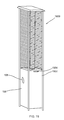
- FIG. 19 shows a rectangular shape flame heater.
- the number of parts in the rectangular shape flame heater is the same as the number of parts in the pyramid shape flame heater.
- the difference is that the upper plate, middle plate, and lower plate are the same size.
- the middle plate corner vertical connection tabs and the lower plate corner vertical connection tabs are at right angles respectively with the middle plate and the bottom plate.
- the upper protection guards, the lower protection guards, the side panels and the front door are rectangular in shape rather than trapezoidal in shape.
Landscapes
- Engineering & Computer Science (AREA)
- Chemical & Material Sciences (AREA)
- Combustion & Propulsion (AREA)
- Mechanical Engineering (AREA)
- General Engineering & Computer Science (AREA)
- Central Heating Systems (AREA)
Abstract
Description
Claims (25)
Priority Applications (1)
| Application Number | Priority Date | Filing Date | Title |
|---|---|---|---|
| US12/724,397 US8613277B2 (en) | 2009-03-17 | 2010-03-15 | Outdoor flame heater |
Applications Claiming Priority (3)
| Application Number | Priority Date | Filing Date | Title |
|---|---|---|---|
| US20260409P | 2009-03-17 | 2009-03-17 | |
| US20261809P | 2009-03-18 | 2009-03-18 | |
| US12/724,397 US8613277B2 (en) | 2009-03-17 | 2010-03-15 | Outdoor flame heater |
Publications (2)
| Publication Number | Publication Date |
|---|---|
| US20100236544A1 US20100236544A1 (en) | 2010-09-23 |
| US8613277B2 true US8613277B2 (en) | 2013-12-24 |
Family
ID=42736413
Family Applications (1)
| Application Number | Title | Priority Date | Filing Date |
|---|---|---|---|
| US12/724,397 Active 2032-10-24 US8613277B2 (en) | 2009-03-17 | 2010-03-15 | Outdoor flame heater |
Country Status (1)
| Country | Link |
|---|---|
| US (1) | US8613277B2 (en) |
Cited By (8)
| Publication number | Priority date | Publication date | Assignee | Title |
|---|---|---|---|---|
| US20130160756A1 (en) * | 2011-12-21 | 2013-06-27 | Allgreen Designs Co., Ltd. | Two-piece warming oven |
| US20150083116A1 (en) * | 2013-09-25 | 2015-03-26 | Ip Power Holdings Limited | Outdoor heating apparatus |
| US8991382B1 (en) * | 2011-01-05 | 2015-03-31 | Paul A. Mau | Fire pit that occupies a small space when disassembled |
| US20150354817A1 (en) * | 2014-06-10 | 2015-12-10 | Wet | Heater With Flame Display |
| US20170332779A1 (en) * | 2016-05-19 | 2017-11-23 | Bond Manufacturing Co Inc | Gas induction heater and gas induction heater and outdoor table connection system |
| US10330313B2 (en) | 2016-07-11 | 2019-06-25 | Well Traveled Imports INC | Twirling flame heater |
| USD906497S1 (en) | 2016-10-17 | 2020-12-29 | Well Traveled Imports, Inc. | Heater |
| US20210207810A1 (en) * | 2020-01-02 | 2021-07-08 | Sandra Vlock | Free-standing patio heater |
Families Citing this family (10)
| Publication number | Priority date | Publication date | Assignee | Title |
|---|---|---|---|---|
| TWM426739U (en) * | 2011-12-21 | 2012-04-11 | All Green Designs Co Ltd | Reflection type heat reservation furnace |
| CN102889634B (en) * | 2012-10-12 | 2015-03-25 | 江苏佳得顺热能设备有限公司 | Outdoor gas warmer |
| ES2490941B2 (en) * | 2013-02-04 | 2015-03-02 | Fundacion Prodintec | OUTDOOR STOVE FEEDED WITH BIOMASS PELLETS |
| US20140305427A1 (en) * | 2013-04-11 | 2014-10-16 | Hsin-Lien Liang | Combustion device for outdoor flame heater |
| CN105864837A (en) * | 2015-01-21 | 2016-08-17 | 王建平 | Outdoor gas appliance with audio-controlled flame |
| US10371386B2 (en) * | 2015-05-29 | 2019-08-06 | Bond Manufacturing Co., Inc. | Column heater with improved heat output |
| WO2019040782A1 (en) * | 2017-08-23 | 2019-02-28 | Mark Fuller | Fire under glass display |
| USD953499S1 (en) * | 2020-07-30 | 2022-05-31 | Canadian Tire Corporation Limited | Outdoor space heater |
| CA3102578A1 (en) | 2020-12-14 | 2022-06-14 | Hybrid Energies Alternatives Technologies Inc. | Convective outdoor heater |
| KR102729205B1 (en) * | 2022-11-07 | 2024-11-13 | 주식회사 극동주공 | Glass Patio Heater |
Citations (20)
| Publication number | Priority date | Publication date | Assignee | Title |
|---|---|---|---|---|
| US1536613A (en) * | 1924-03-20 | 1925-05-05 | Geneva Heater Company | Storage water heater |
| US2277302A (en) * | 1940-08-03 | 1942-03-24 | Joseph C Chenette | Portable hand truck |
| US3043116A (en) * | 1961-07-26 | 1962-07-10 | Leslie T Fuller | Refrigerator |
| US3851601A (en) * | 1973-02-09 | 1974-12-03 | J Davis | Display case stand |
| US4967916A (en) * | 1989-04-17 | 1990-11-06 | Hirsh Company | Post and joint construction |
| US6050177A (en) * | 1998-12-02 | 2000-04-18 | Lassig, Jr.; O. L. | Multi-fuel, fuel isolated cooker |
| US20030029439A1 (en) * | 2001-08-10 | 2003-02-13 | Uniflame Corporation | Knock-down dome cover for a patio heater |
| USD471622S1 (en) * | 2002-05-31 | 2003-03-11 | Uniflame Corporation | Portable heater |
| USD471967S1 (en) * | 2002-05-31 | 2003-03-18 | Uniflame Corporation | Patio heater |
| US20030056783A1 (en) * | 2001-08-22 | 2003-03-27 | Bossler Martin C. | Safety guard for patio heater |
| US20030085191A1 (en) * | 2001-11-07 | 2003-05-08 | Nagashimaya Co., Ltd., | Shelf unit |
| US6799660B1 (en) * | 2002-12-26 | 2004-10-05 | James R. Crawford | Step ladder device |
| US20060163438A1 (en) * | 2005-01-27 | 2006-07-27 | Wojotowicz David J | Post Coupler |
| US7175424B2 (en) * | 2003-06-24 | 2007-02-13 | Toby Frink | Indoor/outdoor patio heater fire sculpture |
| US20070034584A1 (en) * | 2005-08-12 | 2007-02-15 | Won-Gu Co., Ltd. | Assembling type sectional shelf structure |
| USD563537S1 (en) * | 2007-02-02 | 2008-03-04 | Desa Ip, Llc | Light post heater |
| USD567916S1 (en) * | 2007-02-02 | 2008-04-29 | Desa Ip, Llc | Light post heater |
| US20080152329A1 (en) * | 2006-12-22 | 2008-06-26 | Saunders Craig M | Portable collapsible radiant heater |
| US20110076627A1 (en) * | 2008-12-08 | 2011-03-31 | Diventura Louis | Heater apparatus |
| US20110162632A1 (en) * | 2009-12-08 | 2011-07-07 | Diventura Louis | Heater apparatus |
-
2010
- 2010-03-15 US US12/724,397 patent/US8613277B2/en active Active
Patent Citations (21)
| Publication number | Priority date | Publication date | Assignee | Title |
|---|---|---|---|---|
| US1536613A (en) * | 1924-03-20 | 1925-05-05 | Geneva Heater Company | Storage water heater |
| US2277302A (en) * | 1940-08-03 | 1942-03-24 | Joseph C Chenette | Portable hand truck |
| US3043116A (en) * | 1961-07-26 | 1962-07-10 | Leslie T Fuller | Refrigerator |
| US3851601A (en) * | 1973-02-09 | 1974-12-03 | J Davis | Display case stand |
| US4967916A (en) * | 1989-04-17 | 1990-11-06 | Hirsh Company | Post and joint construction |
| US6050177A (en) * | 1998-12-02 | 2000-04-18 | Lassig, Jr.; O. L. | Multi-fuel, fuel isolated cooker |
| US20030029439A1 (en) * | 2001-08-10 | 2003-02-13 | Uniflame Corporation | Knock-down dome cover for a patio heater |
| US6745759B2 (en) * | 2001-08-10 | 2004-06-08 | Cpd Associates, Inc. | Knock-down dome cover for a patio heater |
| US20030056783A1 (en) * | 2001-08-22 | 2003-03-27 | Bossler Martin C. | Safety guard for patio heater |
| US20030085191A1 (en) * | 2001-11-07 | 2003-05-08 | Nagashimaya Co., Ltd., | Shelf unit |
| USD471967S1 (en) * | 2002-05-31 | 2003-03-18 | Uniflame Corporation | Patio heater |
| USD471622S1 (en) * | 2002-05-31 | 2003-03-11 | Uniflame Corporation | Portable heater |
| US6799660B1 (en) * | 2002-12-26 | 2004-10-05 | James R. Crawford | Step ladder device |
| US7175424B2 (en) * | 2003-06-24 | 2007-02-13 | Toby Frink | Indoor/outdoor patio heater fire sculpture |
| US20060163438A1 (en) * | 2005-01-27 | 2006-07-27 | Wojotowicz David J | Post Coupler |
| US20070034584A1 (en) * | 2005-08-12 | 2007-02-15 | Won-Gu Co., Ltd. | Assembling type sectional shelf structure |
| US20080152329A1 (en) * | 2006-12-22 | 2008-06-26 | Saunders Craig M | Portable collapsible radiant heater |
| USD563537S1 (en) * | 2007-02-02 | 2008-03-04 | Desa Ip, Llc | Light post heater |
| USD567916S1 (en) * | 2007-02-02 | 2008-04-29 | Desa Ip, Llc | Light post heater |
| US20110076627A1 (en) * | 2008-12-08 | 2011-03-31 | Diventura Louis | Heater apparatus |
| US20110162632A1 (en) * | 2009-12-08 | 2011-07-07 | Diventura Louis | Heater apparatus |
Cited By (9)
| Publication number | Priority date | Publication date | Assignee | Title |
|---|---|---|---|---|
| US8991382B1 (en) * | 2011-01-05 | 2015-03-31 | Paul A. Mau | Fire pit that occupies a small space when disassembled |
| US20130160756A1 (en) * | 2011-12-21 | 2013-06-27 | Allgreen Designs Co., Ltd. | Two-piece warming oven |
| US20150083116A1 (en) * | 2013-09-25 | 2015-03-26 | Ip Power Holdings Limited | Outdoor heating apparatus |
| US20150354817A1 (en) * | 2014-06-10 | 2015-12-10 | Wet | Heater With Flame Display |
| US10101036B2 (en) * | 2014-06-10 | 2018-10-16 | Wet | Heater with flame display |
| US20170332779A1 (en) * | 2016-05-19 | 2017-11-23 | Bond Manufacturing Co Inc | Gas induction heater and gas induction heater and outdoor table connection system |
| US10330313B2 (en) | 2016-07-11 | 2019-06-25 | Well Traveled Imports INC | Twirling flame heater |
| USD906497S1 (en) | 2016-10-17 | 2020-12-29 | Well Traveled Imports, Inc. | Heater |
| US20210207810A1 (en) * | 2020-01-02 | 2021-07-08 | Sandra Vlock | Free-standing patio heater |
Also Published As
| Publication number | Publication date |
|---|---|
| US20100236544A1 (en) | 2010-09-23 |
Similar Documents
| Publication | Publication Date | Title |
|---|---|---|
| US8613277B2 (en) | Outdoor flame heater | |
| US9890951B2 (en) | All around radiation heating apparatus | |
| US9783216B2 (en) | Gas cylinder cart securable to gas grill | |
| AU2010227041B2 (en) | Grill handle with heat shield | |
| US20140069418A1 (en) | Collapsible camp stove | |
| US20110162632A1 (en) | Heater apparatus | |
| US20110076627A1 (en) | Heater apparatus | |
| US6044836A (en) | Artificial campfire | |
| AU2016203471A1 (en) | Column heater with improved heat output | |
| CN107062310A (en) | Gas kitchen ranges with integrated pot | |
| US6957649B1 (en) | Gas fired outdoor cooking apparatus | |
| US8459247B1 (en) | Outdoor cooking apparatus with removable heat shield | |
| EP1173714A1 (en) | Artificial campfire device | |
| US8776775B2 (en) | Single cavity radiant cooking apparatus | |
| US8001956B1 (en) | Outdoor cooking apparatus with removable heat shield | |
| US20140290642A1 (en) | Oven broil burner | |
| AU2006287848B2 (en) | Tank retainer | |
| JPH07286736A (en) | Outdoor disposing heater | |
| US9822982B2 (en) | Modular portable cooking system | |
| JP6787108B2 (en) | Hot water storage and hot water supply device | |
| US20180112882A1 (en) | Folding stove platform | |
| KR20160110852A (en) | stove having preventing device | |
| US5819719A (en) | Outdoor stove and stand | |
| US10551072B1 (en) | Strategic heat shield and burner assembly | |
| CN201100684Y (en) | A novel warm collection furnace |
Legal Events
| Date | Code | Title | Description |
|---|---|---|---|
| AS | Assignment |
Owner name: WELL TRAVELED LIVING, FLORIDA Free format text: ASSIGNMENT OF ASSIGNORS INTEREST;ASSIGNORS:HALL, EDWIN L., JR., MR.;TANNER, HAMPTON HOLLIS, MR.;REEL/FRAME:024083/0444 Effective date: 20100308 |
|
| STCF | Information on status: patent grant |
Free format text: PATENTED CASE |
|
| FPAY | Fee payment |
Year of fee payment: 4 |
|
| FEPP | Fee payment procedure |
Free format text: MAINTENANCE FEE REMINDER MAILED (ORIGINAL EVENT CODE: REM.); ENTITY STATUS OF PATENT OWNER: SMALL ENTITY |
|
| FEPP | Fee payment procedure |
Free format text: 7.5 YR SURCHARGE - LATE PMT W/IN 6 MO, SMALL ENTITY (ORIGINAL EVENT CODE: M2555); ENTITY STATUS OF PATENT OWNER: SMALL ENTITY |
|
| MAFP | Maintenance fee payment |
Free format text: PAYMENT OF MAINTENANCE FEE, 8TH YR, SMALL ENTITY (ORIGINAL EVENT CODE: M2552); ENTITY STATUS OF PATENT OWNER: SMALL ENTITY Year of fee payment: 8 |
|
| FEPP | Fee payment procedure |
Free format text: MAINTENANCE FEE REMINDER MAILED (ORIGINAL EVENT CODE: REM.); ENTITY STATUS OF PATENT OWNER: SMALL ENTITY |
|
| FEPP | Fee payment procedure |
Free format text: 11.5 YR SURCHARGE- LATE PMT W/IN 6 MO, SMALL ENTITY (ORIGINAL EVENT CODE: M2556); ENTITY STATUS OF PATENT OWNER: SMALL ENTITY |
|
| MAFP | Maintenance fee payment |
Free format text: PAYMENT OF MAINTENANCE FEE, 12TH YR, SMALL ENTITY (ORIGINAL EVENT CODE: M2553); ENTITY STATUS OF PATENT OWNER: SMALL ENTITY Year of fee payment: 12 |