US861237A - Cash-register. - Google Patents
Cash-register. Download PDFInfo
- Publication number
- US861237A US861237A US370240A US1907370240A US861237A US 861237 A US861237 A US 861237A US 370240 A US370240 A US 370240A US 1907370240 A US1907370240 A US 1907370240A US 861237 A US861237 A US 861237A
- Authority
- US
- United States
- Prior art keywords
- lever
- indicator
- yoke
- main
- coupling
- Prior art date
- Legal status (The legal status is an assumption and is not a legal conclusion. Google has not performed a legal analysis and makes no representation as to the accuracy of the status listed.)
- Expired - Lifetime
Links
Images

Classifications
-
- G—PHYSICS
- G06—COMPUTING OR CALCULATING; COUNTING
- G06C—DIGITAL COMPUTERS IN WHICH ALL THE COMPUTATION IS EFFECTED MECHANICALLY
- G06C7/00—Input mechanisms
- G06C7/10—Transfer mechanisms, e.g. transfer of a figure from a ten-key keyboard into the pin carriage
Definitions
- This invention relates to improvements in cash registers and indicators, and the present application is a division .of my prior application Serial No. 664,602, filed December 30, 18 97.
- the object of the invention set forth in the present application is to provide an improved form of indicator mechanism, or more particularly stated, to provide an improved mechanism for preventing what is known as the overthrow of the indicators of a cash register.
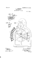
- Figure 1 represents an end elevation of the machine containing the devices above referred to;
- Fig. 1 represents an enlarged detailed perspective view of the indicator coupling slide;
- Fig. 1" represents a detailed view of part of the mechanism for latching the indicators in set position;
- Fig. 2 represents a vertical transverse section through the machine, and
- Fig. 2 represents a perspective view of one of the indicators and its actuating rack.
- 1 represents the main frame of the machine; 2 the depressible keys; 3 the reg.- istering wheels; 4 the indicating wheels; and 6 the opera-ting crank handle.
- the crank handle 6 is fast to a transverse crank shaft 8, which shaft carries two gear wheels 9, one on either side of the machine and mounted at opposite ends of the shaft 8.
- Each gear wheel 9 meshes with a. similar gear wheel 10 journaled on the frame 1, and each wheel 10 carries on one side near its periphery an anti friction roller 11 which is adapted to engage a curved operating arm or lever 12 journaled on the main shaft 13 of the machine.
- the lever 12 is rigidly connected to its respective end of the main operating yoke 14, this yoke comprising the two side arms connected by the horizontal cross bar extending across the back of the machine as is usual in machines of this type.
- crank handle 6 Upon the rotation of crank handle 6, in the direction shown by the arrow in Fig. 1, the rollers 11 are carried around upon their gear wheels 10 so as to permit the arms 12 to move upward and rearward, thereby permitting the main yoke to drop.
- the peculiar curved formation of the arms 12 permits of a partial movement of the rollers 11 while in contact with said arms without moving the latter, this structure being desirable in or: der to permit the handle 6 to move independently of the arms 12 after the movement of the latter is com pletcd, and thus operate the parts which must receive motion subsequent to the movement of said arms.
- a spring pressed retaining pawl 9" is mounted upon the main frame and engages the gear teethof the wheel 9 in such manner as to permit forward movement of the wheel but to prevent retrograde movement.
- the main yoke 14 is attached to the arm 14 which is likewise pivoted upon the main shaft 13.
- This arm 14 rests under and serves to lift the set of nested auxiliary operating yokes 56.
- These auxiliary yokes likewise have side arms pivoted upon the main shaft 13 similar to the side arms of the mafn yoke 14, and these yokes are nested one inside the other.
- Each of the aforesaid pawl carrying levers 83 has mounted upon it a spring pressed actuating pawl 15 which engagesthe teeth of the registering wheel 3.
- actuating pawl and awl carr 'in lever for each re isterin wheel and there is one registering wheel for each bank of keys.
- Each of the aforesaid auxiliary yokes 56 has fast to it and extending forwardly therefrom, a stepped segment 40.
- the steps of these segments are arranged tobe engaged by the inner ends of the stems of the depressible keys 2, and the steps are graduated so that when the auxiliary yoke 56 drops, and its segment moves upward and rearward, the extent of movement will vary according to whichever key is depressed; that is, if the uppermost key in the bank is depressed, the step frame and auxiliary yoke will move upward a space of one unit as the auxilary yoke drops, or if the lowermost key is do pressed, the step frame will be allowed to move upward a space of nine units.
- the auxiliary yokes 56 may also drop, and they drop to varying extents accord- I ing to the keys depressed in their corresponding banks.
- the keys may be utilized for values or for special dcsignations as is customary in machine of this type. If used for values then the register actuating pawls 15 are so arranged that they drop idly over the teeth of their pressed, means are provided for locking its correspoiuling step segment unless such key is depressed.
- a lrook arm 28 (see Fig. 2) is pivoted upon the shaft 32 and at its rearward end is formed with a hook engaging over a pin projecting from the downwardly extending portion of the segment 40. The arm 28 is fast to an upwardly extending arm 33 carrying a flat spring 34 engaging a pin 35.
- This pin is mounted on a toothed segment 36, and projects through a slot 33 formed in a detent plate 37, so that the pin 35 bears against spring 34.
- the toothed segment 36 isso placed that when apykoy is depressed, the key pin 37 projecting from the side of the key, presses against an inclined edge of one of the teeth of said segment and. lifts the segment. This of course lifts the pin 35 and causes the same to press against the spring 34 and thereby tend to rock forward the arm The rocking of this arm would tend to rock the hook arm upward so as to release its corresponding segment 40; but the segment is not immediately roles-sod but is released as follows.
- the aforesaid detent plate 37 formed on its outer periphery with the beveled noses also en gaging the key pins 37 and also formed with detent slots 37 An.
- arm 39 projects downward from this dctent plate 3'7, and extends opposite pin 30 projecting from the side of the hook arm 28.
- any key is depressed, its key pin 37 presses against the beveled nose of the detent plate and starts to lift said plate at the same time that it starts to lift the toothed segment plate as aforesaid, tends to rock the hook.
- each detent plate is provided with a'releasing bar 41.
- Each. bar 41 may be provided at its upper end with an enlargement or head 42 having an elongated slot 43 formed therein, through which slots the crank shaft 8 passes.
- Cams 44 may be provided on this shaft 8 to engage pins 45 projecting from the top of the heads 42 whereby to raise all of the bars 41 and thus release the depressed keys during the last portion of the movement of the crank handle.
- each auxiliary yoke 56 provided with a laterally projecting lug 61 in which is mounted an adjustable stop screw (52 for limiting the movement of its corresponding indicator setting lever 63.
- This indicator setting lever includes a forwardly extending arm 66 to which is pivotally connected at its forward end an indicator actuating rack bar 67.
- the upper end of this rack bar is formed with teeth engaging a pinion on the side of its corresponding indicator wheel 4.
- This rack bar and indicator is shown in detail in Fig. 2.
- the indicator stands in its normal zero position, the auxiliary yoke being in its normal raisedpositio'n, and suitable spring devices being utilized as is customary in machines of this type, to hold the indicator normally in this zero position with the reward arm 63 of its setting lever held upward against the set screw 62 of the auxiliary yoke.
- a rock frame 122 is provided, this frame comprising side arms and a horizontal cross bar, which horizontal bar engages .te'et-h formed on the rearward middle portions'of the indicator rack bars 67.
- the frame 122 is normally held rearward-and 'out of engagement with the indicator.
- lug" 61 of each auxiliary yoke bears upon the lever 63 and carries the same downward thereby carrying the actuating arm (56 upward to'an extent corresponding to the dropping movement of the auxiliary yoke. his of course moves the indicatoractuating rack bar and sets the indicator to show the value of the key which has been depressed. Then after the indicators have been set to their adjusted positions, the rock frame 122 is actuated to latch the i dicators in such position.
- the indicators of course Upon the restoration of the auxiliary yokes to normal zero position, the indicators of course remain latched in adjusted position while the log 61 retreats upward away from the indicator lever 63.
- the indicator lever 63 When the indicator is released at the next operation of the machine, of course the indicator lever 63 is allowed to return back to normal position against its lug 61, so as to again be set by the auxiliary yoke in case this sanie bank is operated.
- An inclined pin 58 projects downward from this coupling slide, and the coupling slide is formed with an elongated slot 59 and a guiding stem 59.
- a pin 60 mounted on the yoke 56 projects through the slot 59 to form a guide for the coupling slide, and the stem 59 projects through an apertured guide lug 56 also mounted upon the auxiliary yoke.
- the coiled spring 56 is mounted upon this stem 59 between said lug and the coupling slide.
- the side arms of the main operating lever or yoke 14 are connected by a transverse bar 69 which is so located in relation to the inclined pins 58 of the slides 57 as to engage said pin when the main yoke 'is raised. This results in moving the slide blocks rearward into the positions shown in Figs. 1 and 2.
- the coupling slides 57 are maintained inretracted position until an auxiliary yoke isstopped by its stepped segment coming in contact with tlie depressed key as previously described.
- the indicators and the auxiliary yokes normally stand uncoupled, but become coupled as an accompaniment to the advance or downward stroke of the main operating lever, and are again uncoupled upon the initial part of the return or upward stroke of the operating lever, and in fact the coupling takes place by reason of the main yoke separating from the auxiliary yoke when the latter is stopped and the main yoke goes onward, but these latter forms may be varied without departing from the spirit of the invention.
- a cash register the combination with a register of a series of operating levers.
- indicators operating devices for the indicators.
- 21 main operating lever for the register levers, movable locking devices between the registering lever-s and the Indicator operating devices, and arranged to be operated througnthe main operating lever upon its return stroke.
- a cash register the combination with a registering mechanism, of a series of auxiliary yokcs, a main yoke for operating the some, register operating devices actuated by the auxiliary yokcs, a series of indicators, operating levers for the indicators, coupling devices between the indicator levers and the auxiliary yokes, and means for actuating the coupling devices to uncouplc the parts upon the return stroke of the main yoke.
- a coupling device intermediate said ac touting lever and said indicator operating element, with a spring for forcing the coupling device into position to conple together said lever and element; and a controlling member connected with saidniain operating member and positioned to engage said coupling device and positively force .the same against its spring tension into uncoupling position on the return stroke oi. said operating member, but to be retracted from the coupling device to permit its spring to force it into couplin position during the advance stroke of the main operating member.
- a differentialiy movable auxiliary yoke a reciprocating main opersting lever therefor. an indicator, and an indicator operating lover, of a coupling device mounted on said auxiliary yoke and spring pressed into position to engage said indicator lever and couple the same to the yoke; and a bar connected to the main operating lever for positi'ely rctractlng said coupling device against its spring tension and out of coupling engagement upon the return stroke of the main operating lever, :said bar also being operated reversely as an accompaniment to the advance stroke of the main operating lever, to be withdrawn from contact with the coupling device and permit the latter to spring into engagement with the indicator lever to couple the latter to the said yoke.
- a coupling device mounted on said auxiliary yoke for coupling the latter to the indicator lever, said coupling device being in uncoupled position in the normal condition of the machine between transactions; a spring for moving the coupling device into engagement with the indicator lever to couple the latter to said yoke as an accompaniment to'the advance movement of the main operating lever, and a bar connected with said main operating lever and posi- 'tioned to engage the said coupling device and'positively retract the same'againjst its spring tension and into uncoupling position upon the return stroke of the main op erating lever.
- a couplingdevice for coupling together said auxiliary yoke and said indicator lever; and means connected with said mainoperating lever for causing the coupling device to assume its coupling position when the main operating lever retreats from the auxiliary yoke during the advance stroke-of the .main lever, and-causing the couplingdevice to assume its uncoupling position when the mainlever again engages the auxiliary yoke to return it to normal position upon the return stroke of the main lever.
- indicator operating levers 'of a coupling slide mounted on each of said auxiliary yokes; springs for moving said slides 'into position to couple the indicator levers to the auxiliary yokes; a transverse bar carried by said main yoke and positioned to engage arms extending from said coupling slides and hold said coupling slides normally retracted in uncoupling position until the main yoke retreats from the auxiliary yokes during the advance movement of the main yoke but said bar again engaging said arms to retract the 'coupling slides again 'intouncoupllng position when the
Landscapes
- Engineering & Computer Science (AREA)
- Physics & Mathematics (AREA)
- Computer Hardware Design (AREA)
- Computing Systems (AREA)
- General Physics & Mathematics (AREA)
- Theoretical Computer Science (AREA)
- Mechanical Control Devices (AREA)
Description
PATENTBD JULY 23, 1907.
J. H. MOOORMIGK.
CASH REGISTER.
APPLICATION FILED APB..26,1907.
Z SHEETS-SHEET 1.
PATENTED JULY 23. 1907.
2 SHBETS-BHEET 2.
J. H MOCORMIGK CASH REGISTER.
APPLIOATION TILED APR.26,1907.
UNITED STATES PATENT OFFICE.
IlOllN H. MCCORMICK, OF COLUMBUS, OHIO, ASSIGNOR TO THE NATIONAL CASH REGISTER COMPANY, CORPORATION OF OHIO, (INCORPORATED IN 1906.)
CASH-REGISTER.
Patented Jul 23, 1907.
Original application filed ec be 30, 1397, Serial No. 664,602. Divided and this application filed April 26, 1907.
' Serial No. 370,240.
To'xaZl whom'il may concern:
Be it known that 1, JOHN H. MCCORMICK, a citizen of the United States, residing at 60 Latta avenue, Oolumbus, in the county of-Franklin and State of Ohio have invented certain new'and useful Improvements in Cash-Registers, of which I declare the'following to be a full, clear, and exact description.
This invention relates to improvements in cash registers and indicators, and the present application is a division .of my prior application Serial No. 664,602, filed December 30, 18 97.
The object of the invention set forth in the present application is to provide an improved form of indicator mechanism, or more particularly stated, to provide an improved mechanism for preventing what is known as the overthrow of the indicators of a cash register.
The present improvements are shown and described more particularly with reference to that type of cash register and indicating machine in which there are a series of keys, which, when pressed in, set up stops to limit the movements of stepped segments, which stepped segments are compounded with a series of nested gravity yokes, so that the keys determine the extent of movement of the auxiliary yokes and segments; then for the purpose of supporting the nested auxiliary yokes, a main yoke is provided,'extending around the auxiliary yokes and arranged in conjunction with a main operating lever or member of some sort, by means of which the main yoke may be raised and lowered so to permit the lowering of the auxiliary yokes and their subsequent raising to home position; and thesev auxiliary yokes cooperate with concentrically pivoted pawl carrying arms for actuating the register wheels, and the same yokes also cooperate with indicator-operating devices for rotating roller indicators to display the amount of the transaction. Such a general type of machine is shown and described in Patent No. 570,141, issued to me on October 27, 1896, but in certain respects the machine shown in the present application differs from that shown in the patent just referred to, as, for example, in the said patent the operating of the registering wheels takes place upon the downward movement of the auxiliary yoke,whereas in the present machine the register wheels are actuated upon the return upward stroke of the auxiliary yokes toward home position.
1n machines of the general type shown in the present application, a restoration of the auxiliary yokes to normal elevated position is necessary in order to complete he operation of the machine, while at the same time the indication must endure, preferably until the next succeeding transaction; therefore it is necessary to provide a separable form of coupling between the indica tors and the auxiliary yokes, so that the yokes'can be .of the present invention to improve upon previously existing indicator mechanisms, so as effectually to prevent the overthrow of the indicators, that is, in advancemovement of the indicators beyond the positions which they should assume in order properly to indicate the exact transaction which has been entered upon the machine. v
With these and incidental objects in view, the invention consists in certain novel features of construction and combinationsof parts, the essential elements of which are set forth in appended claims and a preferred form of embodiment of which is hereinafter specifically described with reference to the drawings which accompany and form part of this specification.
01' said drawings: Figure 1 represents an end elevation of the machine containing the devices above referred to; Fig. 1 represents an enlarged detailed perspective view of the indicator coupling slide; Fig. 1" represents a detailed view of part of the mechanism for latching the indicators in set position; Fig. 2 represents a vertical transverse section through the machine, and Fig. 2 represents a perspective view of one of the indicators and its actuating rack.
Referring to these drawings, 1 represents the main frame of the machine; 2 the depressible keys; 3 the reg.- istering wheels; 4 the indicating wheels; and 6 the opera-ting crank handle. The crank handle 6 is fast to a transverse crank shaft 8, which shaft carries two gear wheels 9, one on either side of the machine and mounted at opposite ends of the shaft 8. Each gear wheel 9 meshes with a. similar gear wheel 10 journaled on the frame 1, and each wheel 10 carries on one side near its periphery an anti friction roller 11 which is adapted to engage a curved operating arm or lever 12 journaled on the main shaft 13 of the machine. The lever 12 is rigidly connected to its respective end of the main operating yoke 14, this yoke comprising the two side arms connected by the horizontal cross bar extending across the back of the machine as is usual in machines of this type. Upon the rotation of crank handle 6, in the direction shown by the arrow in Fig. 1, the rollers 11 are carried around upon their gear wheels 10 so as to permit the arms 12 to move upward and rearward, thereby permitting the main yoke to drop. The peculiar curved formation of the arms 12 permits of a partial movement of the rollers 11 while in contact with said arms without moving the latter, this structure being desirable in or: der to permit the handle 6 to move independently of the arms 12 after the movement of the latter is com pletcd, and thus operate the parts which must receive motion subsequent to the movement of said arms. This constructionhowever, does not form the subject matter of claims in the present case, and therefore no further reference to the same is necessary.
It will be obvious that the duplicate arrangement of the rollers 11 and arms 12 prevent any strain of the main yoke 14 in its raising movements. A spring pressed retaining pawl 9" is mounted upon the main frame and engages the gear teethof the wheel 9 in such manner as to permit forward movement of the wheel but to prevent retrograde movement. I
As shown in Fig. 1, the main yoke 14 is attached to the arm 14 which is likewise pivoted upon the main shaft 13. This arm 14 rests under and serves to lift the set of nested auxiliary operating yokes 56. These auxiliary yokes likewise have side arms pivoted upon the main shaft 13 similar to the side arms of the mafn yoke 14, and these yokes are nested one inside the other. For each auxiliary yoke there is a corresponding pawl carrying lever 83, each of said levers having a downwardly projecting curved arm 83 which rests upon its corresponding yoke 56. Each of the aforesaid pawl carrying levers 83 has mounted upon it a spring pressed actuating pawl 15 which engagesthe teeth of the registering wheel 3. Of course there is one actuating pawl and awl carr 'in lever for each re isterin wheel and there is one registering wheel for each bank of keys.
. Each of the aforesaid auxiliary yokes 56 has fast to it and extending forwardly therefrom, a stepped segment 40. The steps of these segments are arranged tobe engaged by the inner ends of the stems of the depressible keys 2, and the steps are graduated so that when the auxiliary yoke 56 drops, and its segment moves upward and rearward, the extent of movement will vary according to whichever key is depressed; that is, if the uppermost key in the bank is depressed, the step frame and auxiliary yoke will move upward a space of one unit as the auxilary yoke drops, or if the lowermost key is do pressed, the step frame will be allowed to move upward a space of nine units.
Upon the operation of the machine, when the main yoke 14 is allowed to drop as above described, carrying with. it the supporting arm 14, the auxiliary yokes 56 may also drop, and they drop to varying extents accord- I ing to the keys depressed in their corresponding banks.
The keys may be utilized for values or for special dcsignations as is customary in machine of this type. If used for values then the register actuating pawls 15 are so arranged that they drop idly over the teeth of their pressed, means are provided for locking its correspoiuling step segment unless such key is depressed. A lrook arm 28 (see Fig. 2) is pivoted upon the shaft 32 and at its rearward end is formed with a hook engaging over a pin projecting from the downwardly extending portion of the segment 40. The arm 28 is fast to an upwardly extending arm 33 carrying a flat spring 34 engaging a pin 35. This pin is mounted on a toothed segment 36, and projects through a slot 33 formed in a detent plate 37, so that the pin 35 bears against spring 34. The toothed segment 36 isso placed that when apykoy is depressed, the key pin 37 projecting from the side of the key, presses against an inclined edge of one of the teeth of said segment and. lifts the segment. This of course lifts the pin 35 and causes the same to press against the spring 34 and thereby tend to rock forward the arm The rocking of this arm would tend to rock the hook arm upward so as to release its corresponding segment 40; but the segment is not immediately roles-sod but is released as follows. Side by side with the toothed segment plate 36 is the aforesaid detent plate 37 formed on its outer periphery with the beveled noses also en gaging the key pins 37 and also formed with detent slots 37 An. arm 39 projects downward from this dctent plate 3'7, and extends opposite pin 30 projecting from the side of the hook arm 28. When any key is depressed, its key pin 37 presses against the beveled nose of the detent plate and starts to lift said plate at the same time that it starts to lift the toothed segment plate as aforesaid, tends to rock the hook. arm 28 upward, but the pin 30 is blocked by the arm 39 of the detent plate 37, which arm is also of course moving up with the de tent plate. When, however, the key pin 37 has been so far pushed inward that it is opposite the slot 37 of the detent plate 37, said plate then drops so that its hooked nose engages the'key pin and latches the key in depressed position. In such dropped position of the plate 37, the arm 39 is now out of the path of the pin 30, and the hook arm 28 can spring upward to release its corresponding segment. Therefore this segment may now rise and its attached auxiliary yoke 56 drop'when the main yoke drops, but it will he obyious that unless some key in the bank is depressed, the segnientrior that bank will not be unlocked and its auxiliary yoke will remain in normal upper position. One set of the aforedescribed blocking devices is provided for each of the separate banks. The result of .the above construction is that no segment is unlocked until the key in its corresponding bank is fully depressed to latched position.
In order to unla-tch the depressed keys by the operation of the machine, each detent plate is provided with a'releasing bar 41. Each. bar 41 may be provided at its upper end with an enlargement or head 42 having an elongated slot 43 formed therein, through which slots the crank shaft 8 passes. Cams 44 may be provided on this shaft 8 to engage pins 45 projecting from the top of the heads 42 whereby to raise all of the bars 41 and thus release the depressed keys during the last portion of the movement of the crank handle. This mechanism above described for releasing the stepped segments by the operation of the keys, and also for releasing the keys, is described in the aforesaid original application of which the present case is a division, and does not form the subject matter of claims herein. In aforesaid The pressure of the pin 35 against the spring 3t original application, other devices are described which form advantageous adjuncts to the mechanism hereinbel'ore described. For example, means are provided to prevent too rapid an operation 01 the main crank handle,
' and toinsure a full downward and upward movement of the main yoke; also a stop is provided for thecrank handle to limit its movement after one complete revolution; also devices are set forth for locking the register actuating pawls 15 to their-register wheels during the proper intervals for the purpose of securing absolutely accurate registration upon the register wheels; also devices for setting the register wheels back to zero; but such mechanisms will not be described herein, as the description herein is intended to bear mainly upon .the indicator devices. These indicating mechanisms will now be described. As shown in Fig. 2 each auxiliary yoke 56 provided with a laterally projecting lug 61 in which is mounted an adjustable stop screw (52 for limiting the movement of its corresponding indicator setting lever 63. This indicator setting lever includes a forwardly extending arm 66 to which is pivotally connected at its forward end an indicator actuating rack bar 67. The upper end of this rack bar is formed with teeth engaging a pinion on the side of its corresponding indicator wheel 4. This rack bar and indicator is shown in detail in Fig. 2. In the position of the parts shown in Fig. 2 the indicator stands in its normal zero position, the auxiliary yoke being in its normal raisedpositio'n, and suitable spring devices being utilized as is customary in machines of this type, to hold the indicator normally in this zero position with the reward arm 63 of its setting lever held upward against the set screw 62 of the auxiliary yoke.
It will be understood of course that there is one indicator with its connecting rack bar and actuator for each 01' the auxiliary yokes, that is for each of the banks of keys. In order to latch these indicators 4 in the positions to which they are adjusted, a rock frame 122 is provided, this frame comprising side arms and a horizontal cross bar, which horizontal bar engages .te'et-h formed on the rearward middle portions'of the indicator rack bars 67. The frame 122 is normally held rearward-and 'out of engagement with the indicator.
rack bars by means of a coiled spring 123, which connects it with the main frame, "and the rock frame is forced into engagement with the indicator 'liais' by means of a cam 124 mounted upon the crank shaft 8, this cam engaging any suitable portion of the rock frame 122 as clearly shown in Fig. 1. Thus upon the operation of the crank handle, the rotation of the earn 124 releases the rock frame 122 so that it springs away from the indicator rack bars to permit the rack bars to be restored to normal position, andafter the indicators have been set for the next transaction, the latching rockframe 122 is again cammed into engagement with the rack bars to latch the indicators in set position.
it will beapparent from the construction above de= scribed, that when any value keys 2 are depressed, and the machine operated byv turning the crank handle so as to causethe main yoketo oscillate down and up, the auxiliary yokes of the operated banks first drop undertheir own weight or under the influence of springs as is customary in machines of this type. These yokes of course drop todifi'erential positions dependent upon the valueof thekeys depressed. The "set screw 62 or the an amount in excess of the real amount.
; lug" 61 of each auxiliary yoke bears upon the lever 63 and carries the same downward thereby carrying the actuating arm (56 upward to'an extent corresponding to the dropping movement of the auxiliary yoke. his of course moves the indicatoractuating rack bar and sets the indicator to show the value of the key which has been depressed. Then after the indicators have been set to their adjusted positions, the rock frame 122 is actuated to latch the i dicators in such position.
Upon the restoration of the auxiliary yokes to normal zero position, the indicators of course remain latched in adjusted position while the log 61 retreats upward away from the indicator lever 63. When the indicator is released at the next operation of the machine, of course the indicator lever 63 is allowed to return back to normal position against its lug 61, so as to again be set by the auxiliary yoke in case this sanie bank is operated.
in case the auxiliary yokes are allowed to drop downward with considerable force, as mayordinarily happen in a quick operation of the machine, the momentum acquired by the indicator and its connecting parts would causetheindicator to overthrow at the same time when the auxiliary yoke is arrested by the depressed key. That is the indicator would be thrown beyond its proper position, and the lever 63 would be carried away from its lug (il. Therefore if the rock frame 122 were then to be actuated to latch the indicators they would be latched in wrong position showing prevent this overthrow oithe indicators the following mechanism is provided. Carried upon the side of each auxiliary yoke.56 is a spring pressed coupling slide 57 (see Fig. 2 & Fig. 1). An inclined pin 58 projects downward from this coupling slide, and the coupling slide is formed with an elongated slot 59 and a guiding stem 59. A pin 60 mounted on the yoke 56 projects through the slot 59 to form a guide for the coupling slide, and the stem 59 projects through an apertured guide lug 56 also mounted upon the auxiliary yoke. The coiled spring 56 is mounted upon this stem 59 between said lug and the coupling slide. I
The side arms of the main operating lever or yoke 14 are connected by a transverse bar 69 which is so located in relation to the inclined pins 58 of the slides 57 as to engage said pin when the main yoke 'is raised. This results in moving the slide blocks rearward into the positions shown in Figs. 1 and 2. When the main yoke 14 descends, with such of the auxiliary yoke s as have been released, the coupling slides 57 are maintained inretracted position until an auxiliary yoke isstopped by its stepped segment coming in contact with tlie depressed key as previously described. Upon the stopping of the auxiliary yoke, the continued downward movement of the main yoke of course instantly with- ;draws the transverse bars 69 from engagement with the pin 58 of this arrested auxiiary yoke. Therefore the spring 56" immediately forces the coupling slide 57 f0rward so that it springs under the indicator lever 63. This results in securely coupling the indicator to the. auxiliary yoke because the lever 63 is then held in between. thelug-GL and the couplingslide 57. 1 When the main yoke or operating lever l iret'urns toward normal position, it picks up the variousfauxiliary yokes in turn and assoon as the transverse bar 69 strikes the pins 58 of the coupling blocks 57 these coupling blocks are herefore to retracted rearward so that the indicator is uncoupled thereby from its auxiliary yoke and the indicator may remain latched in its adjusted position or set position While the auxiliary yoko is restored to normal upper position. Upon the next succeeding operation of the machine, when the previously adjusted indicator is released and allowed to return toward normal position, if its auxiliary yoke has already moved to its new set position and its coupling slide allowed to spring forward before the indicator lever 63 has returned to contact with its lug 61, then the beveled upper end of the lever 63 permits the lever to wipe by the spring pressed coupling block and thus again become coupled to the auxiliary yoke. Such might be the operation when a large registration of eight or nine units is followed by a filinlll registration of one or two units. The marked advantages of this form of indicator overthrow preventer will be apparent. During the downward reciprocation oi the main operating lover or main yoke, the coupling of the indicators to the auxiliary yokes or registering lovers obtains, and this coupling is not broken until the return stroke of the main operating element. The paramount importance of the accuracy of indication in cash registering machines has already been referred to above.
In machines of the particular type herein described, it has heretofore been suggested to couple and uncouple the indicator levers and the'auxiliary yokes, but the uncoupling took place during or toward the end of the downward reciprocation of the main operating lever.
. This of course fails 'to remedy the fatal overthrow defect at the very time when the indicators are most prone to overthrow, t. 6. when the weighted and spring impelled parts have acquired the greatest momentum. In the present invention, however, the parts are so organized that the coupling is maintained after the parts impelled by springs and weights have all completed their movements under such impulse and until a return movement or stroke of the actuating devices. In the particular form herein adopted, the indicators and the auxiliary yokes normally stand uncoupled, but become coupled as an accompaniment to the advance or downward stroke of the main operating lever, and are again uncoupled upon the initial part of the return or upward stroke of the operating lever, and in fact the coupling takes place by reason of the main yoke separating from the auxiliary yoke when the latter is stopped and the main yoke goes onward, but these latter forms may be varied without departing from the spirit of the invention. Therefore it may be stated that while the form of mechanism herein shown and described is admirably adapted to fulfil the objects primarily stated, it; is to be understood that it is not intended to confine the invention'to the one form of embodiment herein disclosed, forit is susceptible of embodiment in various forms all coming within the scope of the claims'which follow.
What is claimed is as follows.
1. In a cash register, the combination with a register of a series of operating levers. indicators, operating devices for the indicators. 21 main operating lever for the register levers, movable locking devices between the registering lever-s and the Indicator operating devices, and arranged to be operated througnthe main operating lever upon its return stroke.
2. in a cash register, the combination with a series oi. operating yokcs, of a lever for operating the same, a series of indicators, :1 series of indicator operating levers and coupling devices mounted on the operating yokes for coupling the lovers thereto, an operating device for reciprocating the main lever, and menus intermediate the main lover and the coupling devices for operating the latter upon the initial return movement oi said main lever.
.i. In :1 cash register, the combination with a series of operating yokcs, of an oscillatory lever for actuating the sumo, a series of indicators, indicator operating levers, and connections for setting the indicators upon the initial movements of the operating yokos, coupling devices on the operating yokes for coupling the indicator operating lovers thereto. and means intermediate the main operating lever and the coupling devices for operating the latter upoulhe return stroke of the lever and as it returns the operating ,vokes toward their normal positions.
4. In u cash register, the combination with a series of counting wheels. :1 series of operating yokos, a series of indicators, of aseries of indicator levers, and connections for setting the indicators upon the initial movements of the yokes, coupling devices mounted on the yokes for coupling the lovers thereto, register operating devices actuated upon the return movem nt of the yokes, a main operating lever for the yokes, and means intermediate the main lever and the coupling devices for actuating the latter upon the return movement of the lever.
5. In a cash register, the combination with a registering mechanism, of a series of auxiliary yokcs, a main yoke for operating the some, register operating devices actuated by the auxiliary yokcs, a series of indicators, operating levers for the indicators, coupling devices between the indicator levers and the auxiliary yokes, and means for actuating the coupling devices to uncouplc the parts upon the return stroke of the main yoke.
6. In a cash register, the combination with n difleren tially movable actuating lever, a reciprocating main open atiug member therefor, an indicator, and an indicator operating element, of coupling means intermediate s'aid actuating lover and said indicator operating element for coupling said lever and element together; and a controlling member connected with said main operating member and positioned to cause the operation of the coupling means in reverse directions upon the reverse movements of the no crating member for coupling and uncoupling the said indicater element and actuating lever.
7. In a cash register, the combination with a differentially movable actuating lover, a reciprocating main operating member therefor, an indicator, and an indicator operating element, of a coupling device intermediate said ac touting lever and said indicator operating element, with a spring for forcing the coupling device into position to conple together said lever and element; and a controlling member connected with saidniain operating member and positioned to engage said coupling device and positively force .the same against its spring tension into uncoupling position on the return stroke oi. said operating member, but to be retracted from the coupling device to permit its spring to force it into couplin position during the advance stroke of the main operating member.
8. In a cash register, the combination with a differentially movable auxiliary yoke, a reciprocating main operating lever therefor, an indicator, and an indicator op erating lever, of a coupling device intermediate said auxiliary yoke and said indicator lever, with a spring for forcing the coupling device into position to couple together said yoke and said indicator lever; and a bar connected with saidmsin operating lever for retracting said coupling device against its spring tension and out. of coupling position upon the return stroke of the main operating lever.
t). In a cash register, the combination with a differentialiy movable auxiliary yoke, a reciprocating main opersting lever therefor. an indicator, and an indicator operating lover, of a coupling device mounted on said auxiliary yoke and spring pressed into position to engage said indicator lever and couple the same to the yoke; and a bar connected to the main operating lever for positi'ely rctractlng said coupling device against its spring tension and out of coupling engagement upon the return stroke of the main operating lever, :said bar also being operated reversely as an accompaniment to the advance stroke of the main operating lever, to be withdrawn from contact with the coupling device and permit the latter to spring into engagement with the indicator lever to couple the latter to the said yoke.
10. In a cash register, the combination with a differenerating lever; and means connected with the main operat' ing lever for moving the coupling device into uncoupling position upon the initial return movement of the main operating lever. v
11. In a cash register, the combination with a differentially movable auxiliary yoke, a reciprocating main operating lever therefor, an indicator, and an indicatoroperating lever, of a. coupling device mounted on said auxiliary yoke for coupling the latter to the indicator lever, said coupling device being in uncoupled position in the normal condition of the machine between transactions; a spring for moving the coupling device into engagement with the indicator lever to couple the latter to said yoke as an accompaniment to'the advance movement of the main operating lever, and a bar connected with said main operating lever and posi- 'tioned to engage the said coupling device and'positively retract the same'againjst its spring tension and into uncoupling position upon the return stroke of the main op erating lever.
12. In a cash register, the combination with a difierentially movable auxiliary yoke, a reciprocating main operating lever therefor, an indicator, and an indicator operating lever, of a couplingdevice for coupling together said auxiliary yoke and said indicator lever; and means connected with said mainoperating lever for causing the coupling device to assume its coupling position when the main operating lever retreats from the auxiliary yoke during the advance stroke-of the .main lever, and-causing the couplingdevice to assume its uncoupling position when the mainlever again engages the auxiliary yoke to return it to normal position upon the return stroke of the main lever.
13. In a cash register,'the combination witha diflterem tially movable auxiliaryyoke, a reciprocating main operating lever therefor, an indicator, and an indicating operating lever, of a coupling device intermediate saidauxiliary yoke and said indicator lever, with a spring for forcing the coupling device into position to couple together said yoke and said indicator lever; and an extension directly con- .nected to said main operating lever and positioned to engage the coupling device, the construction being such that saidv extension is withdrawn from engagement with said coupling device when the main operating lever retreats from the auxiliary yoke during Che advance stroke of the main lever, but again engages and retracts the coupling device against its spring tension when the main lever again engages the-auxiliary yoke upon the return stroke of the main lever. I
14. In a cash register, the combination with a series of differentially movable auxiliary yokes, a reciprocating main operating 'yoke therefor, a series of indicators, and
indicator operating levers, of a coupling slide mounted on each of said auxiliary yokes; springs for moving said slides into position to couple the indicator levers to the auxiliary yokes; and a transverse bar connected with said main operating yokeand extending across the path of arms projecting from said coupling slides and operated by the main yoke to engage said arms upon the return stroke of the main yoke and retract'the coupling slides from coupling position. I
15. In a cash register, the combination with a series of differentially movable auxiliary yokes, a reciprocating main operating yoke therefor, a series of indicators, and
indicator operating levers, 'of a coupling slide mounted on each of said auxiliary yokes; springs for moving said slides 'into position to couple the indicator levers to the auxiliary yokes; a transverse bar carried by said main yoke and positioned to engage arms extending from said coupling slides and hold said coupling slides normally retracted in uncoupling position until the main yoke retreats from the auxiliary yokes during the advance movement of the main yoke but said bar again engaging said arms to retract the 'coupling slides again 'intouncoupllng position when the
Priority Applications (1)
| Application Number | Priority Date | Filing Date | Title |
|---|---|---|---|
| US370240A US861237A (en) | 1897-12-30 | 1907-04-25 | Cash-register. |
Applications Claiming Priority (2)
| Application Number | Priority Date | Filing Date | Title |
|---|---|---|---|
| US66460297A US1080646A (en) | 1897-12-30 | 1897-12-30 | Cash-register. |
| US370240A US861237A (en) | 1897-12-30 | 1907-04-25 | Cash-register. |
Publications (1)
| Publication Number | Publication Date |
|---|---|
| US861237A true US861237A (en) | 1907-07-23 |
Family
ID=2929690
Family Applications (1)
| Application Number | Title | Priority Date | Filing Date |
|---|---|---|---|
| US370240A Expired - Lifetime US861237A (en) | 1897-12-30 | 1907-04-25 | Cash-register. |
Country Status (1)
| Country | Link |
|---|---|
| US (1) | US861237A (en) |
-
1907
- 1907-04-25 US US370240A patent/US861237A/en not_active Expired - Lifetime
Similar Documents
| Publication | Publication Date | Title |
|---|---|---|
| US861237A (en) | Cash-register. | |
| US483946A (en) | roberts | |
| US773058A (en) | Cash-register. | |
| US523106A (en) | gleal | |
| US585468A (en) | Cash-register | |
| US589114A (en) | cash register | |
| US532762A (en) | carney | |
| US589245A (en) | carney | |
| US703639A (en) | Cash-register. | |
| US443024A (en) | Gash register and indicator | |
| US2598270A (en) | Indicating device on cash registers | |
| US680508A (en) | Cash-register. | |
| US1398576A (en) | Cash-register | |
| US573699A (en) | Fig-- ii | |
| US1183936A (en) | Total-printing cash-register. | |
| US468945A (en) | Cash-register | |
| US579604A (en) | pfeifer | |
| US474993A (en) | Cash register and indicator | |
| US687811A (en) | Cash-indicator. | |
| US484376A (en) | Ijvtejftor | |
| US755385A (en) | Cash-register. | |
| US773053A (en) | Cash-register. | |
| US793765A (en) | Cash-register. | |
| US773054A (en) | Cash-register. | |
| US622445A (en) | cleal |