US8612087B2 - Method for the detection of a component malfunction along the life of an internal combustion engine - Google Patents
Method for the detection of a component malfunction along the life of an internal combustion engine Download PDFInfo
- Publication number
- US8612087B2 US8612087B2 US13/102,770 US201113102770A US8612087B2 US 8612087 B2 US8612087 B2 US 8612087B2 US 201113102770 A US201113102770 A US 201113102770A US 8612087 B2 US8612087 B2 US 8612087B2
- Authority
- US
- United States
- Prior art keywords
- classifier
- component
- malfunction
- signals
- ecu
- Prior art date
- Legal status (The legal status is an assumption and is not a legal conclusion. Google has not performed a legal analysis and makes no representation as to the accuracy of the status listed.)
- Expired - Fee Related, expires
Links
Images


Classifications
-
- F—MECHANICAL ENGINEERING; LIGHTING; HEATING; WEAPONS; BLASTING
- F02—COMBUSTION ENGINES; HOT-GAS OR COMBUSTION-PRODUCT ENGINE PLANTS
- F02D—CONTROLLING COMBUSTION ENGINES
- F02D41/00—Electrical control of supply of combustible mixture or its constituents
- F02D41/02—Circuit arrangements for generating control signals
- F02D41/14—Introducing closed-loop corrections
- F02D41/1401—Introducing closed-loop corrections characterised by the control or regulation method
-
- F—MECHANICAL ENGINEERING; LIGHTING; HEATING; WEAPONS; BLASTING
- F02—COMBUSTION ENGINES; HOT-GAS OR COMBUSTION-PRODUCT ENGINE PLANTS
- F02D—CONTROLLING COMBUSTION ENGINES
- F02D41/00—Electrical control of supply of combustible mixture or its constituents
- F02D41/22—Safety or indicating devices for abnormal conditions
-
- F—MECHANICAL ENGINEERING; LIGHTING; HEATING; WEAPONS; BLASTING
- F02—COMBUSTION ENGINES; HOT-GAS OR COMBUSTION-PRODUCT ENGINE PLANTS
- F02D—CONTROLLING COMBUSTION ENGINES
- F02D2200/00—Input parameters for engine control
- F02D2200/02—Input parameters for engine control the parameters being related to the engine
- F02D2200/10—Parameters related to the engine output, e.g. engine torque or engine speed
- F02D2200/1015—Engines misfires
-
- F—MECHANICAL ENGINEERING; LIGHTING; HEATING; WEAPONS; BLASTING
- F02—COMBUSTION ENGINES; HOT-GAS OR COMBUSTION-PRODUCT ENGINE PLANTS
- F02D—CONTROLLING COMBUSTION ENGINES
- F02D41/00—Electrical control of supply of combustible mixture or its constituents
- F02D41/02—Circuit arrangements for generating control signals
- F02D41/14—Introducing closed-loop corrections
- F02D41/1497—With detection of the mechanical response of the engine
- F02D41/1498—With detection of the mechanical response of the engine measuring engine roughness
Definitions
- the technical field relates to a method for the detection of a component malfunction along the life of an Internal Combustion Engine (ICE).
- ICE Internal Combustion Engine
- misfire events have very negative effects on engine performance, on emissions values and could also cause damages on the catalyst.
- European and OBDII legislation require detecting misfire events causing excess emissions.
- misfire detection methods use the angular acceleration of the drive shaft in order to find a misfiring cylinder. As already well known these methods are not perfectly suitable since the angular acceleration of the drive shaft is influenced not only by misfire but also, for example, by the roughness of the road and by very sudden decelerations. Other detection methods use other signals or detailed mathematical models in order to estimate the misfire condition.
- At least a first object is to provide a method of detecting components malfunction or other undesirable events that takes into account possible variations of the components behavior during engine life and the associate components drift. At least a further object is to provide a malfunctioning detection method suitable for detecting misfire events and that takes into account possible variations during engine life of the phenomena associated and of the possible components drift. At least another object is to provide a malfunction detection method for components of an internal combustion engine that does not use complex devices and that takes advantage from the computational capabilities of the Electronic Control Unit (ECU) of the vehicle.
- ECU Electronic Control Unit
- An embodiment provides for a method for the detection of a component malfunction along the life of an Internal Combustion Engine, said engine, having at least a cylinder and being controlled by an Electronic Control Unit (ECU), the method comprising defining a pre-determined component malfunction classifier at the start of engine life and setting said classifier as active classifier, defining a validity condition for said active classifier, acquiring in real time a set of relevant signals relating to the operation of said component, feeding said signals to said active classifier in order to determine the occurrence or not of a malfunction of said component, and in case the validity condition of said actual classifier is not satisfied, defining a new classifier using the most recent relevant signals recorded by said ECU, and substituting the actual classifier with said new classifier.
- One of the advantages of the above method is that it allows to detect a malfunctioning of a component along the life of the engine, taking into account variations of behavior of the component due to drift of the same over time or due to any other cause.
- said pre-determined classifier is defined by means of a training session in order to train said classifier to distinguish the occurrence or not of a malfunction of said component, said training session comprising the input into said classifier of a plurality of signals subdivided in signals pertaining to a malfunction of said component and signals pertaining to a regular functioning of said component.
- the validity condition of said active classifier is evaluated as a function of the mean and of the variance values of the input signals pertaining to said component. This embodiment advantageously allows defining a validity condition for the active classifier.
- said validity condition is satisfied if the absolute value of the difference between the original mean of the signals pertaining to a regular functioning of said component and the mean of the signals calculated using the most recent relevant signals is lower than a minimum threshold or higher than a maximum threshold.
- said validity condition is satisfied if the absolute value of the difference between the original variance of the signals pertaining to a regular functioning of said component and the variance of the signals calculated using the most recent relevant signals is lower than a minimum threshold or higher than a maximum threshold.
- a search for a new classifier is performed continuously during the life of said engine. This embodiment allows precalculating a new classifier that can readily be substituted to the active classifier is the validity condition for the active classifier is not anymore satisfied.
- said component is a cylinder of said engine and said malfunction is a misfire.
- the method according to one of its aspects can be carried out with the help of a computer program comprising a program-code for carrying out all the steps of the method described above, and in the form of computer program product comprising the computer program.
- the computer program product can be embodied as a control apparatus for an internal combustion engine, comprising an Electronic Control Unit (ECU), a data carrier associated to the ECU, and the computer program stored in a data carrier, so that the control apparatus defines the embodiments described in the same way as the method. In this case, when the control apparatus executes the computer program all the steps of the method described above are carried out.
- ECU Electronic Control Unit
- the method according to a further embodiment can be also embodied as an electromagnetic signal, said signal being modulated to carry a sequence of data bits which represents a computer program to carry out all steps of the method.
- a still further aspect of the disclosure provides an internal combustion engine having at least a cylinder and comprising an Electronic Control Unit (ECU) specially arranged for carrying out the method claimed.
- ECU Electronic Control Unit
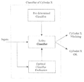
- FIG. 1 is a schematic diagram that illustrates a misfire detection logic for the method according to an embodiment
- FIG. 2 is a diagram that illustrates a training session for a generic engine cylinder according to an embodiment of the method
- FIG. 3 is a diagram that illustrates a real time classification for an engine having multiple cylinders according to an embodiment of the method
- FIG. 4 exemplifies different groups of samples plotted in a configuration space, according to an embodiment of the method.
- FIG. 5 illustrates a series of steps according to an embodiment of the method.
- Pattern recognition and more in general classification problems are solved, in literature, by different methods.
- Generically pattern recognition/classification methods work in the following way. First they extract from a training set of time-variant signals a set of information/parameters of different kinds related to the pattern recognition method chosen. This information is used to define the classifier. Secondly in real time, the pattern recognition method, using the classifier built in the first step, evaluates the samples in input in order to classify them.
- classification procedures permits to: (i) reduce the dimensions of the multi-dimensional space of the inputted samples, projecting them into directions that have the largest variance; (ii) create a classification rule where a pre-determined number of classes (or groups) is defined.
- the classes are determined minimizing the within-classes variance and maximizing the between-classes variance.
- the within-classes variance is the variance of the samples of the same class, while the between-classes variance is the variance between samples of different classes.
- the result looks like a projection matrix (in order to perform a real-time projection of the input samples into the new less-dimensional space) that has the property to separate in an optimal way the samples used as training set; and (iii) classify the inputted samples by means of the classification rule: in this way each sample is assigned to the most appropriate class, taking into account the classification rule provided by point (ii).
- the logic of an embodiment of the invention comprises three main steps training session: original classifier identification, real time classification between misfiring and not-misfiring cylinders, and evaluation of the drift of the system during engine life and identification of a new optimal classifier.
- a pre-determined classifier is built by means of a training dataset.
- the classifier identifies the optimal parameters for the misfire detection on each of the cylinders.
- a set of pre-calibrated parameters are evaluated identifying the pre-determined Classifier.
- the number of classes in the present case is two: misfiring cylinder and non-misfiring cylinder.
- a separate classifier is trained, using faulty and not faulty samples. The classifier is thus trained to distinguish if a specific cylinder is misfiring or not.
- FIG. 2 illustrates schematically the training logic for each cylinder “i” in a multi-cylinder engine. Specifically, a cylinder 20 and piston 40 group belonging to an Internal Combustion Engine (ICE) 10 is depicted and in which a fuel injector 30 injects a quantity of fuel into a combustion chamber 50 . As soon as the valve 60 closes, the fuel is ignited to start the combustion.
- ICE Internal Combustion Engine
- the input signals are a subset of the signals measured and calculated in the ECU.
- the choice of the signals used as inputs is driven by a preliminary analysis on the whole signals set recorded by ECU.
- the signal chosen may be:
- X2(t) Crankshaft acceleration signal
- Xn(t) Rail pressure signal
- a preferred choice is to use as inputs signals (or combinations of them) signals that, from common experience, are strictly related to the problem to be solved.
- the choice of the input signals may follow two rules: (i) samples that must be assigned to different classes (e.g.: misfire or no-misfire) must be well separated, and (ii) samples related to different misfiring cylinders must be well separated.
- a further example of input signals suitable for the detection of a cylinder misfire are: X(t): Lores Period (period between two combustion events, Y(t): Crankwheel Speed Gradient, and Z(t): Difference between consecutive 90° period of crankwheel signal. With these signals, the samples remain well-separated in different clusters.
- the classifier used is a pre-determined classifier.
- the new values of the same input signals used in the training session are considered by the classifier in order to distinguish between a misfiring and a non-misfiring cylinder.
- the space In order to classify the test samples the space must be divided into regions belonging to different classes.
- One possibility is to assign to the test sample the cluster with the smallest Mahalanobis distance. This, as other methods, permits to assign to each testing sample a class.
- FIG. 3 illustrates the functioning of the four classifiers for a 4-cylinder engine.
- a method that performs an optimal classifier evaluation is executed during the whole engine life. This method continuously searches for an optimal classifier, comparing the new classifier to the actual classifier used.
- the aim of this optimal classifier evaluation logic is to estimate the drift of the no-faulty class during engine life. In this way the parameters of the classifiers can be adjusted in order to permit to the real-time methods to distinguish better between a faulty sample from a no-faulty sample. This operation can be performed in different ways.
- a possible way is to calculate a time variant multidimensional mean value of the samples in input for each cylinder, considering obviously only the sub-space of the input signals.
- a proper logic on this mean and also on the samples multidimensional variance can lead to consider the drift during the engine life in order to have a sort of auto-adaptive learning of the best classifier for each cylinder, as exemplified in FIG. 4 .
- This approach constitutes an important improvement respect to more classical pattern recognition methods since this approach to misfire recognition using an auto-adaptive logic is able to consider the drifts during engine life.
- classifiers are calculated by means of statistical methods, therefore if means and variances of the clouds of samples changes, also the classes definition should be modified. In other words, during engine life, the inputs recorded by the ECU will be used as new training datasets. For this purpose, for example, the flow chart of FIG. 5 may be considered.
- a set of conditions is used to determine if the current classifier can still be used or, if due for example to components drifts over time, a new classifier must be substituted.
- the following means and variances of the signals pertaining to cylinder i are set for each ClassOk_i, namely the class related to non-misfiring samples of cylinder i.
- a Mean_New(ClassOk_i) parameter is set that represents the new mean of the non-misfiring samples calculated on the “n” last recorded samples and a Mean_Original(ClassOk_i) parameter is also set that represents the original mean value of the non-misfiring samples calculated in the training phase.
- a Var_New(ClassOk_i) parameter is set that represents the new variance of the non-misfiring samples calculated on the “n” last recorded samples and a Variance_Original(ClassOk_i) parameter is also set that represents the original variance value of the non-misfiring samples calculated in the training phase.
- equations 1 and 2 express the idea that a classifier that is not anymore valid due to components drift can be detected by the fact that the absolute value difference between the means or between the variances of the signals is greater than a minimum threshold and thus is not negligible and it is smaller than a maximum threshold and thus it is not relative to a non-misfiring cylinder.
- the mean and variance for each cylinder are calculated considering the behavior of the relative cylinder during an interval of time of some seconds.
- the sampling frequency may be adapted to the specific component monitoring with the proviso that the current state of electronic technology allows high sampling frequencies.
- the method as being exemplified with reference to cylinder misfire problems, but it can be readily applied to the detection of malfunction of other components of the engine.
Landscapes
- Engineering & Computer Science (AREA)
- Chemical & Material Sciences (AREA)
- Combustion & Propulsion (AREA)
- Mechanical Engineering (AREA)
- General Engineering & Computer Science (AREA)
- Combined Controls Of Internal Combustion Engines (AREA)
Abstract
Description
MinDriftMeanThreshold<|Mean_New(ClassOk— i)−Mean_Original(ClassOk— i)|<MaxDriftMeanThreshold. (Eq. 1)
MinDriftVarThreshold<|Var_New(ClassOk— i)−Var_Original(ClassOk— i)<|MaxDriftVarThreshold (Eq. 2)
Claims (10)
Applications Claiming Priority (2)
| Application Number | Priority Date | Filing Date | Title |
|---|---|---|---|
| GB1008499.4 | 2010-05-21 | ||
| GB1008499.4A GB2480495B (en) | 2010-05-21 | 2010-05-21 | Method for the detection of a component malfunction along the life of an internal combustion engine |
Publications (2)
| Publication Number | Publication Date |
|---|---|
| US20110288719A1 US20110288719A1 (en) | 2011-11-24 |
| US8612087B2 true US8612087B2 (en) | 2013-12-17 |
Family
ID=42341112
Family Applications (1)
| Application Number | Title | Priority Date | Filing Date |
|---|---|---|---|
| US13/102,770 Expired - Fee Related US8612087B2 (en) | 2010-05-21 | 2011-05-06 | Method for the detection of a component malfunction along the life of an internal combustion engine |
Country Status (4)
| Country | Link |
|---|---|
| US (1) | US8612087B2 (en) |
| CN (1) | CN102252853A (en) |
| GB (1) | GB2480495B (en) |
| RU (1) | RU2565937C2 (en) |
Cited By (1)
| Publication number | Priority date | Publication date | Assignee | Title |
|---|---|---|---|---|
| US20160160779A1 (en) * | 2014-12-08 | 2016-06-09 | Caterpillar Inc. | Prognostic Engine System and Method |
Families Citing this family (2)
| Publication number | Priority date | Publication date | Assignee | Title |
|---|---|---|---|---|
| US10598113B2 (en) * | 2016-08-31 | 2020-03-24 | Ford Global Technologies, Llc | Method for determining and applying an engine misfire threshold |
| CN113504143B (en) * | 2021-07-08 | 2024-09-17 | 潍柴动力股份有限公司 | Method and device for diagnosing valve seat wear |
Citations (12)
| Publication number | Priority date | Publication date | Assignee | Title |
|---|---|---|---|---|
| US5485374A (en) | 1992-06-03 | 1996-01-16 | Hitachi, Ltd. | Combustion-conditon diagnostic system and method for a multicylinder engine |
| US5869752A (en) * | 1990-12-10 | 1999-02-09 | Sensortech L.L.C. | Engine degradation detector |
| US6131444A (en) | 1998-09-15 | 2000-10-17 | Chrysler Corporation | Misfire detection using a dynamic neural network with output feedback |
| US6243641B1 (en) | 1995-06-07 | 2001-06-05 | Cummins Engine Company, Inc. | System and method for detecting engine cylinder misfire |
| US6273075B1 (en) * | 1999-04-13 | 2001-08-14 | Hyundai Motor Company | Method for detecting malfunction of car cylinder |
| US20030196481A1 (en) | 2002-04-17 | 2003-10-23 | Mitsubishi Denki Kabushiki Kaisha | Combustion state detection apparatus |
| US6978666B1 (en) * | 2004-09-08 | 2005-12-27 | Daimlerchrysler Corporation | Automatic calibration method for engine misfire detection system |
| US7032439B2 (en) * | 2003-09-11 | 2006-04-25 | Daimlerchrysler Corporation | Engine misfire detection using system identification technology |
| US20090229354A1 (en) * | 2006-06-21 | 2009-09-17 | Continental Automotive France | Method for detecting a misfire and corresponding device |
| US20090312941A1 (en) * | 2008-06-17 | 2009-12-17 | Gm Global Technology Operations, Inc. | Fuel system diagnostics by analyzing engine cylinder pressure signal and crankshaft speed signal |
| US7665558B2 (en) * | 2006-02-15 | 2010-02-23 | Toyota Jidosha Kabushiki Kaisha | Engine misfire detection apparatus, hybrid vehicle equipped with the same, and engine misfire detection method |
| US7991585B2 (en) * | 2008-10-01 | 2011-08-02 | Toyota Motor Engineering & Manufacturing North America, Inc. | Method and apparatus for three dimensional calibration of an on-board diagnostics system |
Family Cites Families (2)
| Publication number | Priority date | Publication date | Assignee | Title |
|---|---|---|---|---|
| IT1298944B1 (en) * | 1998-02-24 | 2000-02-07 | Automobili Lamborghini Spa | PROCEDURE FOR DETECTING FAILED EXPLOSION IN AN INTERNAL COMBUSTION ENGINE AND SYSTEM THAT PERFORMS THIS |
| JP4525538B2 (en) * | 2005-02-24 | 2010-08-18 | トヨタ自動車株式会社 | Misfire determination device and misfire determination method for internal combustion engine |
-
2010
- 2010-05-21 GB GB1008499.4A patent/GB2480495B/en not_active Expired - Fee Related
-
2011
- 2011-05-06 US US13/102,770 patent/US8612087B2/en not_active Expired - Fee Related
- 2011-05-10 RU RU2011118485/06A patent/RU2565937C2/en not_active IP Right Cessation
- 2011-05-23 CN CN2011101333554A patent/CN102252853A/en active Pending
Patent Citations (12)
| Publication number | Priority date | Publication date | Assignee | Title |
|---|---|---|---|---|
| US5869752A (en) * | 1990-12-10 | 1999-02-09 | Sensortech L.L.C. | Engine degradation detector |
| US5485374A (en) | 1992-06-03 | 1996-01-16 | Hitachi, Ltd. | Combustion-conditon diagnostic system and method for a multicylinder engine |
| US6243641B1 (en) | 1995-06-07 | 2001-06-05 | Cummins Engine Company, Inc. | System and method for detecting engine cylinder misfire |
| US6131444A (en) | 1998-09-15 | 2000-10-17 | Chrysler Corporation | Misfire detection using a dynamic neural network with output feedback |
| US6273075B1 (en) * | 1999-04-13 | 2001-08-14 | Hyundai Motor Company | Method for detecting malfunction of car cylinder |
| US20030196481A1 (en) | 2002-04-17 | 2003-10-23 | Mitsubishi Denki Kabushiki Kaisha | Combustion state detection apparatus |
| US7032439B2 (en) * | 2003-09-11 | 2006-04-25 | Daimlerchrysler Corporation | Engine misfire detection using system identification technology |
| US6978666B1 (en) * | 2004-09-08 | 2005-12-27 | Daimlerchrysler Corporation | Automatic calibration method for engine misfire detection system |
| US7665558B2 (en) * | 2006-02-15 | 2010-02-23 | Toyota Jidosha Kabushiki Kaisha | Engine misfire detection apparatus, hybrid vehicle equipped with the same, and engine misfire detection method |
| US20090229354A1 (en) * | 2006-06-21 | 2009-09-17 | Continental Automotive France | Method for detecting a misfire and corresponding device |
| US20090312941A1 (en) * | 2008-06-17 | 2009-12-17 | Gm Global Technology Operations, Inc. | Fuel system diagnostics by analyzing engine cylinder pressure signal and crankshaft speed signal |
| US7991585B2 (en) * | 2008-10-01 | 2011-08-02 | Toyota Motor Engineering & Manufacturing North America, Inc. | Method and apparatus for three dimensional calibration of an on-board diagnostics system |
Non-Patent Citations (1)
| Title |
|---|
| British Patent Office, British Search Report for British Application No. 1008499.4, dated Aug. 2, 2010. |
Cited By (1)
| Publication number | Priority date | Publication date | Assignee | Title |
|---|---|---|---|---|
| US20160160779A1 (en) * | 2014-12-08 | 2016-06-09 | Caterpillar Inc. | Prognostic Engine System and Method |
Also Published As
| Publication number | Publication date |
|---|---|
| RU2011118485A (en) | 2012-11-20 |
| GB201008499D0 (en) | 2010-07-07 |
| RU2565937C2 (en) | 2015-10-20 |
| US20110288719A1 (en) | 2011-11-24 |
| GB2480495A (en) | 2011-11-23 |
| GB2480495B (en) | 2017-08-23 |
| CN102252853A (en) | 2011-11-23 |
Similar Documents
| Publication | Publication Date | Title |
|---|---|---|
| US10818107B2 (en) | Engine analysis and diagnostic system | |
| US10816438B2 (en) | Machine learning for misfire detection in a dynamic firing level modulation controlled engine of a vehicle | |
| US10253716B2 (en) | Engine analysis and diagnostic system | |
| Sharma et al. | Misfire detection in an IC engine using vibration signal and decision tree algorithms | |
| US9074513B2 (en) | Non-intrusive exhaust gas sensor monitoring | |
| US10139314B2 (en) | Misfire detection device to detect misfire based on a frequency analysis of a rotation signal correlated with a rotational state of an internal combustion engine | |
| Jung et al. | Development of misfire detection algorithm using quantitative FDI performance analysis | |
| US9938918B2 (en) | Method and apparatus for evaluating abnormal combustion events of an internal combustion engine of a motor vehicle by regression calculation of a physical variable | |
| Chen et al. | Machine learning for misfire detection in a dynamic skip fire engine | |
| Devasenapati et al. | Misfire identification in a four-stroke four-cylinder petrol engine using decision tree | |
| US11346316B2 (en) | Ignition timing control device for internal combustion engine | |
| US8612087B2 (en) | Method for the detection of a component malfunction along the life of an internal combustion engine | |
| CN108691679B (en) | Method and system for controlling a propulsion system with sensor or actuator degradation | |
| CN113176739A (en) | Vehicle control device, vehicle control method, and non-transitory computer readable medium storing vehicle control program | |
| Pla et al. | An unsupervised machine learning technique to identify knock from a knock signal time-frequency analysis | |
| Canal et al. | Misfire detection in combustion engines using machine learning techniques | |
| CN114622990A (en) | Engine fire risk identification method, device, equipment and medium | |
| KR102163796B1 (en) | Misfire diagnosis method and device of Multi cylinder four-stroke engine | |
| Bhadane et al. | Misfire detection of automotive engines with convolutional neural network | |
| CN114962031B (en) | Method and system for detecting coking of pipeline of air inlet system of internal combustion engine and vehicle | |
| KR102300965B1 (en) | Misfire diagnosis method and device of Multi cylinder four-stroke engine | |
| Bahri et al. | Misfire detection in IC engine using Kstar algorithm | |
| Chatterjee et al. | Comparison of misfire detection technologies in spark-ignition engines for meeting on-board diagnostic regulation | |
| KR102202723B1 (en) | Misfire diagnosis method and device of Multi cylinder four-stroke engine | |
| Abdelati et al. | Enhanced engine misfire diagnosis through integration of vibration and acoustic emission signals using artificial neural networks |
Legal Events
| Date | Code | Title | Description |
|---|---|---|---|
| AS | Assignment |
Owner name: GM GLOBAL TECHNOLOGY OPERATIONS LLC, MICHIGAN Free format text: ASSIGNMENT OF ASSIGNORS INTEREST;ASSIGNOR:GIROTTO, MARCO;REEL/FRAME:026239/0423 Effective date: 20110504 |
|
| AS | Assignment |
Owner name: WILMINGTON TRUST COMPANY, DELAWARE Free format text: SECURITY AGREEMENT;ASSIGNOR:GM GLOBAL TECHNOLOGY OPERATIONS LLC;REEL/FRAME:028466/0870 Effective date: 20101027 |
|
| FEPP | Fee payment procedure |
Free format text: PAYOR NUMBER ASSIGNED (ORIGINAL EVENT CODE: ASPN); ENTITY STATUS OF PATENT OWNER: LARGE ENTITY |
|
| STCF | Information on status: patent grant |
Free format text: PATENTED CASE |
|
| AS | Assignment |
Owner name: GM GLOBAL TECHNOLOGY OPERATIONS LLC, MICHIGAN Free format text: RELEASE BY SECURED PARTY;ASSIGNOR:WILMINGTON TRUST COMPANY;REEL/FRAME:034186/0776 Effective date: 20141017 |
|
| FPAY | Fee payment |
Year of fee payment: 4 |
|
| MAFP | Maintenance fee payment |
Free format text: PAYMENT OF MAINTENANCE FEE, 8TH YEAR, LARGE ENTITY (ORIGINAL EVENT CODE: M1552); ENTITY STATUS OF PATENT OWNER: LARGE ENTITY Year of fee payment: 8 |
|
| FEPP | Fee payment procedure |
Free format text: MAINTENANCE FEE REMINDER MAILED (ORIGINAL EVENT CODE: REM.); ENTITY STATUS OF PATENT OWNER: LARGE ENTITY |
|
| LAPS | Lapse for failure to pay maintenance fees |
Free format text: PATENT EXPIRED FOR FAILURE TO PAY MAINTENANCE FEES (ORIGINAL EVENT CODE: EXP.); ENTITY STATUS OF PATENT OWNER: LARGE ENTITY |
|
| STCH | Information on status: patent discontinuation |
Free format text: PATENT EXPIRED DUE TO NONPAYMENT OF MAINTENANCE FEES UNDER 37 CFR 1.362 |
|
| FP | Lapsed due to failure to pay maintenance fee |
Effective date: 20251217 |