US8602976B2 - Endoscope - Google Patents
Endoscope Download PDFInfo
- Publication number
- US8602976B2 US8602976B2 US12/947,098 US94709810A US8602976B2 US 8602976 B2 US8602976 B2 US 8602976B2 US 94709810 A US94709810 A US 94709810A US 8602976 B2 US8602976 B2 US 8602976B2
- Authority
- US
- United States
- Prior art keywords
- pulley
- wire
- cover
- anchor element
- arm
- Prior art date
- Legal status (The legal status is an assumption and is not a legal conclusion. Google has not performed a legal analysis and makes no representation as to the accuracy of the status listed.)
- Expired - Fee Related, expires
Links
- 238000003780 insertion Methods 0.000 claims abstract description 13
- 230000037431 insertion Effects 0.000 claims abstract description 13
- 238000005452 bending Methods 0.000 description 13
- 238000000034 method Methods 0.000 description 3
- 238000003745 diagnosis Methods 0.000 description 2
- 238000002560 therapeutic procedure Methods 0.000 description 2
- 210000001072 colon Anatomy 0.000 description 1
- 238000010276 construction Methods 0.000 description 1
- 238000011109 contamination Methods 0.000 description 1
- 238000002788 crimping Methods 0.000 description 1
- 239000000463 material Substances 0.000 description 1
- 239000002184 metal Substances 0.000 description 1
- 229920003023 plastic Polymers 0.000 description 1
- 239000004033 plastic Substances 0.000 description 1
- 238000004659 sterilization and disinfection Methods 0.000 description 1
Images


Classifications
-
- A—HUMAN NECESSITIES
- A61—MEDICAL OR VETERINARY SCIENCE; HYGIENE
- A61B—DIAGNOSIS; SURGERY; IDENTIFICATION
- A61B1/00—Instruments for performing medical examinations of the interior of cavities or tubes of the body by visual or photographical inspection, e.g. endoscopes; Illuminating arrangements therefor
- A61B1/005—Flexible endoscopes
- A61B1/0051—Flexible endoscopes with controlled bending of insertion part
- A61B1/0052—Constructional details of control elements, e.g. handles
-
- A—HUMAN NECESSITIES
- A61—MEDICAL OR VETERINARY SCIENCE; HYGIENE
- A61B—DIAGNOSIS; SURGERY; IDENTIFICATION
- A61B1/00—Instruments for performing medical examinations of the interior of cavities or tubes of the body by visual or photographical inspection, e.g. endoscopes; Illuminating arrangements therefor
- A61B1/005—Flexible endoscopes
- A61B1/0051—Flexible endoscopes with controlled bending of insertion part
- A61B1/0057—Constructional details of force transmission elements, e.g. control wires
-
- Y—GENERAL TAGGING OF NEW TECHNOLOGICAL DEVELOPMENTS; GENERAL TAGGING OF CROSS-SECTIONAL TECHNOLOGIES SPANNING OVER SEVERAL SECTIONS OF THE IPC; TECHNICAL SUBJECTS COVERED BY FORMER USPC CROSS-REFERENCE ART COLLECTIONS [XRACs] AND DIGESTS
- Y10—TECHNICAL SUBJECTS COVERED BY FORMER USPC
- Y10T—TECHNICAL SUBJECTS COVERED BY FORMER US CLASSIFICATION
- Y10T29/00—Metal working
- Y10T29/49—Method of mechanical manufacture
- Y10T29/49826—Assembling or joining
Definitions
- the present invention relates to an endoscope and to a method of assembling an endoscope.
- Endoscopes containing control wires within Bowden cables that are pulled to steer a bending section at the distal end of the endoscope are well known.
- the loads in the controls wires are transferred to control wheels within a handle, and in a traditional endoscope this is achieved by a chain attached to the ends of the control wires passing over a sprocket attached to the control wheel.
- a problem with this arrangement is that it is expensive.
- an endoscope comprising a first pulley, an insertion portion having a steerable section and a control wire connecting said first pulley to said steerable section for controlling movement of said steerable section, wherein a portion of said control wire extends around said first pulley, and said endoscope further comprises a cover for controlling slack in the wire, said cover being mounted on said first pulley such that it is able to rotate with said first pulley.
- a method of assembling an endoscope comprising a pulley, an insertion portion having a steerable section and a control wife connecting said pulley to said steerable section for controlling movement of said steerable section, wherein said method comprises: locating a loop of said control wire around said pulley, and mounting a pulley cover over said loop of control wire and said pulley such that it is able to rotate with said pulley.
- FIG. 1 shows an endoscope 100
- FIG. 2 shows a wheel 104 attached to a pulley 209 of the endoscope 100 , and a wire 106 extending around the pulley;
- FIG. 3 shows a side view of the pulley 209 and wire 106 ;
- FIG. 4 shows the pulley 209 with a slack wire 106 B
- FIG. 5 shows the pulley 209 with the wire 106 when under tension
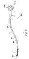
- FIG. 6 shows an endoscope 600 embodying the present invention
- FIG. 7 shows an exploded view of internal components of the endoscope handle 105 ;
- FIG. 8 shows the components of FIG. 7 after pulley covers 715 and 716 have been located on the pulley members 703 , 708 ;
- FIG. 9 shows a perspective view of the components previously shown in FIGS. 7 and 8 after assembly
- FIG. 10 shows a cross-sectional view of the components previously shown in FIGS. 7 and 8 after assembly
- FIG. 11 shows the pulley cover 715 located on the pulley 709 A.
- FIGS. 12A and 128 show two different perspective views of the pulley cover 12 .
- FIG. 1 A first figure.
- FIG. 1 A typical endoscope 100 usable for diagnosis or therapy of celiac cavities of the body is shown in FIG. 1 .
- the endoscope comprises insertion portion 101 having a steerable bending section 102 at one end.
- a distal cap 103 that contains a light source, camera and working channel through which instruments may be introduced during use.
- a handle 105 is provided at the opposite end of the insertion portion 101 .
- Two wheels 104 are provided on the handle 105 for controlling the bending section 102 .
- Control wires 106 extend along the length of the insertion portion 101 through Bowden cables.
- the Bowden outers terminate at the proximal end 107 of the bending section.
- the control wires 106 pass through the rings 108 and are fixed to the distal cap 103 .
- the insertion length 101 is fed into the celiac cavity, using the steerable bending section 102 to navigate.
- the image from the camera is used when guiding the bending section by use of the control wheels 104 on the handle 105 .
- the wheels control up, down, left and right movements by pulling on the control wires 106 that run through Bowden cables within the insertion length.
- FIG. 2 An arrangement where the wire 106 is wound around a pulley 209 attached to the wheel 104 is shown in FIG. 2 .
- the outer casing of the handle has been removed in FIG. 2 , along with a second pulley, for the purposes of clarity.
- An anchor element 210 is rigidly fixed to a mid-point of the wire 106 , and the anchor element resides within a hole 211 formed in the surface of the pulley, so that the wire is prevented from slipping around the pulley.
- the pulley 209 is shown in cross-section in FIG. 3 along with portions of the wire 106 in the vicinity of the pulley. As shown in FIG. 3 , a portion 106 A of the wire 106 is wrapped around the pulley for approximately 2.5 turns (900 degrees), while a second “up” portion 106 B and a third “down” portion 106 C of the wire 106 extend from the pulley 209 .
- the anchor element 210 and the portion 106 A of wire wrapped around the pulley 209 transfers the torque from the control wheel 104 to the wire 106 .
- a groove 312 is provided in the surface of the pulley 209 that extends around the pulley for approximately 90 degrees from each end of the hole 211 containing the anchor element 210 .
- the groove 312 extends along a part of a helical curve around the pulley to assist with the management of the wire 106 as it coils onto and uncoils from the pulley 209 .
- FIG. 4 shows the second “up” portion 106 B of the wire having become slack, and consequently it is tending to unwind from the pulley 209 . Because the wire is springy, when slack the radius of curvature of the wire increases more than the radius of the pulley and so the wire can move in unpredicted ways and later become tangled in the mechanism.
- FIG. 5 shows the third “down” portion 106 C wire 106 , which is tight, close to the pulley 209 , and not likely to tangle.
- FIG. 6 An endoscope 600 embodying the present invention is shown in FIG. 6 .
- the endoscope 600 like the endoscope 100 is usable for diagnosis or therapy of celiac cavities of the body and it shares many of its features with endoscope 100 .
- the endoscope 600 comprises an insertion portion 601 having a steerable bending section 602 at one end.
- a distal cap 103 that contains a light source, camera and working channel through which instruments may be introduced during use.
- a handle 605 is provided at the opposite end of the insertion portion 601 .
- Two wheels 604 A and 604 B are provided on the handle 605 that control the bending section 602 .
- Control wires (such as wire 606 , comprising portions 607 and 608 ) extend along the length of the insertion portion 601 through Bowden cables.
- the wheels 604 A and 604 B respectively control up-down, and left-right movements by pulling on the control wires.
- the handle 105 comprises a frame 701 defining bearings 702 A, 702 B and 702 C, which each have an internal bearing surface extending cylindrically around a common axis.
- the bearings 702 A, 702 B and 702 C are C-shaped, being open for almost 180 degrees about the common axis to allow other components of the handle to be clipped into place.
- the endoscope handle also comprises a first pulley member 703 defining a cylindrical bore 704 , a first pulley 709 A, a slotted head 706 , a middle shaft portion 705 A and an end shaft portion 705 B.
- the two shaft portions 705 A and 705 B are arranged either side of the pulley 709 A, and each have a cylindrical surface that is concentric with the bore 704 and has a diameter configured to be a good fit within the bearing 702 C, 702 B respectively.
- the first wheel 604 A has a hole 707 defining splines, and the slotted head 706 is configured to be a good fit within the hole 707 .
- the endoscope handle further comprises a second pulley member 708 defining a second pulley 709 B between an end shaft portion 720 and a central shaft 710 , which has a grooved portion 711 at its end.
- the central shaft 710 has a cylindrical outer surface configured to be a good fit within the bore 704 of the first pulley member 703 , such that the two pulley members are able to rotate freely with respect to each other about the aforementioned common axis.
- the end shaft portion 720 also has a cylindrical surface and it is configured to fit in the bearing 702 A.
- the second wheel 604 B has a hole 712 defining splines configured to be a good fit on the grooved end portion 711 of the second pulley member 708 .
- FIG. 7 Portions of the two control wires 606 and 714 are shown in FIG. 7 formed with loops configured to fit around the pulleys 709 A and 709 B respectively. (It should be understood that only portions of the wires in the vicinity of the pulleys are shown, and that the wires extend to the distal cap as indicated in FIG. 6 .)
- the wires 606 and 714 extend around the pulleys 709 A and 709 B for approximately three and a half turns.
- the wires are provided with an anchor element that slots into a suitably dimensioned hole in the surface of the pulley.
- each of the anchor elements comprises a metal object that is attached to the respective wire by crimping.
- the first pulley member 703 also defines a first cylindrical shoulder 751 between the first pulley 709 A and the end shaft portion 705 B.
- the second pulley member 708 also defines a second cylindrical shoulder 752 between the second pulley 709 B and the end shaft portion 720 .
- the handle also comprises pulley covers, 715 and 716 , which will be described in detail below.
- the pulley covers 715 and 716 are dimensioned to be a good fit over a respective one of the pulleys 709 A and 709 B when the wires 606 and 714 are located about the pulleys.
- the pulley covers 715 and 716 are provided with respective circular apertures 753 and 754 configured to receive the first and second cylindrical shoulders 751 , 752 respectively.
- the wire 606 is formed into loops that are then located about the pulley 709 A, before the pulley cover 715 is located over the pulley and wire assembly.
- the first cylindrical shoulder 751 of the pulley member 703 is located within the circular aperture 753 formed in the pulley cover 715 .
- wire 714 is formed into loops that are then located about the pulley 709 B.
- the second pulley cover 716 is then located over this second pulley and wire assembly, and the cylindrical shoulder 752 of the second pulley member 708 is located within the circular aperture 754 formed in the second pulley cover 716 .
- FIG. 7 The components of FIG. 7 are shown again in FIG. 8 after pulley covers have been located on the pulley members in this way.
- the central shaft 710 of the second pulley member 708 is then passed through the bore 704 of the first pulley member 703 and this assembly is clipped into the bearings 702 A, 702 B and 702 C of the frame 701 .
- the handle 604 A is then fitted to the slotted head 706 of the first pulley member 703 and the second handle 604 B is fitted to the grooved end portion 711 of the central shaft 710 .
- FIGS. 7 and 8 The components previously shown in FIGS. 7 and 8 are shown after assembly in the perspective view of FIG. 9 and cross-sectional view of FIG. 10 .
- Control wheel 604 B is used for ‘left/right’ control, and is connected to pulley 709 B covered by pulley cover 716 .
- Control wheel 604 A is used for up/down control and is connected to the pulley 709 A covered by pulley cover 715 .
- the pulley members are mounted to rotate within the frame 701 .
- the first pulley member 703 having shaft portions 705 B and 705 A mounted within the bearings 702 B and 702 C, while the second pulley member 708 has the end shaft portion 720 mounted within the bearing 702 A and the central shaft 710 mounted within the bore of the first pulley member 703 .
- the frame 701 , the two pulley members 703 and 708 , the pulley covers 715 and 716 and the wheels 604 A and 604 B are each moulded from a plastics material. Furthermore, the use of a chain and sprocket arrangement for connecting the wheels to the control wires is avoided by attaching the control wires directly to the pulleys. Consequently, the endoscope has a low cost construction allowing it to be used once and then disposed of, thereby avoiding contamination/sterilisation problems associated with the re-use of endoscopes.
- the pulley 709 A defines a hole 1101 configured to receive an anchor element 1102 that is rigidly attached to the wire 606 .
- a groove 1103 extends partly around the pulley from either end of the hole 1101 , so that a portion of the wire 606 on either side of the anchor element 1102 resides within the groove 1103 .
- the pulley cover 715 has a surface 1104 from which a side wall 1105 extends at right angles.
- the side wall comprises two substantially straight arms 1106 A and 1106 B joined by a curved central portion 1107 that extends approximately 180 degrees around a circle.
- the curved central portion of the wall has an inner surface configured to fit around the outside of the pulley 709 A and wire 606 .
- the pulley cover 715 fits over the pulley 709 A and can turn freely on the pulley. At the rear of the pulley in the vicinity of the anchor element 1003 the pulley cover 715 fits closely over the pulley 709 A, so constraining the wire 606 in the groove 1103 .
- the pulley is turned in the direction of the arrow 1108 the lower portion 608 of the wire 606 is placed in tension and is therefore straight and keeps in the pulley's groove 1103 .
- the slack side of the wire 606 that is the upper portion 607 , within the pulley cover 715 tends to expand (as described previously with respect to FIG. 4 ) and presses against the inside of the pulley cover.
- the pulley cover 715 located on the pulley 709 A constrains the wire 606 in the pulley groove 1103 and manages the slack wire (in the present example the upper portion 607 ) to prevent the tangling.
- the second pulley cover 716 operates on the wire 714 on the second pulley 709 B to perform a similar function.
- FIGS. 12 A and 12 B are identical to FIGS. 12 A and 12 B.
- the pulley cover 715 is shown in the perspective views of FIGS. 12A and 12B .
- the side wall 1105 which extends from the surface 1104 , has a curved central portion 1107 connecting two substantially straight arms 1106 A and 1106 B, which provide a force on the slack side of the wire 606 when the pulley 709 A is rotated.
- the arms ( 1106 A and 1106 B) are obscured by a flange 1201 and so the arms have been indicated in dotted outline in FIG. 12A .
- the arms 1106 A and 1106 B define a gap between which the wire extends from the pulley towards the steerable bending section 602 (shown in FIG. 6 ).
- the cover 715 also defines guide plates for maintaining the wire 606 in the correct planes.
- First and second, upper guide plates 1202 and 1203 extend from the arms 1106 A and 1106 B respectively, and a lower guide plate 1204 extends from the arm 1106 A.
- the first upper guide plate 1202 and lower guide plate 1204 are arranged to form a first slot 1205 such that the arm 1106 A forms the bottom of the slot.
- the second upper guide plate 1203 and the surface 1104 form a second slot 1206 such that the arm 1106 B forms the bottom of the slot.
- the wire 606 extends from the pulley 709 A through the slots 1205 and 1206 .
- the slots 1205 and 1206 are arranged to be at differing distances from the surface 1104 . This is because the portion of the wire that is wrapped around the pulley forms a helical shape, and so the wire leaves the pulley at differing positions along the aforementioned common axis.
Landscapes
- Health & Medical Sciences (AREA)
- Life Sciences & Earth Sciences (AREA)
- Surgery (AREA)
- Biomedical Technology (AREA)
- Medical Informatics (AREA)
- Optics & Photonics (AREA)
- Pathology (AREA)
- Radiology & Medical Imaging (AREA)
- Biophysics (AREA)
- Engineering & Computer Science (AREA)
- Physics & Mathematics (AREA)
- Heart & Thoracic Surgery (AREA)
- Nuclear Medicine, Radiotherapy & Molecular Imaging (AREA)
- Molecular Biology (AREA)
- Animal Behavior & Ethology (AREA)
- General Health & Medical Sciences (AREA)
- Public Health (AREA)
- Veterinary Medicine (AREA)
- Instruments For Viewing The Inside Of Hollow Bodies (AREA)
- Endoscopes (AREA)
Abstract
Description
Claims (18)
Applications Claiming Priority (6)
| Application Number | Priority Date | Filing Date | Title |
|---|---|---|---|
| GB0920116.1 | 2009-11-17 | ||
| GBGB0920116.1A GB0920116D0 (en) | 2009-11-17 | 2009-11-17 | Endoscope |
| GBGB0920116.1 | 2009-11-17 | ||
| GBGB1010334.9 | 2010-06-21 | ||
| GB1010334.9A GB2475364B (en) | 2009-11-17 | 2010-06-21 | Endoscope |
| GB1010334.9 | 2010-06-21 |
Publications (2)
| Publication Number | Publication Date |
|---|---|
| US20110118550A1 US20110118550A1 (en) | 2011-05-19 |
| US8602976B2 true US8602976B2 (en) | 2013-12-10 |
Family
ID=41509512
Family Applications (1)
| Application Number | Title | Priority Date | Filing Date |
|---|---|---|---|
| US12/947,098 Expired - Fee Related US8602976B2 (en) | 2009-11-17 | 2010-11-16 | Endoscope |
Country Status (2)
| Country | Link |
|---|---|
| US (1) | US8602976B2 (en) |
| GB (2) | GB0920116D0 (en) |
Families Citing this family (14)
| Publication number | Priority date | Publication date | Assignee | Title |
|---|---|---|---|---|
| US10307043B2 (en) * | 2013-03-15 | 2019-06-04 | Richard Rutgers | Endotracheal intubation devices |
| JP6329041B2 (en) * | 2014-09-17 | 2018-05-23 | Hoya株式会社 | Endoscope bending operation mechanism |
| ITUB20154977A1 (en) | 2015-10-16 | 2017-04-16 | Medical Microinstruments S R L | Medical instrument and method of manufacture of said medical instrument |
| US20190217034A1 (en) * | 2016-09-27 | 2019-07-18 | Andrew Maslow | Intubating endoscopic device |
| WO2018064185A1 (en) | 2016-09-27 | 2018-04-05 | Maslow Andrew | Intubating endoscopic device |
| EP4090223B1 (en) | 2020-01-15 | 2025-06-25 | Entellect Medical Holdings | Endoscope control handle with a steering assembly |
| FR3106269B1 (en) * | 2020-01-17 | 2022-04-29 | Axess Vision Tech | Handle with mechanism for controlling the flexion of the head of a medical endoscope |
| CN115397301A (en) * | 2020-03-30 | 2022-11-25 | 奥林巴斯株式会社 | Endoscope with a detachable handle |
| EP3903660A1 (en) * | 2020-04-30 | 2021-11-03 | Ambu A/S | A method of assembly of an endoscope control system |
| US12402782B2 (en) | 2020-04-30 | 2025-09-02 | Ambu A/S | Endoscope control system |
| DE102020121365A1 (en) | 2020-08-13 | 2022-02-17 | Ambu A/S | Endoscope based on the capstan principle |
| AU2021382738A1 (en) * | 2020-11-23 | 2023-07-13 | Adaptivendo Llc | Endoscope system |
| CN114403776A (en) * | 2021-12-07 | 2022-04-29 | 广州瑞派医疗器械有限责任公司 | Endoscope knob device, endoscope handle and endoscope |
| WO2025159075A1 (en) * | 2024-01-23 | 2025-07-31 | オリンパスメディカルシステムズ株式会社 | Insertion apparatus |
Citations (5)
| Publication number | Priority date | Publication date | Assignee | Title |
|---|---|---|---|---|
| US5007406A (en) | 1988-11-04 | 1991-04-16 | Asahi Kogaku Kogyo Kabushiki Kaisha | Bending control device of endoscope |
| US6491627B1 (en) | 1999-08-18 | 2002-12-10 | Fuji Photo Optical Co., Ltd. | Manipulation mechanism for an angle section of an endoscope |
| US20040015054A1 (en) * | 2002-07-05 | 2004-01-22 | Kazuhiko Hino | Bending control mechanism for endoscope |
| US20070010801A1 (en) * | 2005-06-22 | 2007-01-11 | Anna Chen | Medical device control system |
| US20100069834A1 (en) * | 2008-09-16 | 2010-03-18 | Jeffrey William Schultz | Catheter with adjustable deflection sensitivity |
-
2009
- 2009-11-17 GB GBGB0920116.1A patent/GB0920116D0/en not_active Ceased
-
2010
- 2010-06-21 GB GB1010334.9A patent/GB2475364B/en not_active Expired - Fee Related
- 2010-11-16 US US12/947,098 patent/US8602976B2/en not_active Expired - Fee Related
Patent Citations (5)
| Publication number | Priority date | Publication date | Assignee | Title |
|---|---|---|---|---|
| US5007406A (en) | 1988-11-04 | 1991-04-16 | Asahi Kogaku Kogyo Kabushiki Kaisha | Bending control device of endoscope |
| US6491627B1 (en) | 1999-08-18 | 2002-12-10 | Fuji Photo Optical Co., Ltd. | Manipulation mechanism for an angle section of an endoscope |
| US20040015054A1 (en) * | 2002-07-05 | 2004-01-22 | Kazuhiko Hino | Bending control mechanism for endoscope |
| US20070010801A1 (en) * | 2005-06-22 | 2007-01-11 | Anna Chen | Medical device control system |
| US20100069834A1 (en) * | 2008-09-16 | 2010-03-18 | Jeffrey William Schultz | Catheter with adjustable deflection sensitivity |
Non-Patent Citations (1)
| Title |
|---|
| Search Report for United Kingdom Patent Application No. GB1010334.9 dated Sep. 8, 2010. |
Also Published As
| Publication number | Publication date |
|---|---|
| GB201010334D0 (en) | 2010-08-04 |
| GB0920116D0 (en) | 2009-12-30 |
| GB2475364B (en) | 2012-03-21 |
| GB2475364A (en) | 2011-05-18 |
| US20110118550A1 (en) | 2011-05-19 |
Similar Documents
| Publication | Publication Date | Title |
|---|---|---|
| US8602976B2 (en) | Endoscope | |
| JP6329041B2 (en) | Endoscope bending operation mechanism | |
| US4483326A (en) | Curvature control mechanism in endoscopes | |
| JP5537748B1 (en) | Endoscope bending tube | |
| US11166627B2 (en) | Method for fixation of a wire portion of an endoscope, and an endoscope | |
| EP2564756B1 (en) | Endoscope | |
| US12471764B2 (en) | Endoscope with an articulated bending section body | |
| EP0447216A1 (en) | Bending device | |
| JP6043037B1 (en) | manipulator | |
| CN107249831B (en) | manipulator | |
| US20150079218A1 (en) | Optical fiber length adjuster | |
| CN119073875A (en) | A driving structure of a traction rope, an operating handle and an endoscope | |
| CN116194029A (en) | Endoscopes using the winch principle | |
| EP3415111A1 (en) | Manipulator system | |
| EP2832283A1 (en) | Insertion device and rotating tubular member | |
| US4074433A (en) | Intermaxillary tooth moving device | |
| JP2875583B2 (en) | Bending section for bending operation device | |
| US10918833B2 (en) | Modular handle assembly for a steerable catheter | |
| US12324566B2 (en) | Bending operation mechanism for endoscope and endoscope | |
| US20240389839A1 (en) | An endoscope | |
| CN115568807B (en) | Operation part for medical endoscope and endoscope | |
| JP2011120687A (en) | Insertion section of endoscope | |
| JP2864465B2 (en) | Angle for bending operation device | |
| US20250000348A1 (en) | Endoscope with wire pipes for guiding steering wires | |
| JPS6238411A (en) | Curving operation device for endoscope |
Legal Events
| Date | Code | Title | Description |
|---|---|---|---|
| AS | Assignment |
Owner name: SINGLE USE SURGICAL LIMITED OF BBIC, UNITED KINGDO Free format text: ASSIGNMENT OF ASSIGNORS INTEREST;ASSIGNOR:TULLEY, MATTHEW;REEL/FRAME:025369/0409 Effective date: 20101111 |
|
| AS | Assignment |
Owner name: SINGLE USE SURGICAL LIMITED, UNITED KINGDOM Free format text: CORRECTIVE ASSIGNMENT TO CORRECT NAME OF ASSIGNEE PREVIOUSLY RECORDED ON REEL 025369 FRAME 0409;ASSIGNOR:TULLEY, MATTHEW;REEL/FRAME:025641/0944 Effective date: 20101111 |
|
| STCF | Information on status: patent grant |
Free format text: PATENTED CASE |
|
| AS | Assignment |
Owner name: PELICAN FEMININE HEALTHCARE LIMITED, UNITED KINGDO Free format text: ASSIGNMENT OF ASSIGNORS INTEREST;ASSIGNOR:SINGLE USE SURGICAL LIMITED;REEL/FRAME:039070/0329 Effective date: 20160107 |
|
| FPAY | Fee payment |
Year of fee payment: 4 |
|
| SULP | Surcharge for late payment | ||
| AS | Assignment |
Owner name: EAKIN SURGICAL LIMITED, UNITED KINGDOM Free format text: CHANGE OF NAME;ASSIGNOR:PELICAN FEMININE HEALTHCARE LIMITED;REEL/FRAME:054341/0958 Effective date: 20201002 |
|
| FEPP | Fee payment procedure |
Free format text: MAINTENANCE FEE REMINDER MAILED (ORIGINAL EVENT CODE: REM.); ENTITY STATUS OF PATENT OWNER: SMALL ENTITY |
|
| LAPS | Lapse for failure to pay maintenance fees |
Free format text: PATENT EXPIRED FOR FAILURE TO PAY MAINTENANCE FEES (ORIGINAL EVENT CODE: EXP.); ENTITY STATUS OF PATENT OWNER: SMALL ENTITY |
|
| STCH | Information on status: patent discontinuation |
Free format text: PATENT EXPIRED DUE TO NONPAYMENT OF MAINTENANCE FEES UNDER 37 CFR 1.362 |
|
| FP | Lapsed due to failure to pay maintenance fee |
Effective date: 20211210 |