US8602714B2 - Structural profile rotator - Google Patents
Structural profile rotator Download PDFInfo
- Publication number
- US8602714B2 US8602714B2 US13/340,676 US201113340676A US8602714B2 US 8602714 B2 US8602714 B2 US 8602714B2 US 201113340676 A US201113340676 A US 201113340676A US 8602714 B2 US8602714 B2 US 8602714B2
- Authority
- US
- United States
- Prior art keywords
- hydraulic cylinder
- elongated
- elongated member
- rotate
- rotation
- Prior art date
- Legal status (The legal status is an assumption and is not a legal conclusion. Google has not performed a legal analysis and makes no representation as to the accuracy of the status listed.)
- Expired - Fee Related, expires
Links
Images


Classifications
-
- B—PERFORMING OPERATIONS; TRANSPORTING
- B23—MACHINE TOOLS; METAL-WORKING NOT OTHERWISE PROVIDED FOR
- B23Q—DETAILS, COMPONENTS, OR ACCESSORIES FOR MACHINE TOOLS, e.g. ARRANGEMENTS FOR COPYING OR CONTROLLING; MACHINE TOOLS IN GENERAL CHARACTERISED BY THE CONSTRUCTION OF PARTICULAR DETAILS OR COMPONENTS; COMBINATIONS OR ASSOCIATIONS OF METAL-WORKING MACHINES, NOT DIRECTED TO A PARTICULAR RESULT
- B23Q3/00—Devices holding, supporting, or positioning work or tools, of a kind normally removable from the machine
- B23Q3/18—Devices holding, supporting, or positioning work or tools, of a kind normally removable from the machine for positioning only
-
- B—PERFORMING OPERATIONS; TRANSPORTING
- B23—MACHINE TOOLS; METAL-WORKING NOT OTHERWISE PROVIDED FOR
- B23Q—DETAILS, COMPONENTS, OR ACCESSORIES FOR MACHINE TOOLS, e.g. ARRANGEMENTS FOR COPYING OR CONTROLLING; MACHINE TOOLS IN GENERAL CHARACTERISED BY THE CONSTRUCTION OF PARTICULAR DETAILS OR COMPONENTS; COMBINATIONS OR ASSOCIATIONS OF METAL-WORKING MACHINES, NOT DIRECTED TO A PARTICULAR RESULT
- B23Q1/00—Members which are comprised in the general build-up of a form of machine, particularly relatively large fixed members
- B23Q1/25—Movable or adjustable work or tool supports
- B23Q1/44—Movable or adjustable work or tool supports using particular mechanisms
- B23Q1/50—Movable or adjustable work or tool supports using particular mechanisms with rotating pairs only, the rotating pairs being the first two elements of the mechanism
- B23Q1/52—Movable or adjustable work or tool supports using particular mechanisms with rotating pairs only, the rotating pairs being the first two elements of the mechanism a single rotating pair
- B23Q1/525—Movable or adjustable work or tool supports using particular mechanisms with rotating pairs only, the rotating pairs being the first two elements of the mechanism a single rotating pair which is parallel to the working surface
Definitions
- This invention relates generally to rotating structural components, and more particularly, to an apparatus capable of quickly rotating and moving structural profiles on a single spindle beam drill line.
- a structural profile is a structural component used in constructing industrial buildings and other structures.
- Structural profiles consist of beams, angles, channels, square tubing, rectangular tubing, round tubing, T-sections, flat bars, and irregular shapes.
- Common materials used to create structural profiles comprise steel, reinforced concrete, wood, or other suitable metal alloys.
- CNC beam drill line is an indispensable way to quickly and easily drill holes and mill slots into beams, channels, and other structural profiles.
- CNC beam drill lines are typically equipped with feed conveyors and position sensors to move the element into position for drilling, as well as probing capability to determine the precise location where the hole or slot is to be cut.
- a structural profile is typically rotated on a single spindle drill line so that holes and slots can be placed on the various surfaces. While CNC beam drill lines can move the elements horizontally or vertically, rotational movement is not possible. For these circumstances, a crane or other type of machinery is commonly used to rotate the structural profiles along a single spindle drill line.
- U.S. Pat. No. 3,738,143 to Orris on Jun. 12, 1973 describes a beam rotating device used in rolling mill operation where two arms are tied together and used to rotate a steel beam. One arm supports a steal beam in a horizontal position and, on rotation of 90°, the beam is transferred to the second arm from the first. While this invention does use two arms to rotate a structural profile, the arms cannot move relative to each other, the device can only rotate profiles and cannot suspend them in desired positions, and the device cannot move the profile vertically and horizontally.
- U.S. Pat. No. 3,527,363 to Thatcher on Sep. 8, 1970 describes a structural profile rotating device where multiple support members at 90° angles are used to rotate the profiles from one position to another.
- the support members include guide rollers for loading the structural profiles and thereby rotating them about an axis. While this invention does use support members at 90° to rotate structural profiles, the support members are fixed, the device cannot move the profiles vertically and horizontally, and structural profiles cannot be loaded and unloaded onto drill lines using this device.
- the present device will provide a machine that can rotate a structural profile quickly and easily on a single spindle drill line without the use of a crane. This will allow a drill machine operator to rotate large and heavy structural profiles on a drill line and position them with the datum blocks in order to drill the different sides without the need for an overhead crane or other lifting device and without any additional labor to assist with manual flipping and positioning. This method will save manufacturers time and money, reduce operator fatigue, reduce overall complexity, and maximize safety. Furthermore, the present invention can rotate heavy structural profiles to a specific angle for saw cutting, flame cutting, fitting, welding, cleaning, grinding, priming, painting, drilling, punching, or even scribing on different surfaces.
- the profile rotator comprises an arm assembly having two elongated flat members, or blades, which lay flat along the same axis, and which are controlled by hydraulic cylinders.
- the unique rotation member allows one of the blades to rotate vertically while the other blade remains in its horizontal position, forming an ‘L’ shape.
- the shape of the rotation member allows the arms to uniquely rotate structural profiles while in the ‘L’ position without the use of complex positioning electronics. When the blade is rotated, a 90 degree angle is maintained between the blades. Both the first and second blades can rotate in this manner.
- a lift assembly moves the structural profiles vertically and a track assembly moves the structural profiles horizontally.
- a hose assembly connects all hydraulic cylinders to external power.
- a cover assembly protects the invention from exterior objects, dirt, metal shavings, or other harmful materials. Utilizing the lift assembly and track assembly, the arm assembly can lift, move, and rotate structural components on a drill line.
- FIG. 1 is a perspective view of the invention
- FIG. 2 is a side view of the invention exposing the arm and lift assemblies
- FIG. 3 is a top view of the invention
- FIG. 4 is an exploded perspective view of the invention
- FIG. 5 is an exploded side view of the invention
- FIG. 6 a is a side view of the arm assembly
- FIG. 6 b is a top view of the arm assembly
- FIG. 6 c is an exploded side view of the arm assembly
- FIG. 7 a is a side view of the arm assembly in one position
- FIG. 7 b is a side view of the arm assembly in an alternative position
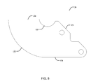
- FIG. 8 is a side view of the rotation member
- FIG. 9 is an exploded perspective view of the cover assembly
- FIG. 10 is a perspective view of the lift assembly
- FIG. 11 is an exploded perspective view of the track assembly.
- the present invention discloses a profile rotator 10 comprising an arm assembly 20 , a lift assembly 30 , a cover assembly 40 , a track assembly 50 , and a hose assembly 60 .
- the arm assembly 20 is used to rotate structural profiles clockwise and counterclockwise.
- the lift assembly 30 is adapted to move the structural profile vertically, while the track assembly 50 is adapted to move the structural profile horizontally.
- the hose assembly 60 connects the hydraulic lines 61 of the arm assembly 20 and lift assembly 30 to external power.
- the cover assembly 40 encapsulates the internal components 20 , 30 to protect them from outside objects.
- the arm assembly 20 comprises first and second elongated members 21 , 22 , or blades, each having a proximal 23 and distal 24 ends.
- a pivot member 25 is mutually connected to the proximal end 23 of each elongated member 21 , 22 .
- a rotation member 26 is fixedly attached to the second elongated member 22 and permits the blades 21 , 22 to rotate and hold their desired positions.
- a first hydraulic cylinder 27 is fixedly attached to the rotation member 26 on one end and fixedly attached to the first elongated member 21 on the other.
- a second hydraulic cylinder 28 is fixedly attached to the rotation member 26 on one end and fixedly attached to the cover assembly 40 on the other, the cover assembly 40 acting as a stationary anchor.
- the first and second hydraulic cylinders 27 , 28 are adapted to rotate the first and second elongated members 21 , 22 about the pivot member 25 by utilizing the shape of the rotation member 26 . More specifically, the first hydraulic cylinder 27 is adapted to rotate the first elongated member 21 relative to the second elongated member 22 , and the second hydraulic cylinder 28 is adapted to rotate the second elongated 22 member relative to the first elongated member 21 .
- the hydraulic cylinders 27 , 28 can create an angle in the range of 0° to 180° between the first and second elongated members 21 , 22 . Furthermore, the first and second hydraulic cylinders 27 , 28 are adapted to rotate the first and second elongated members 21 , 22 about the pivot member 25 while maintaining a rotation angle of 90 degrees.
- the rotation member 26 is used to maintain the appropriate angles without a complex electronic positioning system.
- the rotation member 26 can generally be described as a parallelogram, where one parallel side 121 is sloped as it should be, while the opposite side 122 instead comprises a convex curve.
- a groove 123 is positioned on a non-sloped side 124 and is adapted to rotate the rotation member 26 about the pivot member 25 .
- the first and second hydraulic cylinders 27 , 28 are attached to the sloped side 121 , with the first hydraulic cylinder 27 attached between the second hydraulic cylinder 28 and the groove 123 .
- the rotation member 26 is also rotated about said pivot member 25 as the blades 21 , 22 are rotated.
- the lift assembly 30 comprises two angled support members 31 that are rotatably attached to a rolling member 32 and the pivot member 25 .
- the third hydraulic cylinder 33 is fixedly attached to the rolling member 32 and cover assembly 40 at each end, thereby allowing the arm assembly 20 to move vertically by pushing and pulling the rolling member 32 along the track assembly 50 and altering the angle of the support members 31 .
- the cover assembly 40 comprises several panels 41 and encapsulates the rotation member 26 , first and second hydraulic units 27 , 28 , and lift assembly 30 . These units combine to protect the profile rotator 10 from exterior objects, dirt, metal shavings, or other harmful materials.
- the cover assembly 40 further comprises four alignment members 42 , each alignment member 42 having a means of movably securing the arm assembly 20 along the track assembly 50 .
- the arm assembly 20 is positioned above the cover assembly 40 and the hose assembly 60 extends from within the cover assembly 40 to the track assembly 50 .
- the first hydraulic cylinder 21 and third hydraulic cylinder 33 are fixedly attached to the cover assembly 40 .
- the cover assembly 40 comprises two chain members 34 which are fixedly attached to the chain 51 of the track assembly 50 .
- the track assembly 50 comprises two movement tracks 52 which allow the lift assembly 30 to move forward and backward, providing vertical force to the arm assembly 20 .
- the track assembly 50 further comprises two sprocket members 53 which are connected to a chain 51 . The sprocket members 53 can be rotated, thereby moving the chain members 34 , and consequently the lift cover 40 and arm assemblies 20 , horizontally along the track assembly 50 .
- the profile rotator 10 comprises three states: open ( FIG. 6 a ), forward ( FIG. 7 a ), and reverse ( FIG. 7 b ).
- the open state the first and second blades 21 , 22 are positioned horizontally, and an 180° angle exists between them.
- the first and second structural profiles along the drill line This position is also useful for positioning the profile rotator 10 for clockwise or counterclockwise rotation.
- the profile rotator 10 can enter either the forward state or the reverse state.
- the carefully calculated angles and positions of the rotation member 26 , pivot member 25 , and hydraulic cylinders 27 , 28 allow the blades 21 , 22 to rotate in a compact manner.
- the second blade 21 is rotated vertically and the first blade remains in its horizontal position.
- the first and second hydraulic cylinders 27 , 28 are extended and positioned horizontally, the resulting shape generally described as a forward ‘L.’
- the first blade 22 is rotated vertically and the second blade remains 21 remains in its horizontal position.
- the first hydraulic cylinder 27 is extended and positioned vertically while the second hydraulic cylinder 28 is contracted and positioned horizontally, the resulting shape generally described as a reverse ‘L.’
- the second hydraulic cylinder 28 has a fixed horizontal orientation, while the first hydraulic cylinder 27 has a variable orientation parallel to the first blade 21 .
- the first and second blades 21 , 22 can never rotate vertically at the same time.
- the profile rotator 10 can enter either the open state or the reverse state.
- the first blade 21 simply returns to its original horizontal position.
- both the first and second blades 21 , 22 rotate simultaneously until the first blade 21 rests horizontally and the second blade 22 rests vertically.
- the profile rotator second blade 22 simply returns to its original horizontal position.
- both the first and second blades 21 , 22 rotate simultaneously until the second blade 22 rests horizontally and the first blade 21 rests vertically.
- the structural profiles are rotated. If a clockwise rotation is desired, the structural profile is positioned on the first blade 21 with its edge, or flange, adjacent to the pivot member 25 of the arm assembly 20 . The profile rotator 10 will then enter the reverse state, resulting in the structural profile resting on the first blade 21 , but also positioned adjacent to the second blade 22 . The operator will then lift the structural profile using the lift assembly 30 and enter the forward state by rotating both blades 21 , 22 simultaneously. During the rotation, the structural profile will rest on both the first blade 21 and second blade 22 . Furthermore, the rotation can be suspended in any position in order to manipulate the structural profile at a desired angle. Once the profile rotator 10 enters the forward state, the operator will set the structural profile down using the lift assembly 30 . If a counterclockwise rotation is desired, the above method is repeated, but from a forward state to a reverse state.
- the profile rotator 10 can position itself along the drill line to ensure it is positioned properly. It can move horizontally in a forward and backward manner using the track assembly 50 . Furthermore, the profile rotator 10 can position itself vertically along the drill line. This is useful for positioning itself directly under the structural profile, and profile size is 40′′ (1,000 cm) and the maximum anticipated weight is 30,000 lbs (14,000 kg).
Landscapes
- Engineering & Computer Science (AREA)
- Mechanical Engineering (AREA)
- Earth Drilling (AREA)
Abstract
Description
Claims (15)
Priority Applications (1)
| Application Number | Priority Date | Filing Date | Title |
|---|---|---|---|
| US13/340,676 US8602714B2 (en) | 2011-01-12 | 2011-12-30 | Structural profile rotator |
Applications Claiming Priority (2)
| Application Number | Priority Date | Filing Date | Title |
|---|---|---|---|
| US201161432165P | 2011-01-12 | 2011-01-12 | |
| US13/340,676 US8602714B2 (en) | 2011-01-12 | 2011-12-30 | Structural profile rotator |
Publications (2)
| Publication Number | Publication Date |
|---|---|
| US20120177475A1 US20120177475A1 (en) | 2012-07-12 |
| US8602714B2 true US8602714B2 (en) | 2013-12-10 |
Family
ID=46455382
Family Applications (1)
| Application Number | Title | Priority Date | Filing Date |
|---|---|---|---|
| US13/340,676 Expired - Fee Related US8602714B2 (en) | 2011-01-12 | 2011-12-30 | Structural profile rotator |
Country Status (1)
| Country | Link |
|---|---|
| US (1) | US8602714B2 (en) |
Families Citing this family (3)
| Publication number | Priority date | Publication date | Assignee | Title |
|---|---|---|---|---|
| KR101451506B1 (en) * | 2013-04-17 | 2014-10-17 | 삼성전기주식회사 | Pcb transfer device in noncontact way |
| US9096388B2 (en) * | 2013-04-17 | 2015-08-04 | Geka Automation S.L. | Structural profile rotator, and rotator and conveyor assembly |
| CN203998007U (en) * | 2014-08-20 | 2014-12-10 | 纬创资通股份有限公司 | Turning device for adjusting the position of the chassis |
Citations (11)
| Publication number | Priority date | Publication date | Assignee | Title |
|---|---|---|---|---|
| US2940613A (en) * | 1957-11-04 | 1960-06-14 | Prentice Machine Works Inc | Sheet bundle handling apparatus |
| US3021018A (en) * | 1958-01-06 | 1962-02-13 | Homer D Paxson | Coil turning device |
| US3236396A (en) * | 1962-10-01 | 1966-02-22 | United Eng Foundry Co | Workpiece manipulator |
| US3319804A (en) * | 1965-01-21 | 1967-05-16 | Beatty Machine & Mfg Company | Beam handling apparatus |
| US3780882A (en) * | 1971-12-16 | 1973-12-25 | Moeller & Nuemann Gmbh | Plate turn-over mechanism |
| US6149376A (en) * | 1998-12-02 | 2000-11-21 | Amsted Industries Incorporated | Pipe moving method, apparatus and system |
| US6375178B1 (en) * | 2000-07-31 | 2002-04-23 | Genesis Systems Group, Ltd. | Dual cylinder work piece positioner |
| US6779787B2 (en) * | 2001-12-19 | 2004-08-24 | Kendro Laboratory Products, Inc. | Apparatus and method for rotating heavy objects |
| US20060180434A1 (en) * | 2005-02-16 | 2006-08-17 | Arnold Thomas A | Tray positioning device for stacking of product and method of use |
| US20100196133A1 (en) * | 2007-07-20 | 2010-08-05 | Gisbert Pass | Inspection system for rolled products and method for assessing the surface of rolled products of a rolling installation |
| US7985044B2 (en) * | 2006-07-19 | 2011-07-26 | Denson Co., Ltd. | Heavy article inversion device |
-
2011
- 2011-12-30 US US13/340,676 patent/US8602714B2/en not_active Expired - Fee Related
Patent Citations (11)
| Publication number | Priority date | Publication date | Assignee | Title |
|---|---|---|---|---|
| US2940613A (en) * | 1957-11-04 | 1960-06-14 | Prentice Machine Works Inc | Sheet bundle handling apparatus |
| US3021018A (en) * | 1958-01-06 | 1962-02-13 | Homer D Paxson | Coil turning device |
| US3236396A (en) * | 1962-10-01 | 1966-02-22 | United Eng Foundry Co | Workpiece manipulator |
| US3319804A (en) * | 1965-01-21 | 1967-05-16 | Beatty Machine & Mfg Company | Beam handling apparatus |
| US3780882A (en) * | 1971-12-16 | 1973-12-25 | Moeller & Nuemann Gmbh | Plate turn-over mechanism |
| US6149376A (en) * | 1998-12-02 | 2000-11-21 | Amsted Industries Incorporated | Pipe moving method, apparatus and system |
| US6375178B1 (en) * | 2000-07-31 | 2002-04-23 | Genesis Systems Group, Ltd. | Dual cylinder work piece positioner |
| US6779787B2 (en) * | 2001-12-19 | 2004-08-24 | Kendro Laboratory Products, Inc. | Apparatus and method for rotating heavy objects |
| US20060180434A1 (en) * | 2005-02-16 | 2006-08-17 | Arnold Thomas A | Tray positioning device for stacking of product and method of use |
| US7985044B2 (en) * | 2006-07-19 | 2011-07-26 | Denson Co., Ltd. | Heavy article inversion device |
| US20100196133A1 (en) * | 2007-07-20 | 2010-08-05 | Gisbert Pass | Inspection system for rolled products and method for assessing the surface of rolled products of a rolling installation |
Also Published As
| Publication number | Publication date |
|---|---|
| US20120177475A1 (en) | 2012-07-12 |
Similar Documents
| Publication | Publication Date | Title |
|---|---|---|
| US9744634B2 (en) | Support for workpieces | |
| JP7270542B2 (en) | Conveying apparatus, method and computer program product for loading into and out of at least one material machining unit | |
| US8734066B2 (en) | Hole saw tube notcher | |
| JP2016525947A5 (en) | ||
| JP5298873B2 (en) | Robot system | |
| US8602714B2 (en) | Structural profile rotator | |
| US20160207223A1 (en) | Material loading apparatus | |
| KR20200067156A (en) | Welding assembly, welding plant and method for welding | |
| US20080197093A1 (en) | Truss handling apparatus | |
| US9969077B2 (en) | Workpiece positioning apparatus, and method of using same | |
| JP2019181827A (en) | Fixing device for multi-axis robot, processing system, and fixing method of work piece | |
| JP6721916B2 (en) | Vehicle-mounted building material processing system and building material processing method | |
| KR102085231B1 (en) | Multi-axial welding equipment for welding free form surface | |
| US9561553B2 (en) | Transportable horizontal bandsaw assembly | |
| US8721254B1 (en) | Method for stacking beams | |
| CN102729059B (en) | Gantry machining centre and accessory head conveying device thereof | |
| US10450175B2 (en) | System for holding cabinets in place during installation | |
| US20240416439A1 (en) | Apparatus For Cutting Curved Wall Of Reactor Structure | |
| US8033777B2 (en) | Method and apparatus for transporting and moving load | |
| JP2020200593A (en) | Gripping device, gripping transportation device, and transportation/installation method using gripping device | |
| KR20210030671A (en) | Gantry crane apparatus | |
| KR102027257B1 (en) | Mobile Crane System | |
| EP2462046B1 (en) | Parts handling device | |
| WO2022167620A1 (en) | Remote operating device for the assembly/disassembly of a storage frame | |
| RU2459915C2 (en) | Method and device to lift steel frame |
Legal Events
| Date | Code | Title | Description |
|---|---|---|---|
| AS | Assignment |
Owner name: OCEAN MACHINERY, INC., A FLORIDA CORPORATION, FLOR Free format text: ASSIGNMENT OF ASSIGNORS INTEREST;ASSIGNOR:NGUYEN, THANH T;REEL/FRAME:027539/0005 Effective date: 20120112 |
|
| STCF | Information on status: patent grant |
Free format text: PATENTED CASE |
|
| FPAY | Fee payment |
Year of fee payment: 4 |
|
| FEPP | Fee payment procedure |
Free format text: MAINTENANCE FEE REMINDER MAILED (ORIGINAL EVENT CODE: REM.); ENTITY STATUS OF PATENT OWNER: MICROENTITY |
|
| FEPP | Fee payment procedure |
Free format text: ENTITY STATUS SET TO SMALL (ORIGINAL EVENT CODE: SMAL); ENTITY STATUS OF PATENT OWNER: SMALL ENTITY Free format text: 7.5 YR SURCHARGE - LATE PMT W/IN 6 MO, SMALL ENTITY (ORIGINAL EVENT CODE: M2555); ENTITY STATUS OF PATENT OWNER: SMALL ENTITY |
|
| MAFP | Maintenance fee payment |
Free format text: PAYMENT OF MAINTENANCE FEE, 8TH YR, SMALL ENTITY (ORIGINAL EVENT CODE: M2552); ENTITY STATUS OF PATENT OWNER: SMALL ENTITY Year of fee payment: 8 |
|
| FEPP | Fee payment procedure |
Free format text: MAINTENANCE FEE REMINDER MAILED (ORIGINAL EVENT CODE: REM.); ENTITY STATUS OF PATENT OWNER: SMALL ENTITY |
|
| LAPS | Lapse for failure to pay maintenance fees |
Free format text: PATENT EXPIRED FOR FAILURE TO PAY MAINTENANCE FEES (ORIGINAL EVENT CODE: EXP.); ENTITY STATUS OF PATENT OWNER: SMALL ENTITY |
|
| STCH | Information on status: patent discontinuation |
Free format text: PATENT EXPIRED DUE TO NONPAYMENT OF MAINTENANCE FEES UNDER 37 CFR 1.362 |
|
| FP | Lapsed due to failure to pay maintenance fee |
Effective date: 20251210 |