US8579095B2 - Clutch having a pre-clutch and a main clutch - Google Patents
Clutch having a pre-clutch and a main clutch Download PDFInfo
- Publication number
- US8579095B2 US8579095B2 US13/458,114 US201213458114A US8579095B2 US 8579095 B2 US8579095 B2 US 8579095B2 US 201213458114 A US201213458114 A US 201213458114A US 8579095 B2 US8579095 B2 US 8579095B2
- Authority
- US
- United States
- Prior art keywords
- clutch
- disc
- main
- ramp ring
- ramp
- Prior art date
- Legal status (The legal status is an assumption and is not a legal conclusion. Google has not performed a legal analysis and makes no representation as to the accuracy of the status listed.)
- Expired - Fee Related
Links
Images


Classifications
-
- F—MECHANICAL ENGINEERING; LIGHTING; HEATING; WEAPONS; BLASTING
- F16—ENGINEERING ELEMENTS AND UNITS; GENERAL MEASURES FOR PRODUCING AND MAINTAINING EFFECTIVE FUNCTIONING OF MACHINES OR INSTALLATIONS; THERMAL INSULATION IN GENERAL
- F16D—COUPLINGS FOR TRANSMITTING ROTATION; CLUTCHES; BRAKES
- F16D13/00—Friction clutches
- F16D13/04—Friction clutches with means for actuating or keeping engaged by a force derived at least partially from one of the shafts to be connected
-
- F—MECHANICAL ENGINEERING; LIGHTING; HEATING; WEAPONS; BLASTING
- F16—ENGINEERING ELEMENTS AND UNITS; GENERAL MEASURES FOR PRODUCING AND MAINTAINING EFFECTIVE FUNCTIONING OF MACHINES OR INSTALLATIONS; THERMAL INSULATION IN GENERAL
- F16D—COUPLINGS FOR TRANSMITTING ROTATION; CLUTCHES; BRAKES
- F16D13/00—Friction clutches
- F16D13/22—Friction clutches with axially-movable clutching members
- F16D13/38—Friction clutches with axially-movable clutching members with flat clutching surfaces, e.g. discs
- F16D13/52—Clutches with multiple lamellae ; Clutches in which three or more axially moveable members are fixed alternately to the shafts to be coupled and are pressed from one side towards an axially-located member
- F16D13/54—Clutches with multiple lamellae ; Clutches in which three or more axially moveable members are fixed alternately to the shafts to be coupled and are pressed from one side towards an axially-located member with means for increasing the effective force between the actuating sleeve or equivalent member and the pressure member
Definitions
- the invention relates to a clutch having a pre-clutch and a main clutch.
- a clutch is known in the prior art from European Patent No. 1685332 B1, having a pre-clutch and a main clutch.
- the pre-clutch can be arranged between the main clutch and the actuating element of the pre-clutch. Furthermore, a radial outside area of the clamping means of the pre-clutch is effectively connected to a clutch hub of the pre-clutch, and the radial middle area of the clamping means is effectively connected to a disc or counter-disc of the pre-clutch. In the area lying radially to the inside, the clamping means has a contact area for the actuating element. This arrangement reduces the inertia of the pre-clutch. The dynamics of the clutch are therefore significantly improved.
- a clutch basket of the pre-clutch is rotatably mounted by a bearing to the clutch hub of the pre-clutch.
- a clutch hub of the main clutch is connected via a torque damper, especially via spring means, to the clutch hub of the pre-clutch.
- a clutch hub of the pre-clutch is mounted via a second bearing to a clutch basket of the main clutch.
- a second clamping means is provided that clamps the disc and counter-disc of the pre-clutch against each other.
- a third clamping means is provided that pretensions the main clutch in the direction of engagement.
- means for example, a tension spring, pressure spring, rubber pressure piece and/or a damper, are provided that improve the effective connection between the main clutch and the pre-clutch.
- these means can dampen vibration or grabbing by the pre-clutch. This feature is independent from the design of the clutch and can be used in various embodiments.
- the first and/or second bearing has means for generating basic friction, where the means are preferably designed in the form of a friction disc and/or in the form of a spring means for adjusting the friction of the bearing. For example, this can dampen the vibration of the pre-clutch.
- This feature is independent from the design of the clutch and can be used in various embodiments.
- the main clutch is effectively connected via a torque damper, such as spring means, to the pre-clutch.
- FIG. 1 shows a schematic representation of a first clutch embodiment
- FIG. 2 displays representations of slopes of ramp surfaces of a ramp device
- FIG. 3 shows a perspective partial cross-sectional view of the clutch illustrated in FIG. 1 ;
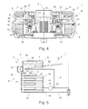
- FIG. 4 shows a cross-sectional view through the middle of the clutch from FIG. 3 ;
- FIG. 5 shows a schematic representation of a second clutch embodiment
- FIG. 6 shows a schematic representation of a third clutch embodiment
- FIG. 7 shows a schematic representation of a fourth clutch embodiment
- FIG. 8 shows a schematic representation of a fifth clutch embodiment
- FIG. 9 shows a schematic representation of a sixth clutch embodiment
- FIG. 10 shows a schematic representation of a seventh clutch embodiment
- FIG. 11 shows a schematic representation of an eighth clutch embodiment.
- FIG. 1 shows a schematic representation of a partial section of one half of clutch 1 . arranged around rotational axis 2 having pre-clutch 3 and main clutch 4 .
- Clutch 1 is a wet clutch.
- Pre-clutch 3 and the main clutch are effectively connected to each other by means of effective connection means 12 .
- first clutch basket 5 of pre-clutch 3 first disc 6 is suspended non-rotatably and slightly shiftable axially along rotational axis 2 , and, for example, includes drivers or friction discs coated with friction material. Only first disc 6 is shown in the portrayed embodiment. Plurality of first discs 6 can also be provided.
- each first disc 6 is assigned first counter-disc 7 , where first counter-discs 7 are accommodated non-rotatably and axially movable along rotational axis 2 in first clutch hub 8 of pre-clutch 3 .
- first clutch hub 8 is connected to transmission input shaft 15 .
- First disc 6 is a driver disc, and the first counter-disc is a disc.
- First counter-discs 7 are, for example, made of steel.
- First clutch hub 8 has outer and inner plates 81 , 82 , between which first disc 6 and first counter-disc 7 are arranged. Furthermore, clamping means 10 , for example, in the form of a disc spring that compresses first disc 6 and first counter-disc 7 , and therefore, connects first clutch basket 5 to first clutch hub 8 non-rotatably, thereby engaging clutch 3 .
- First clutch basket 5 is rotatably mounted by means of bearing 13 to first clutch hub 8 . When pre-clutch 3 is disengaged, first clutch basket 5 can rotate in relation to first clutch hub 8 .
- Clamping means 10 rests against inner plate 82 in radially outside area 101 .
- first clamping means 10 lies against the bottom side of first counter-disc 7 .
- clamping means 10 has another contact area 102 for an effective connection to an actuating element.
- First clutch basket 5 has first ramp ring 11 that is assigned to second ramp ring 21 of main clutch 4 .
- First ramp ring 11 is, for example, part of a connecting piece of first clutch basket 5 that is guided to bearing 13 .
- Transmission element 22 is formed between first ramp ring 11 and second ramp ring 21 , for example, in the shape of a ball.
- First ramp ring 11 , transmission element 22 , and second ramp ring 21 represent effective connection means 12 between pre-clutch 3 and main clutch 4 .
- Second ramp ring 21 can be designed as part of a cover of main clutch 4 .
- Second ramp ring 21 is fastened non-rotatably and slightly axially shiftable along rotational axis 2 in second clutch basket 16 of main clutch 4 .
- Main clutch 4 has two discs 17 that are suspended non-rotatably and slightly axially shiftable along rotational axis 2 in second clutch basket 16 .
- main clutch 4 has second clutch hub 18 in which two counter-discs 19 are suspended non-rotatably and slightly axially shiftable along rotational axis 2 .
- Second discs 17 and second counter-discs 19 are arranged in alternate layers as shown in FIG. 1 .
- Second clutch hub 18 is connected via torque damper 23 to first clutch hub 8 .
- Torque damper 23 is designed in the form of a helical spring and represents an elastic connection between first clutch hub 8 and second clutch hub 18 .
- Second discs 17 are, for example, made of driver or friction discs coated with friction material.
- Second counter-discs 19 are, for example, made of steel. Second discs 17 and second counter-discs 19 are arranged between second ramp ring 21 and second plate 20 .
- second plate 20 is a part of second clutch basket 18 and is guided to engine input connection 24 .
- First effective connecting means 12 is a ramp device in the form of first ramp ring 11 and second ramp ring 21 , where first ramp ring 11 and second ramp ring 21 have sloped surfaces on facing sides. Transmission element 22 is arranged between the sloped surfaces.
- the basic function of the ramp device is to shift second ramp ring 21 a greater or lesser distance toward second plate 20 , depending on the windup angle between first ramp ring 11 and second ramp ring 21 .
- the path of movement is designed such that main clutch 4 is engaged or disengaged, depending on the windup angle.
- transmission element 22 can also be designed in the form of cylindrical rollers.
- three or more balls or cylindrical rollers can be provided to convert the twist of first ramp ring 11 in relation to second ramp ring 21 into an axial movement of second ramp ring 21 toward second plate 20 and thereby engage main clutch 4 .
- first clutch basket 16 and second ramp ring 21 rotate in relation to first ramp ring 11 in response to torque on transmission input shaft 15 , for example, from an engaged gear, or slip torque when pre-clutch 3 is engaged.
- Transmission element 22 is shifted onto a rising ramp in the direction of tension, where axially fixed first ramp ring 11 axially shifts the axially shiftable ramp ring 21 toward second plate 20 .
- second ramp ring 21 By means of the axial movement of second ramp ring 21 , layered second discs 17 and second counter-discs 19 are clamped together and engaged in a friction lock. This friction locks main clutch 4 .
- pre-clutch 3 merely has to be disengaged by actuating clamping means 10 toward main clutch 4 .
- Pre-clutch 3 is designed such that pre-clutch 3 is engaged when clamping means 10 is not actuated.
- Pre-clutch 3 is a so-called active clutch, where clamping means 10 lies against first clutch hub 8 . This significantly reduces the inertia of pre-clutch 3 . The dynamics of clutch 1 are therefore significantly improved.
- torque damper 23 can also be discarded. Torque damper 23 ensures that the load change is dampened between engine connection 24 and transmission input shaft 15 .
- FIGS. 2 a , 2 b and 2 c show a schematic representation of three positions of effective connection means 12 , which clarifies the operation of the ramp rings.
- FIGS. 2 a , 2 b and 2 c each show a section of first ramp ring 11 , second ramp ring 21 , and transmission element 22 , in the form of a ball. The cross-sections run along a radial circumference in reference to a circle midpoint of first ramp ring 11 and second ramp ring 21 .
- First ramp ring 11 and second ramp ring 21 each have a ramp surface 60 , 61 , respectively.
- FIG. 2 a shows an initial position in which pre-clutch 3 is disengaged, and no force is transmitted from pre-clutch 3 to main clutch 4 .
- FIG. 2 b shows a tension position in which pre-clutch 3 is engaged, and second ramp ring 21 is twisted in relation to first ramp ring 11 due to the accumulated torque. Since first ramp ring 11 is clamped in an axial direction, force is exerted on second ramp ring 21 due to angled ramp surfaces 60 , 61 , and second ramp ring 21 is moved downward toward second plate 20 . This engages main clutch 4 .
- FIG. 2 c depicts a state of thrust in which first ramp ring 11 advances ahead of second ramp ring 21 , and second ramp ring 21 is pressed downward toward second plate 20 which reengages main clutch 4 .
- predetermined shifting functions can be set between pre-clutch 3 and main clutch 4 .
- FIGS. 2 d , 2 e and 2 f show three diagrams of three different ramp surfaces in which path of travel S of the second ramp ring is plotted against displacement angle W between first ramp ring 11 and second ramp ring 21 .
- the diagrams plot the resulting displacement path along which second ramp ring 21 is pushed towards second plate 20 .
- One or two ramp surfaces can be used to realize the displacement path.
- the rise of displacement path S is much steeper under thrust than under traction.
- the rise of the resulting displacement path remains constant on both sides of the home position.
- Version b shown in FIG.
- the displacement path rises strongly in first section A starting from home position in the direction of traction, then transitions into a lesser slope in second section B.
- “Version c” shown in FIG. 2 f the transition from the steeper section to the second flatter section is rounded on the pull side.
- the operation of the clutch can be improved by the different slopes of the thrust or traction displacement paths.
- the design of the ramp surfaces can be harmonized with the two basic operating states of the clutch.
- the front wheel assumes the weight of the motorcycle during braking while braking the engine and hence under a thrust load.
- the engine briefly supplies high negative torque, which could cause the rear wheel to seize. Due to this situation, a lower slope of the effective ramp surface or ramp surfaces in traction mode is advantageous so that maximum torque can be transmitted to the engine.
- the skidding of the rear wheel while downshifting can, for example, be avoided when less transmissible torque arises in thrust mode.
- the pressure should be reduced, which can be generated by a steep slope.
- the shape of the ramp surfaces i.e., the slope of displacement path S proceeding from home position as a function of the windup angle also influences the dynamic sensitivity of the clutch in that the slope of the displacement path can shift the natural frequency of the pre-clutch.
- the steeper the slope of the displacement path i.e., the steeper the incline of the ramp surfaces, the higher the natural frequency. This has a positive influence on the dynamics, but has a negative influence on the transmission of torque. It is therefore preferable to design the shape of the ramp surfaces such that the incline of the displacement path is in two steps as the windup angle increases as shown in FIG. 2 .
- the effective traction ramp may not be steeper in the ventilation passage area since the main clutch is not yet engaged and not transmitting any torque. Consequently, a rounded transition between two sections A, B can be selected as shown in FIG. 2 f .
- the advantage of the rounded transition between two sections A, B with different slopes is that the transmission means does not have to be lifted from the ramp surface.
- FIG. 3 shows a perspective view of a partial cross-sectional view of clutch 1 .
- the pre-clutch is arranged in the top area that is effectively connected via effective connection means 12 to main clutch 4 arranged in the bottom area.
- Outer plate 81 is screwed tightly to inner plate 82 .
- First disc 6 lies against the inside of outer plate 81 that is fixed by means of tabs 25 in a recess of first clutch basket 5 against rotating in relation to clutch basket 5 , although an axial shift along rotational axis 2 is possible.
- First counter-disc 7 is arranged under first disc 6 , which is suspended non-rotatably in first clutch hub 8 .
- First counter-disc 7 is also mounted in first clutch hub 8 so as to be shiftable in an axial direction parallel to rotational axis 2 .
- Clamping means 10 is arranged in the form of a disk spring on a bottom side of counter-disc 7 .
- Both first disc 6 and first counter-disc 7 as well as clamping means 10 can have the basic shape of a circular disc.
- inner plate 82 has the basic shape of a circular disk, and inner plate 82 has annular bead 26 on a top side of the radial outside edge area that extends toward outer plate 81 .
- Radial outer first edge area 27 of clamping means 10 lies on bead 26 .
- a bottom side of first counter-disc 7 facing clamping means 10 has second annular peripheral bead 28 in a radial middle area.
- clamping means 10 exerts force on first counter-disc 7 by contacting second bead 28 such that first counter-disc 7 presses first disc 6 against outer plate 81 to establish a friction lock between first disc 6 and first counter-disc 7 to engage pre-clutch 3 .
- clamping means 10 has contact surface 29 for actuating means 30 .
- Actuating means 30 is designed in the form of an annular sleeve and is connected to an actuating element (not shown in FIG. 3 ) in the form of a clutch controller. To disengage clutch 1 , actuating means 30 is pressed by the actuating element downward toward main clutch 4 . This moves disc spring 10 toward inner plate 82 to release the initial tension on first counter-disc 7 . This disengages the friction lock between first disc 6 and first counter-disc 7 .
- Inner plate 82 is connected to first clutch hub 8 .
- First clutch hub 8 has hub 31 for connecting a transmission input shaft.
- First clutch basket 5 is connected to first ramp ring 11 , and first ramp ring 11 is arranged below inner plate 82 .
- Second ramp ring 21 is assigned to first ramp ring 11 and is arranged partially below first ramp ring 11 .
- Second ramp ring 21 is pre-tensioned in the direction of first ramp ring 11 by a pre-tensioning spring 32 that abuts second clutch basket 16 . Plurality of bias springs 32 is provided, whereas only one is shown.
- Second ramp ring 21 is simultaneously a cover for main clutch 4 .
- Second ramp ring 21 can be shifted in an axial direction along rotational axis 2 by second tabs 33 in the recesses of second clutch basket 16 ; however, they are connected non-rotatably in a radial direction to second clutch basket 16 . Furthermore, four second discs 17 are held non-rotatably but axially shiftable along rotational axis 2 in second clutch basket 16 . Second clutch basket 16 is connected to second plate 20 , where second plate 20 is connectable to the engine shaft. Main clutch 4 also has second counter-discs 19 that are held non-rotatably to second clutch hub 18 although shiftable in the axial direction of rotational axis 2 . Second clutch hub 18 is coupled via plurality of torque dampers 23 designed in the form of helical springs to first clutch hub 8 . Sensors 23 ensure that an elastic connection exists between first clutch hub 8 and second clutch hub 18 via helical springs 11 .
- First ramp ring 11 is rotatably supported about rotational axis 2 on first coupling hub 8 via bearing 13 .
- Bearing 13 has outer bearing shell 34 , inner bearing shell 35 , and bearing rollers 36 arranged between them.
- Outer bearing shell 34 lies against first ramp ring 11 .
- Inner bearing shell 35 lies against first clutch hub 8 .
- Outer bearing shell 34 and inner bearing shell 35 roll on each other across bearing rollers 36 .
- FIG. 4 shows another cross-sectional view of clutch 1 through rotational axis 2 and the middle of clutch 1 .
- FIG. 5 shows a schematic representation of another embodiment of clutch 1 that has substantially the same design as in FIGS. 1 through 3 .
- bearing 13 is arranged between first clutch basket 3 and second clutch basket 16 in this embodiment.
- the bearing can also have means for the basic friction as shown in FIGS. 3 and 4 .
- FIG. 6 shows another embodiment similar to FIG. 1 where a pre-tensioning spring 40 is also provided, and outer plate 81 is movably pre-tensioned in an axial direction with the assistance of pre-tensioning spring 40 parallel to rotational axis 2 against stop 41 of first clutch hub 8 in the direction of first disc 6 . Lining resilience is thereby provided in pre-clutch 3 . This improves the initial operation of clutch 1 .
- second pre-tensioning spring 42 is provided that is clamped between second plate 20 and bottom second disc 43 . Lining resilience is thereby provided in main clutch 4 .
- additional spring means 44 and/or damping means 45 can be provided to give second ramp ring 21 a defined torsion and/or pressure or damping.
- spring means 44 and damping means 45 are arranged between second stop 46 of second clutch basket 16 and second ramp ring 21 .
- the damping means can, for example, be designed in the form of a rubber element or a damping plunger.
- damping means 45 are arranged between second ramp ring 21 and second stop 46 .
- second spring means 47 are clamped between first ramp ring 11 and second ramp ring 21 .
- Second spring means 47 is, for example, designed in the form of a tension spring.
- spring means 47 could also be designed in the form of a compression spring. Pre-tension is thereby enabled between first ramp ring 11 and second ramp ring 21 .
- FIG. 8 shows another embodiment of clutch 1 similar to that shown in FIG. 1 , although torque damper 23 is arranged between first clutch basket 5 and second clutch basket 16 .
- first clutch basket 5 is connected to engine connection 24 .
- second clutch hub 18 is connected to transmission input shaft 15 .
- Second plate 20 is connected to second clutch hub 18 .
- First clutch hub 8 rotatably abuts second clutch hub 18 via bearing 13 .
- Second ramp ring 21 is fastened to second clutch hub 18 .
- First ramp ring 11 is fastened to first clutch hub 8 .
- Clamping means 10 abuts first ramp ring 11 .
- first clutch basket 5 can also be coupled to a transmission input shaft
- second clutch hub 18 can be coupled to an engine shaft.
- Bearing 13 can be designed with or without means to variably set the basic friction.
- FIG. 9 shows the embodiment depicted in FIG. 5 with a schematic representation of bearing 13 having means for the basic friction.
- the basic friction in bearing 13 can, for example, be achieved with friction disc 65 that is inserted between bearing shells 34 , 35 and contact surfaces 37 , 38 .
- clamping means 39 is provided which is clamped between contact surfaces 37 , 38 formed on first clutch basket 5 and second clutch basket 16 and bearing shells 34 , 35 .
- the goal of the basic friction is to brake the relative rotational movement between outer bearing shell 34 and inner bearing shell 35 of bearing 13 . This can dampen the rotational vibration of pre-clutch 3 in relation to the engine. This is achieved by pre-tensioning the bearing shells with the assistance of clamping means 39 .
- the pre-tensioning from clamping means 39 also affects both sides of the friction disc such that frictional torque is generated between pre-clutch 3 and engine, where both the outer bearing shell and the inner bearing shell rub against the friction disc. This brakes the torsion between the pre-clutch and main clutch.
- main clutch 4 transmits torque
- pressure arises on bearing 13 , which modulates the frictional torque in bearing 13 .
- the pressure also acts on the pre-clutch and clamps clamping means 39 .
- This additional force attenuates the pre-tension on inner bearing shell 35 so that the frictional torque on inner bearing shell 35 is at least reduced or completely eliminated.
- the basic friction system of bearing 13 can accordingly be influenced by the pressure of the main clutch. As long as the pressure from main clutch 4 is greater than the pressure from clamping means 39 , the basic friction is inactive. In contrast, when the pressure from the main bearing is low, such as while engaging, the bearing rotation is braked.
- pre-clutch 3 can be excited to vibrate, which then causes the clutch to grab.
- the pressure of main clutch 4 continuously increases. Since the basic friction system of bearing 13 depends on the pressure from main clutch 4 , the pre-clutch is increasingly braked as the pressure decreases. This can reduce the grabbing of the clutch.
- FIG. 10 shows another embodiment similar to that shown in FIG. 8 , where the pre-clutch is designed as an active clutch.
- clamping means 10 is arranged such that the clamping means abuts first clutch basket 5 .
- first clutch hub 8 is connected to an engine output.
- Second clutch hub 18 is connected to an input of a transmission.
- pre-clutch 3 is only connected to the engine when the pre-clutch is engaged. When the clutch pedal is pressed, the acceleration of the engine does not affect in the pre-clutch. First ramp ring 11 is not activated.
- FIG. 11 shows another embodiment of the clutch similar to that shown in FIG. 10 , where bearing 13 has friction disc 65 and clamping means 39 that can set the basic friction according to the function as described in FIG. 9 . This can reduce the vibration resonance of pre-clutch 3 . Clamping means 39 and the friction disc are thereby effectively connected to the outer bearing shell 34 and/or inner bearing shell 35 , such that the basic friction on bearing 13 depends on the pressure from main clutch 4 . Once the pressure from main clutch 4 is less than the pressure from clamping means 39 , basic friction arises, and the rotation of bearing 13 is braked. Once the pressure from main clutch 4 is greater than the pressure from clamping means 39 , the basic friction is inactive.
Landscapes
- Engineering & Computer Science (AREA)
- General Engineering & Computer Science (AREA)
- Mechanical Engineering (AREA)
- Mechanical Operated Clutches (AREA)
Abstract
Description
- 1 Clutch
- 2 Rotational axis
- 3 Pre-clutch
- 4 Main clutch
- 5 First clutch basket
- 6 Disc
- 7 Counter-disc
- 8 First clutch hub
- 10 Clamping means
- 11 First ramp ring
- 12 Effective connection means
- 13 Bearing
- 15 Transmission input shaft
- 16 Second clutch basket
- 17 Second discs
- 18 Second clutch hub
- 19 Second counter-discs
- 20 Second plate
- 21 Second ramp ring
- 22 Transmission element
- 23 Torque damper
- 24 Engine connection
- 25 Tab
- 26 Bead
- 27 First edge area
- 28 Second bead
- 29 Contact surface
- 30 Actuating means
- 31 Hub
- 32 Pre-tensioning spring
- 33 Second tab
- 34 Outer bearing shell
- 35 Inner bearing shell
- 36 Bearing roller
- 37 First contact surface
- 38 Second contact surface
- 39 Clamping means
- 40 Pre-tensioning spring
- 41 Stop
- 42 Second pre-tensioning spring
- 43 Bottom second disc
- 44 Spring means
- 45 Damping means
- 46 Second stop
- 60 Ramp surface
- 61 Ramp surface
- 65 Friction means
- 81 Outer plate
- 82 Inner plate
- 102 Additional contact area
- 101 Outer area
- 103 Middle area
Claims (15)
Applications Claiming Priority (10)
| Application Number | Priority Date | Filing Date | Title |
|---|---|---|---|
| DE102009051243.8 | 2009-10-29 | ||
| DE102009051243 | 2009-10-29 | ||
| DE102009051243 | 2009-10-29 | ||
| DE102009059738 | 2009-12-21 | ||
| DE102009059738 | 2009-12-21 | ||
| DE102009059738.7 | 2009-12-21 | ||
| DE102010025411 | 2010-06-29 | ||
| DE102010025411 | 2010-06-29 | ||
| DE102010025411.8 | 2010-06-29 | ||
| PCT/DE2010/001224 WO2011050772A1 (en) | 2009-10-29 | 2010-10-18 | Clutch having a pre-clutch and a main clutch |
Related Parent Applications (1)
| Application Number | Title | Priority Date | Filing Date |
|---|---|---|---|
| PCT/DE2010/001224 Continuation WO2011050772A1 (en) | 2009-10-29 | 2010-10-18 | Clutch having a pre-clutch and a main clutch |
Publications (2)
| Publication Number | Publication Date |
|---|---|
| US20120241277A1 US20120241277A1 (en) | 2012-09-27 |
| US8579095B2 true US8579095B2 (en) | 2013-11-12 |
Family
ID=43500386
Family Applications (1)
| Application Number | Title | Priority Date | Filing Date |
|---|---|---|---|
| US13/458,114 Expired - Fee Related US8579095B2 (en) | 2009-10-29 | 2012-04-27 | Clutch having a pre-clutch and a main clutch |
Country Status (5)
| Country | Link |
|---|---|
| US (1) | US8579095B2 (en) |
| EP (1) | EP2494224B1 (en) |
| JP (1) | JP5693592B2 (en) |
| DE (2) | DE112010004219A5 (en) |
| WO (1) | WO2011050772A1 (en) |
Cited By (1)
| Publication number | Priority date | Publication date | Assignee | Title |
|---|---|---|---|---|
| US10428879B2 (en) | 2013-11-13 | 2019-10-01 | Schaeffler Technologies AG & Co. KG | Friction clutch |
Families Citing this family (18)
| Publication number | Priority date | Publication date | Assignee | Title |
|---|---|---|---|---|
| JP5485370B2 (en) * | 2010-03-08 | 2014-05-07 | 本田技研工業株式会社 | Control device for automatic transmission |
| DE102011079956A1 (en) * | 2011-07-28 | 2013-01-31 | Zf Friedrichshafen Ag | Device for actuation of e.g. diaphragm spring clutch of motor car, has ball ramp disk displaceable parallel to other ramp disk during movement of latter disk, and electric machine cooperated with spindles for operation of reduction gear |
| DE102013225683A1 (en) * | 2012-12-20 | 2014-06-26 | Schaeffler Technologies Gmbh & Co. Kg | coupling device |
| DE112014001377A5 (en) | 2013-03-15 | 2015-12-03 | Schaeffler Technologies AG & Co. KG | booster clutch |
| DE102014204001A1 (en) | 2013-04-29 | 2014-10-30 | Schaeffler Technologies Gmbh & Co. Kg | Leaf spring for a friction clutch and use of a leaf spring |
| WO2015070852A1 (en) | 2013-11-13 | 2015-05-21 | Schaeffler Technologies AG & Co. KG | Ramp system for actuating a frictional clutch |
| US20160215829A1 (en) * | 2013-11-13 | 2016-07-28 | Schaeffler Technologies AG & Co. KG | Switching unit with an internal diameter and an external diameter about a rotational axis for a main coupling |
| CN105765256B (en) | 2013-11-13 | 2017-11-24 | 舍弗勒技术股份两合公司 | Friction clutch |
| DE102014223611A1 (en) | 2013-12-17 | 2015-06-18 | Schaeffler Technologies AG & Co. KG | friction clutch |
| DE102014200527A1 (en) | 2014-01-14 | 2015-07-16 | Schaeffler Technologies AG & Co. KG | friction clutch |
| DE102014210976A1 (en) | 2014-06-10 | 2015-12-17 | Schaeffler Technologies AG & Co. KG | friction clutch |
| DE102014216345B4 (en) | 2014-08-18 | 2023-09-28 | Schaeffler Technologies AG & Co. KG | Friction clutch and method of operating a friction clutch |
| DE102014217279B4 (en) | 2014-08-29 | 2024-06-20 | Schaeffler Technologies AG & Co. KG | Double coupling |
| DE102014217277A1 (en) | 2014-08-29 | 2016-03-03 | Schaeffler Technologies AG & Co. KG | Double coupling |
| WO2016029912A1 (en) | 2014-08-29 | 2016-03-03 | Schaeffler Technologies AG & Co. KG | Dual clutch |
| DE102014217850A1 (en) | 2014-09-08 | 2016-03-10 | Schaeffler Technologies AG & Co. KG | Friction clutch with reduced operating force |
| DE102016219226A1 (en) | 2015-10-21 | 2017-04-27 | Schaeffler Technologies AG & Co. KG | Method for actuating a magnetic coupling and friction clutch |
| DE102020114267A1 (en) | 2020-05-28 | 2021-12-02 | Schaeffler Technologies AG & Co. KG | Coupling element as overload protection for a drive train of an electrically powered motor vehicle |
Citations (7)
| Publication number | Priority date | Publication date | Assignee | Title |
|---|---|---|---|---|
| US3000479A (en) * | 1958-06-23 | 1961-09-19 | Roper Hydraulics Inc | Electromagnetic clutch |
| JPS5547018A (en) * | 1978-09-29 | 1980-04-02 | Suzuki Motor Co Ltd | Multiple-disc clutch |
| US4645049A (en) | 1983-09-01 | 1987-02-24 | Honda Giken Kogyo Kabushiki Kaisha | Clutch system having means for converting transmitted torque into frictional force |
| GB2251465A (en) | 1990-10-31 | 1992-07-08 | Massey Ferguson Mfg | A mechanical clutch |
| US5533603A (en) * | 1995-03-08 | 1996-07-09 | Twin Disc, Incorporated | Internally-actuating and self-adjusting PTO clutch assembly |
| US20050167229A1 (en) | 2004-02-03 | 2005-08-04 | Honda Motor Co., Ltd. | Clutch device |
| JP2005344920A (en) | 2004-06-07 | 2005-12-15 | Tochigi Fuji Ind Co Ltd | Torque transmission mechanism |
Family Cites Families (3)
| Publication number | Priority date | Publication date | Assignee | Title |
|---|---|---|---|---|
| JP2933748B2 (en) * | 1991-06-17 | 1999-08-16 | ジャトコ株式会社 | Friction fastening device |
| JP4200853B2 (en) * | 2002-08-30 | 2008-12-24 | 株式会社ジェイテクト | Driving force transmission device and unbalance confirmation method thereof |
| DE10352408A1 (en) | 2003-11-10 | 2005-07-14 | Volkswagen Ag | Ball-sliding joint with beveled ball raceways |
-
2010
- 2010-10-18 WO PCT/DE2010/001224 patent/WO2011050772A1/en not_active Ceased
- 2010-10-18 DE DE112010004219T patent/DE112010004219A5/en not_active Withdrawn
- 2010-10-18 JP JP2012535625A patent/JP5693592B2/en not_active Expired - Fee Related
- 2010-10-18 EP EP10779679.9A patent/EP2494224B1/en not_active Not-in-force
- 2010-10-18 DE DE102010048827A patent/DE102010048827A1/en not_active Withdrawn
-
2012
- 2012-04-27 US US13/458,114 patent/US8579095B2/en not_active Expired - Fee Related
Patent Citations (7)
| Publication number | Priority date | Publication date | Assignee | Title |
|---|---|---|---|---|
| US3000479A (en) * | 1958-06-23 | 1961-09-19 | Roper Hydraulics Inc | Electromagnetic clutch |
| JPS5547018A (en) * | 1978-09-29 | 1980-04-02 | Suzuki Motor Co Ltd | Multiple-disc clutch |
| US4645049A (en) | 1983-09-01 | 1987-02-24 | Honda Giken Kogyo Kabushiki Kaisha | Clutch system having means for converting transmitted torque into frictional force |
| GB2251465A (en) | 1990-10-31 | 1992-07-08 | Massey Ferguson Mfg | A mechanical clutch |
| US5533603A (en) * | 1995-03-08 | 1996-07-09 | Twin Disc, Incorporated | Internally-actuating and self-adjusting PTO clutch assembly |
| US20050167229A1 (en) | 2004-02-03 | 2005-08-04 | Honda Motor Co., Ltd. | Clutch device |
| JP2005344920A (en) | 2004-06-07 | 2005-12-15 | Tochigi Fuji Ind Co Ltd | Torque transmission mechanism |
Cited By (1)
| Publication number | Priority date | Publication date | Assignee | Title |
|---|---|---|---|---|
| US10428879B2 (en) | 2013-11-13 | 2019-10-01 | Schaeffler Technologies AG & Co. KG | Friction clutch |
Also Published As
| Publication number | Publication date |
|---|---|
| EP2494224A1 (en) | 2012-09-05 |
| EP2494224B1 (en) | 2014-04-09 |
| JP5693592B2 (en) | 2015-04-01 |
| US20120241277A1 (en) | 2012-09-27 |
| WO2011050772A1 (en) | 2011-05-05 |
| JP2013509542A (en) | 2013-03-14 |
| DE102010048827A1 (en) | 2011-05-05 |
| DE112010004219A5 (en) | 2012-08-23 |
Similar Documents
| Publication | Publication Date | Title |
|---|---|---|
| US8579095B2 (en) | Clutch having a pre-clutch and a main clutch | |
| US7993206B2 (en) | Torque fluctuation absorber | |
| CN106104054B (en) | Friction clutch operated by centrifugal force | |
| JP3347956B2 (en) | Device with at least two flywheel masses rotatable relative to one another about one axis of rotation | |
| US8858345B2 (en) | Vehicle damper device | |
| US8464852B2 (en) | Wet clutch | |
| JP2019508640A (en) | Friction clutch | |
| US10208807B2 (en) | Torque-limiting device for vehicle | |
| EP2644935B1 (en) | Torsional vibration damping device | |
| US9193009B2 (en) | Clutch having a pre-clutch and a main clutch | |
| JP2020505564A (en) | Centrifugal clutch for a power train of a vehicle with at least one mounting element for a counter pressure plate | |
| JP4108241B2 (en) | Friction engagement device | |
| CN115628269B (en) | Power transmission device | |
| EP2657567B1 (en) | Torsional vibration attenuation apparatus | |
| US4890711A (en) | Clutch control system for an automobile vehicle, and a clutch release bearing therefor | |
| JPS629028A (en) | Vehicle clutch device | |
| EP2722554B1 (en) | Damper device for vehicle | |
| JPH0235080Y2 (en) | ||
| US11002336B2 (en) | Torsional damper | |
| KR101774667B1 (en) | Brake device of transmission | |
| US7530438B2 (en) | Single-plane ramp noise reduction for a centrifugal clutch | |
| GB2468656A (en) | Friction clutch that modulates the clamp load in relation to rotational speed | |
| JP7563991B2 (en) | Torque limiter | |
| US9797460B2 (en) | Clutch apparatus employing dual concentric clutches | |
| US20040262117A1 (en) | Centrifugal clutch |
Legal Events
| Date | Code | Title | Description |
|---|---|---|---|
| AS | Assignment |
Owner name: SCHAEFFLER TECHNOLOGIES AG & CO. KG, GERMANY Free format text: ASSIGNMENT OF ASSIGNORS INTEREST;ASSIGNORS:CHAMBRION, MARTIN;RABER, CHRISTOPH;SIMON, YANNICK;SIGNING DATES FROM 20120522 TO 20120609;REEL/FRAME:028382/0077 |
|
| STCF | Information on status: patent grant |
Free format text: PATENTED CASE |
|
| AS | Assignment |
Owner name: SCHAEFFLER TECHNOLOGIES GMBH & CO. KG, GERMANY Free format text: MERGER AND CHANGE OF NAME;ASSIGNORS:SCHAEFFLER TECHNOLOGIES AG & CO. KG;SCHAEFFLER VERWALTUNGS 5 GMBH;REEL/FRAME:037732/0228 Effective date: 20131231 Owner name: SCHAEFFLER TECHNOLOGIES AG & CO. KG, GERMANY Free format text: CHANGE OF NAME;ASSIGNOR:SCHAEFFLER TECHNOLOGIES GMBH & CO. KG;REEL/FRAME:037732/0347 Effective date: 20150101 |
|
| AS | Assignment |
Owner name: SCHAEFFLER TECHNOLOGIES AG & CO. KG, GERMANY Free format text: CORRECTIVE ASSIGNMENT TO CORRECT THE PROPERTY NUMBERS PREVIOUSLY RECORDED ON REEL 037732 FRAME 0347. ASSIGNOR(S) HEREBY CONFIRMS THE APP. NO. 14/553248 SHOULD BE APP. NO. 14/553258;ASSIGNOR:SCHAEFFLER TECHNOLOGIES GMBH & CO. KG;REEL/FRAME:040404/0530 Effective date: 20150101 |
|
| FPAY | Fee payment |
Year of fee payment: 4 |
|
| FEPP | Fee payment procedure |
Free format text: MAINTENANCE FEE REMINDER MAILED (ORIGINAL EVENT CODE: REM.); ENTITY STATUS OF PATENT OWNER: LARGE ENTITY |
|
| LAPS | Lapse for failure to pay maintenance fees |
Free format text: PATENT EXPIRED FOR FAILURE TO PAY MAINTENANCE FEES (ORIGINAL EVENT CODE: EXP.); ENTITY STATUS OF PATENT OWNER: LARGE ENTITY |
|
| STCH | Information on status: patent discontinuation |
Free format text: PATENT EXPIRED DUE TO NONPAYMENT OF MAINTENANCE FEES UNDER 37 CFR 1.362 |
|
| FP | Lapsed due to failure to pay maintenance fee |
Effective date: 20211112 |