US8576810B2 - Method and apparatus for detecting secondary synchronization signal - Google Patents
Method and apparatus for detecting secondary synchronization signal Download PDFInfo
- Publication number
- US8576810B2 US8576810B2 US13/380,604 US201113380604A US8576810B2 US 8576810 B2 US8576810 B2 US 8576810B2 US 201113380604 A US201113380604 A US 201113380604A US 8576810 B2 US8576810 B2 US 8576810B2
- Authority
- US
- United States
- Prior art keywords
- sub
- sss
- correlation
- odd
- carriers
- Prior art date
- Legal status (The legal status is an assumption and is not a legal conclusion. Google has not performed a legal analysis and makes no representation as to the accuracy of the status listed.)
- Active
Links
- 238000000034 method Methods 0.000 title claims abstract description 80
- 238000001514 detection method Methods 0.000 claims abstract description 358
- 230000001427 coherent effect Effects 0.000 claims abstract description 179
- 239000000969 carrier Substances 0.000 claims abstract description 144
- 125000004122 cyclic group Chemical group 0.000 claims abstract description 13
- 238000004364 calculation method Methods 0.000 claims description 107
- 230000001131 transforming effect Effects 0.000 claims description 39
- 238000009825 accumulation Methods 0.000 claims description 34
- 238000012545 processing Methods 0.000 claims description 28
- 230000004044 response Effects 0.000 claims description 14
- 230000003139 buffering effect Effects 0.000 claims description 11
- 238000010586 diagram Methods 0.000 description 15
- 238000013215 result calculation Methods 0.000 description 5
- 238000005070 sampling Methods 0.000 description 5
- 238000001914 filtration Methods 0.000 description 4
- 201000003042 peeling skin syndrome Diseases 0.000 description 4
- 229920001467 poly(styrenesulfonates) Polymers 0.000 description 4
- 238000013507 mapping Methods 0.000 description 3
- 230000005540 biological transmission Effects 0.000 description 2
- 238000006243 chemical reaction Methods 0.000 description 2
- 238000004891 communication Methods 0.000 description 2
- 230000003247 decreasing effect Effects 0.000 description 2
- 238000009792 diffusion process Methods 0.000 description 2
- 239000012723 sample buffer Substances 0.000 description 2
- 238000012935 Averaging Methods 0.000 description 1
- 238000004422 calculation algorithm Methods 0.000 description 1
- 230000015556 catabolic process Effects 0.000 description 1
- 230000003750 conditioning effect Effects 0.000 description 1
- 238000006731 degradation reaction Methods 0.000 description 1
- 230000009977 dual effect Effects 0.000 description 1
- 230000007774 longterm Effects 0.000 description 1
- 230000003287 optical effect Effects 0.000 description 1
- 239000000523 sample Substances 0.000 description 1
- 238000001228 spectrum Methods 0.000 description 1
- 230000001360 synchronised effect Effects 0.000 description 1
Images

Classifications
-
- H—ELECTRICITY
- H04—ELECTRIC COMMUNICATION TECHNIQUE
- H04J—MULTIPLEX COMMUNICATION
- H04J11/00—Orthogonal multiplex systems, e.g. using WALSH codes
- H04J11/0069—Cell search, i.e. determining cell identity [cell-ID]
- H04J11/0076—Acquisition of secondary synchronisation channel, e.g. detection of cell-ID group
-
- H—ELECTRICITY
- H04—ELECTRIC COMMUNICATION TECHNIQUE
- H04W—WIRELESS COMMUNICATION NETWORKS
- H04W56/00—Synchronisation arrangements
-
- H—ELECTRICITY
- H04—ELECTRIC COMMUNICATION TECHNIQUE
- H04L—TRANSMISSION OF DIGITAL INFORMATION, e.g. TELEGRAPHIC COMMUNICATION
- H04L27/00—Modulated-carrier systems
- H04L27/26—Systems using multi-frequency codes
- H04L27/2601—Multicarrier modulation systems
- H04L27/2647—Arrangements specific to the receiver only
- H04L27/2655—Synchronisation arrangements
- H04L27/2656—Frame synchronisation, e.g. packet synchronisation, time division duplex [TDD] switching point detection or subframe synchronisation
-
- H—ELECTRICITY
- H04—ELECTRIC COMMUNICATION TECHNIQUE
- H04L—TRANSMISSION OF DIGITAL INFORMATION, e.g. TELEGRAPHIC COMMUNICATION
- H04L27/00—Modulated-carrier systems
- H04L27/26—Systems using multi-frequency codes
- H04L27/2601—Multicarrier modulation systems
- H04L27/2647—Arrangements specific to the receiver only
- H04L27/2655—Synchronisation arrangements
- H04L27/2668—Details of algorithms
- H04L27/2669—Details of algorithms characterised by the domain of operation
- H04L27/2672—Frequency domain
-
- H—ELECTRICITY
- H04—ELECTRIC COMMUNICATION TECHNIQUE
- H04L—TRANSMISSION OF DIGITAL INFORMATION, e.g. TELEGRAPHIC COMMUNICATION
- H04L27/00—Modulated-carrier systems
- H04L27/26—Systems using multi-frequency codes
- H04L27/2601—Multicarrier modulation systems
- H04L27/2647—Arrangements specific to the receiver only
- H04L27/2655—Synchronisation arrangements
- H04L27/2668—Details of algorithms
- H04L27/2673—Details of algorithms characterised by synchronisation parameters
- H04L27/2675—Pilot or known symbols
-
- H—ELECTRICITY
- H04—ELECTRIC COMMUNICATION TECHNIQUE
- H04L—TRANSMISSION OF DIGITAL INFORMATION, e.g. TELEGRAPHIC COMMUNICATION
- H04L27/00—Modulated-carrier systems
- H04L27/26—Systems using multi-frequency codes
- H04L27/2601—Multicarrier modulation systems
- H04L27/2647—Arrangements specific to the receiver only
- H04L27/2655—Synchronisation arrangements
- H04L27/2668—Details of algorithms
- H04L27/2681—Details of algorithms characterised by constraints
- H04L27/2684—Complexity
-
- H—ELECTRICITY
- H04—ELECTRIC COMMUNICATION TECHNIQUE
- H04L—TRANSMISSION OF DIGITAL INFORMATION, e.g. TELEGRAPHIC COMMUNICATION
- H04L27/00—Modulated-carrier systems
- H04L27/26—Systems using multi-frequency codes
- H04L27/2601—Multicarrier modulation systems
- H04L27/2647—Arrangements specific to the receiver only
- H04L27/2655—Synchronisation arrangements
- H04L27/2689—Link with other circuits, i.e. special connections between synchronisation arrangements and other circuits for achieving synchronisation
- H04L27/2695—Link with other circuits, i.e. special connections between synchronisation arrangements and other circuits for achieving synchronisation with channel estimation, e.g. determination of delay spread, derivative or peak tracking
Definitions
- the present invention relates to the radio communication field, and in particular, to a method and an apparatus for detecting a secondary synchronization signal.
- the synchronization signal in LTE includes the Primary Synchronization Signal (PSS) and the Secondary Synchronization Signal (SSS).
- PSS Primary Synchronization Signal
- SSS Secondary Synchronization Signal
- the primary synchronization signal is mainly used for obtaining the 5 ms timing, and sector-ID identification and the like; the secondary synchronization signal is mainly used for implementing the radio frame timing synchronization and cell ID identification and the like.
- the time domain structure of the synchronization signal is as shown in FIG. 1 .
- PSS and SSS use the time division multiplexing, and are sent twice in one 10 ms radio frame, namely, once every 5 ms.
- the PSS signals sent twice in one frame are the same, which can act as the 5 ms timing; the SSSs sent twice in one frame are different, which can be used for implementing the 10 ms timing.
- FDD Frequency Division Duplexing
- PSSs are situated at the 3 rd symbols of the sub-frame 1 and sub-frame 6; SSSs are situated at the last symbols of the sub-frame 0 and sub-frame 5, that is, SSS is at the 3 rd symbol before PSS.
- the synchronization signal is always transmitted at the central position of the downlink transmission bandwidth of the destination cell, and always occupies the intermediate 1.08M bandwidth (PSS and SSS respectively occupy the intermediate 62 sub-carriers of the OFDM symbol, and other 10 sub-carriers are reserved sub-carriers) no matter how the system bandwidth is configured.
- PSS and SSS respectively occupy the intermediate 62 sub-carriers of the OFDM symbol, and other 10 sub-carriers are reserved sub-carriers
- the secondary synchronization signal detection acts as a very important stage of the cell search, and the prior art proposes two types of detection methods.
- This method uses a method for noncoherent detection, and comparing with the coherent detection, its detection performance has greater degradation, and its correlation calculation uses the total sequence detection, which has the very high computational complexity.
- the US patent application US20080273522A1 published on 6 Nov. 2008 proposes a method for generating and detecting a secondary synchronization signal. It performs channel estimation on corresponding received secondary synchronization signals through the received primary synchronization signal, thereby completing the coherent detection of the secondary synchronization signal and further obtaining the cell ID and the radio frame boundary.
- this patent application uses the Fast M-sequence Transform (FMT), which is transformed into the Fast Hadamard Transform (FHT) by the SSS sequence transforming and address mapping.
- FMT Fast M-sequence Transform
- FHT Fast Hadamard Transform
- the technical problem to be solved in the present invention is to provide a method and an apparatus for detecting a secondary synchronization signal, so as to reduce the computational complexity of the correlation.
- the present invention provides a method for detecting a secondary synchronization signal, and said method comprises:
- the step of calculating the channel estimation compensation value of each sub-carrier of the SSS symbol in different CP modes comprises:
- PSS Primary Synchronization Signal
- CIR Channel Impulse Response
- a buffer scheduling way of transform of the time domain and the frequency domain comprises:
- transforming the SSS symbol from the time domain to the frequency domain in an extended CP mode performing in turn: transforming the PSS symbol from the time domain to the frequency domain in the extended CP mode, transforming the channel estimation value from the frequency domain to the time domain in the extended CP mode, transforming the denoised CIR from the time domain to the frequency domain in the extended CP mode, transforming the denoised CIR from the time domain to the frequency domain in a normal CP mode, and transforming SSS from the time domain to the frequency domain in the normal CP mode in sequence; a buffer firstly buffering SSS frequency domain data in the extended CP mode in the processing duration of the certain antenna and being not released until completing channel estimation compensation in the extended CP mode, and then buffering a denoised frequency domain channel estimation value in the normal CP mode and being not released until completing the channel estimation compensation in the normal CP mode.
- the step of performing threshold denoising on the CIR area comprises:
- the step of obtaining the coherent accumulative result of even half frames and the coherent accumulative result of odd half frames of each sub-carrier comprises:
- the step of using the coherent accumulative results of the even sub-carriers in the even or odd half frames and the SSS sequences of the even sub-carriers to perform correlation calculation and compute the energy and obtaining the index ⁇ circumflex over (m) ⁇ i of the SSS sequence corresponding to the over-threshold value of the first round detection or the step of using coherent accumulative results of all the sub-carriers in the even and odd half frames and SSS sequences of all the sub-carriers to perform collocation correlation calculation and compute the energy and obtaining the over-threshold value of the second round detection comprises:
- a summation range of the first round detection is the correlation energy values obtained in the first round detection
- a summation range of the second round detection is the correlation energy values obtained in the first round detection and the correlation energy values obtained in the second round detection
- ⁇ is an adjusting step.
- the step of performing collocation correlation calculation comprises:
- a cell ID group is obtained according to ⁇ j and m 0 corresponding to the over-threshold value of the second round detection and following formula:
- N ID cell 3 N ID (1) +N ID (2)
- N ID (2) is asector-ID.
- the detected cell CP mode is the extended CP; conversely, the detected cell CP mode is the normal CP mode;
- radio frame timing phrase is sub-frame 0 followed by sub-frame 5; if the over-threshold value in the second round detection corresponds to an odd even half frame collocation correlation value, then radio frame timing is the sub-frame 5 followed by the sub-frame 0.
- the present invention further provides an apparatus for detecting a secondary synchronization signal, which comprises:
- a channel estimation compensation unit which is configured to: calculate a channel estimation compensation value of each sub-carrier of a SSS symbol in different Cyclic Prefix (CP) modes or a specified CP mode;
- CP Cyclic Prefix
- the half frame coherent accumulation unit is configured to: obtain a coherent accumulative result of even half frames and a coherent accumulative result of odd half frames of each sub-carrier according to the channel estimation compensation value of each sub-carrier of said SSS symbol;
- a sequence generation unit which is configured to: generate a Secondary Synchronization Signal (SSS) sequence;
- SSS Secondary Synchronization Signal
- a two round detection unit which is connected with said half frame coherent accumulation unit and said sequence generation unit, and said two round detection unit is configured to: use the coherent accumulative results of even sub-carriers in the even or odd half frames and the SSS sequences of the even sub-carriers to perform correlation calculation and compute an energy, obtain an index ⁇ circumflex over (m) ⁇ i of the SSS sequence corresponding to an over-threshold value of a first round detection; and determine indexes m 0 , m 1 composed of the SSS sequence used in a second round detection according to said index ⁇ circumflex over (m) ⁇ i , and use coherent accumulative results of all the sub-carriers in the even and odd half frames and SSS sequences of all the sub-carriers to perform collocation correlation calculation and compute an energy, and obtain an over-threshold value of the second round detection, wherein one of m 0 and m 1 is ⁇ circumflex over (m) ⁇ i , and m 1 ⁇
- secondary synchronization signal calculation unit which is connected with said two round detection unit; said secondary synchronization signal calculation unit is configured to: obtain a CP mode according to parameters corresponding to an over-threshold value of the second round detection if the channel estimation compensation unit calculates the channel estimation compensation value of each sub-carrier of the SSS symbol in different CP modes, and calculate a cell Identifier (ID) and a radio frame boundary; calculate the cell ID and the radio frame boundary according to parameters corresponding to an over-threshold value of the second round detection if the channel estimation compensation unit calculates the channel estimation compensation value of each sub-carrier of the SSS symbol in the specified CP mode.
- ID cell Identifier
- said half frame coherent accumulation unit is configured to obtain the coherent accumulative result of even half frames and the coherent accumulative result of odd half frames of each sub-carrier in a following way: performing even and odd numbering on the half frames where the SSS symbols or the SSS symbols after the channel estimation compensation are situated, performing maximum ratio combining among SSS symbol channel compensation value antennae of the same half frame, and performing coherent accumulation by dividing even and odd respectively to obtain the coherent accumulative result of even half frames and the coherent accumulative result of odd half frames of each sub-carrier.
- said two round detection unit comprises:
- a correlation calculation module which is configured to: calculate correlation values in an extended CP mode and a normal CP mode according to the coherent accumulative result of the even and/or odd half frames and SSS sequences if the channel estimation compensation unit calculates the channel estimation compensation value of each sub-carrier of the SSS symbol in different CP modes; calculate the correlation value in the specified CP mode according to the coherent accumulative result of the even and/or odd half frames and the SSS sequence if the channel estimation compensation unit calculates the channel estimation compensation value of each sub-carrier of the SSS symbol in the specified CP mode;
- an energy calculation module which is connected with the correlation calculation module; said energy calculation module is configured to: calculate correlation energy values according to the correlation value calculated by the correlation calculation module;
- a threshold determination module which is configured to: compute an average of a summation of the correlation energy values to multiply a detection threshold coefficient to obtain a detection threshold, wherein a summation range of the first round detection is the correlation energy values obtained in the first round detection, and a summation range of the second round detection is the correlation energy values obtained in the first round detection and the correlation energy values obtained in the second round detection;
- a threshold judgment module which is configured to: perform the threshold judgment on the correlation energy value obtained in the first around detection according to a first round detection threshold and perform the threshold judgment on the correlation energy value obtained in the second around according to a second round detection threshold;
- a collocation number determination module which is configured to: determine indexes m 0 , m 1 composed of the SSS sequence used by the second round detection by an index ⁇ circumflex over (m) ⁇ i of the SSS sequence corresponding to the over-threshold value in the first round detection.
- ⁇ is an adjusting step.
- said correlation calculation module is configured to calculate correlation values in the extended CP mode and the normal CP mode or correlation values in the specified CP mode according to the coherent accumulative result of the even and/or odd half frames and SSS sequences in a following way:
- the present invention further provides a method for detecting a secondary synchronization signal, and said method comprises:
- the step of calculating the channel estimation compensation value of each sub-carrier of the SSS symbol in the specified CP mode comprises:
- PSS Primary Synchronization Signal
- CIR Channel Impulse Response
- a buffer scheduling way of transform of the time domain and the frequency domain comprises:
- transforming the SSS symbol from the time domain to the frequency domain in the specified CP mode performing in turn: transforming the PSS symbol from the time domain to the frequency domain in the specified CP mode, transforming the channel estimation value from the frequency domain to the time domain in the specified CP mode, transforming the denoised CIR from the time domain to the frequency domain in the specified CP mode; a buffer firstly buffering SSS frequency domain data in the specified CP mode in the processing duration of the certain antenna and being not released until completing channel estimation compensation in the specified CP mode.
- the step of obtaining the coherent accumulative result of even half frames and the coherent accumulative result of odd half frames of each sub-carrier comprises:
- the step of using the coherent accumulative results of even sub-carriers in the even or odd half frames and the SSS sequences of the even sub-carriers to perform correlation calculation and compute the energy and obtaining the index ⁇ circumflex over (m) ⁇ i of the SSS sequence corresponding to the over-threshold value of the first round detection or the step of using coherent accumulative results of all the sub-carriers in the even and odd half frames and SSS sequences of all the sub-carriers to perform collocation correlation calculation and compute the energy and obtaining the over-threshold value of the second round detection comprises:
- a summation range of the first round detection is the correlation energy values obtained in the first round detection
- a summation range of the second round detection is the correlation energy values obtained in the first round detection and the correlation energy values obtained in the second round detection
- the step of performing collocation correlation calculation comprises:
- the method and the apparatus for detecting the secondary synchronization signal of the present invention use the two round detection method to detect the SSS, which greatly reduces the calculation quantity of the correlation calculation without increasing additional resource consumption, and implements the higher efficient detection on a basis of ensuring the performance.
- the present invention uses a threshold denoising method to improve the performance of the channel estimation, which has a not large computational complexity.
- the present invention uses multiple times of FFT/IFFT in the detection process, and applies a high efficient scheduling policy, which occupies the least resources.
- FIG. 1 is a schematic diagram of the type of the frame structure in LTE
- FIG. 2 is a block diagram of receiving the SSS symbol
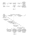
- FIG. 3 is a flow chart of the method for detecting a secondary synchronization signal according to an example of the present invention
- FIG. 4 is a block diagram of the method for detecting a secondary synchronization signal according to an example of the present invention.
- FIG. 5 is a block diagram of the process for compensating the channel estimation according to an example of the present invention.
- FIG. 6 is a schematic diagram of the position relationship between PSS and SSS and the sample buffer way in different CP mode according to an example of the present invention
- FIG. 7 is another block diagram of the process for compensating the channel estimation according to an example of the present invention.
- FIG. 8 is a schematic diagram of the FFT/IFFT scheduling policy according to an example of the present invention.
- FIG. 9 is a flow chart of the first round detection and the second round detection according to an example of the present invention.
- FIG. 10 is a block schematic diagram of the process of the first round detection according to an example of the present invention.
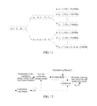
- FIG. 11 is a method for determining the cell parameter m 0 , m 1 group to be detected according to an example of the present invention
- FIG. 12 is a block schematic diagram of the process of the second round detection according to an example of the present invention.
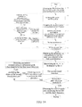
- FIG. 14 is a flow chart of the complete example for detecting the SSS according to an example of the present invention.
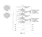
- FIG. 15 is a structure block diagram of the apparatus for detecting a secondary synchronization signal according to an example of the present invention.
- FIG. 16 is a structure block diagram of the channel estimation unit according to an example of the present invention.
- FIG. 17 is a structure block diagram of the two round detection unit according to an example of the present invention.
- FIG. 18 is a schematic diagram of the FFT/IFFT scheduling policy in a case of the known CP mode according to an example of the present invention.
- the main concept of the method and the apparatus for detecting a secondary synchronization signal of the present invention is: firstly performing the first round detection according to a coherent accumulative result of even sub-carriers in the even or odd half frames and a correlation result of the SSS sequences of the even sub-carriers, and further using the coherent accumulative results of all the sub-carriers in the even and odd half frames and SSS sequences of sub-frames 0 and sub-frames 5 of all the sub-carriers to perform the second round detection to obtain a detection result of the secondary synchronization signal based on the result of the first round detection, thereby reducing the calculation quantity of the correlation calculation.
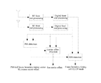
- the block diagram of receiving SSS symbols is as shown in FIG. 2 .
- the signal received by the antenna is input into the digital front end via the RF front end to be processed.
- the RF front end processing specifically comprises modules such as RF signal conditioning, filtering, down conversion, and analog to digital conversion and so on;
- the digital front end processing comprises modules such as radio frequency imperfect receiving Inphase Quadrature (IQ) data compensation, frequency offset compensation, Automatic Gain Control (AGC), down sampling filtering, and weight processing among antennae (energy balance among antennae) and so on, wherein the down sampling filtering reduces the sampling rate 30.72 MHz of the data to the sampling rate 1.92 MHz.
- the cell search part processes the time domain data processed by the digital front end.
- the cell search part mainly comprises the PSS detection, the fine carrier frequency offset detection, and the SSS detection.
- PSS detection completes 5 ms timing, namely the half frame timing, and the determination of the sector-ID and coarse carrier offset;
- the fine carrier frequency offset detection module further performs the fine frequency offset detection after the coarse carrier frequency offset adjustment;
- the SSS detection related to the present invention is the detection that uses the PSS detection positions and the sector-ID after the fine frequency offset compensation to obtain the cell ID, the radio frame boundary and the Cyclic Prefix (CP) mode. Three stages of detection can use the flow calculation in practical.
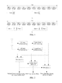
- the method for detecting a secondary synchronization signal comprises:
- step 301 a step of channel estimation compensation, in which channel estimation compensation values of each sub-carriers of the SSS symbols in different Cyclic Prefix (CP) modes are calculated;
- step 302 a step of half frame coherent accumulation, in which the coherent accumulative results of even half frames and the coherent accumulative results of odd half frames of each sub-carriers are obtained according to channel estimation compensation values of each sub-carriers of the SSS symbols;
- step 303 a step of sequence generation, in which a sequence of the secondary synchronization signal (SSS) is generated;
- SSS secondary synchronization signal
- step 304 a step of the first round detection, in which a correlation calculation is performed using the coherent accumulative results of the even sub-carriers in the even or odd half frames and the SSS sequence of the even sub-carriers to obtain the index ⁇ circumflex over (m) ⁇ i of the SSS sequence corresponding to the over-threshold value of the first round detection;
- step 306 a step of the secondary synchronization signal detection result calculation, in which the CP mode is obtained according to the parameters corresponding to the over-threshold value of the second round detection, and the cell ID and the radio frame boundary are calculated.
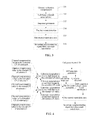
- Channel estimation compensation comprises:
- the channel estimation is performed on the PSS symbol to obtain the channel estimation value of each sub-carrier of the PSS symbol;
- the channel estimation value of each sub-carrier of the PSS symbol is approximated as the channel estimation value of each sub-carrier of the SSS symbol, which is used to perform channel estimation compensation with the transformed SSS frequency domain symbol to obtain the channel compensation value of each sub-carrier of the SSS symbol.
- the process of the channel estimation compensation of the example of the present invention comprises: buffering samples, in which the PSS symbols needed in the SSS detection and the SSS symbols in two CP modes are bufferd; obtaining PSS and SSS symbols, in which corresponding SSS symbols and the self PSS symbols are obtained according to the PSS boundary based on different antennae and CP modes, and at the same time, these symbols are transformed into the frequency domain to be processed; performing channel estimation, in which the received PSS symbol is used to perform the channel estimation, and it can be considered that channel estimation of the PSS is approximately equal to the SSS channel estimation; and performing the channel compensation, in which the channel compensation value is obtained according to the result of the channel estimation and the received SSS frequency domain symbol.
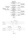
- FIG. 5 is illustrated by taking two antennae as an example.
- the way for buffering the samples according to the example of the present invention is as shown in FIG. 6 .
- the PSS detection is used to obtain the PSS boundary, and the possible SSS positions in two modes of the extended CP and normal CP can be deduced according to the type of the frame structure of the LTE configuration.
- 288 samples are continuously stored in the type of the FDD frame structure, as shown in A of FIG. 6 ;
- two segment storage is used in the type of the TDD frame structure, as shown in B of FIG. 6
- the buffer area 1 stores 196 samples
- the buffer area 2 stores 128 samples, 324 samples in sum, and therefore, the sample storage capacity is 648 samples for dual antennae without differentiating the types of the frame structure.
- the LTE system introduces 10 reserved sub-carriers (namely unused) into 6 Resource Blocks (RB) where the PSSs are situated.
- the introduction of the reserved sub-carriers causes the diffusion of the Channel Impulse Response (CIR) inside the whole symbol in the system channel estimation, thereby making the energy concentration of the multipath suffer certain damage.
- CIR Channel Impulse Response
- the multipath energy is mainly centralized at the front end and back end of the symbol, the diffused energy of the multipath in the intermediate part of the symbol is very small.
- the noise energy is usually larger than the diffused energy caused by the virtual carrier, and the threshold denoising method in the time domain is used to reduce the affect of the noise on the performance of the channel estimation performance.
- the LTE uses two different CP modes, which are respectively applied in different multipath time delay scenarios, so the channel estimation in two CP modes should be performed when the SSS detection method is used to complete the CP identification.
- the specific method as shown in FIG. 7 , comprises:
- R PSS is the received signal
- S PSS is the local PSS code
- ⁇ SC is the sub-carrier domain of the PSS allocation.
- ⁇ 1 ECP samples at the front end and ⁇ 2 ECP samples at the back end of the LS estimation value sequence in the time domain act as the channel impulse response (CIR) area of the extended CP, and other areas are noise area ⁇ noise ECP .
- ⁇ 1 NCP samples at the front end and ⁇ 2 NCP samples at the back end of the LS estimation values in the time domain act as the channel impulse response (CIR) area (wherein generally ⁇ 1 ECP > ⁇ 1 NCP and ⁇ 2 ECP > ⁇ 2 NCP ) of the normal CP, and other areas are noise area ⁇ noise NCP .
- CIR channel impulse response
- h LS , NCP ′ ⁇ ( n ) ⁇ h LS ⁇ ( n ) ⁇ h LS ⁇ ( n ) ⁇ > ⁇ ECP , n ⁇ ⁇ noise NCP 0 others
- the calculated ⁇ NCP (k), ⁇ ECP (k) are the denoised channel estimation values of the SSS symbol in the half frame.
- the following method of time division duplexing time and frequency transform buffer scheduling is used: in the processing duration of a certain antenna, performing in turn: transforming the SSS symbol from the time domain to the frequency domain in the extended CP mode, transforming the PSS symbol from the time domain to the frequency domain in the extended CP mode, transforming the channel estimation value from the frequency domain to the time domain in the extended CP mode, transforming the processed CIR from the time domain to the frequency domain in the extended CP mode, and transforming the processed CIR from the time domain to the frequency domain under the normal CP mode, and transforming SSS from the time domain to the frequency domain in the normal CP mode in sequence; the buffer firstly buffering the SSS frequency domain data in the extended CP mode in processing duration of a certain antenna and being not released until completing the channel estimation compensation in the extended CP mode, and then buffering the denoised
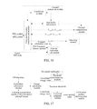
- the specific FFT/IFFT scheduling is as shown in FIG. 8 .
- 2 antennae are taken as an example, and the scheduling duration is divided into the processing duration of the antenna 0 and the processing duration of the antenna 1.
- the FFT/IFFT scheduling in the processing duration of the antenna 0 is the same with that of the antenna 1. Below it will be described by taking the FFT/IFFT scheduling of the antenna 0 as an example.
- the data buffer module stores the transformed SSS frequency domain data; then the channel estimation in the extended CP mode of the antenna 0 is performed; the channel estimation in the normal CP mode of the antenna 0 is performed after performing the SSS compensation under the extended CP mode of the antenna 0, and since the channel estimation compensation of the extended CP mode has completed the calculation at this time, the data buffer module can be released to store denoised frequency domain channel estimation values in the normal CP mode; then the FFT/IFFT module completes to transform the SSS from the time domain to the frequency domain in the normal CP mode, and data buffer module will be released after completing the SSS processing in the normal CP mode.
- the whole processing process is only required to store data of 62 sub-carriers, and the required resource consumption is minimal and the processing is more efficient.
- ⁇ *(k) denotes the conjugate of the channel estimation value of the k th sub-carrier of the SSS symbol
- R SSS (k) denotes the value of the k th sub-carrier of the transformed SSS frequency domain symbol
- ⁇ circumflex over (R) ⁇ SSS (k) denotes the channel compensation value of the k th sub-carrier of the SSS symbol.
- N denotes the number of the accumulated symbols after SSS channel compensation, namely the number of the accumulated half frames
- Q denotes the number of the receiving antennae, and 2 antennae are taken as an example to be described in the text
- ⁇ circumflex over (R) ⁇ i,2j SSS (k) denotes the channel compensation value output by the i th antenna of the k th sub-carrier in the 2j th time of coherent accumulation
- ⁇ circumflex over (R) ⁇ i,2j+1 SSS (k) denotes the channel compensation value output by the i th antenna of the k th sub-carrier in the 2j+1 th time of coherent accumulation
- a even (k), A odd (k) respectively denotes the coherent accumulation result of the even half frames and the coherent accumulation result of the odd half frames of the k th sub-carrier, and these values can be for the extended CP mode and the normal CP mode.
- the first round detection and the second round detection are both performed by following steps:
- Step 901 correlation calculation, in which the correlation values in the extended CP mode and the normal CP mode are calculated according to the coherent accumulative result of the even and/or odd half frames and the SSS sequence.
- Step 902 energy computation, in which the correlation energy value is calculated according to the correlation values.
- Step 903 determining the detection threshold, in which the average of the summation of the correlation energy value is computed to multiply the detection threshold coefficient to obtain the detection threshold, wherein the summation range of the first round detection is the correlation energy value obtained in the first round detection, and the summation range of the second round detection is the correlation energy value obtained in the first round detection and the correlation energy value obtained in the second round detection.
- Step 904 detection threshold judgment, in which the threshold judgment is performed on the correlation energy values according to the detection threshold to obtain the over-threshold correlation energy values of the first round detection or the second round detection.
- the methods of the first round detection and the second round detection are similar basically, and only the ways of the correlation calculation, the correlation energy summation ranges, the averaging factors and the threshold coefficients are different. Below the first round detection and the second round detection are respectively described.
- the SSS sequence generation is firstly completed according to the sector-ID of the PSS detection, the SSS sequence is combined by the S sequence, C sequence and Z sequence, and the specific generation can refer to 3GPP TS36.211.
- the first round detection is as shown in FIG. 10 , and comprises following steps:
- the coherent accumulative results of the even sub-carriers in the even or odd half frames are used to perform the correlation with the SSS sequence of the even sub-carriers, or the coherent accumulative result of the even sub-carriers in the odd half frames is used to perform the correlation with the SSS sequence of the even sub-carriers.
- C i is the i th correlation value of the first round correlation calculation
- d even — sc,i denotes the SSS sequence of the even sub-carrier with the i th serial number, and • denotes the point multiplication.
- P i 1 denotes the i th correlation energy value of the first round detection
- C i is the i th correlation value of the first round correlation calculation.
- the average of the summation of the correlation energy values is computed to multiply the threshold coefficient 1 to obtain the first round detection threshold, namely
- P i 1 denotes the i th correlation energy value of the first round detection
- P 1 denotes the average correlation energy value
- ⁇ 1 is the threshold coefficient 1
- T 1 is the detection threshold 1.
- the detection threshold coefficient is adjusted within the range of the times M 0 of the first round detection.
- ⁇ is the adjusting step. In the range of the times of the first round detection, once the over-threshold correlation energy value exists, then the first round detection is stopped.
- the indexes m 0 , m 1 composed of the SSS sequence used by the second round detection can be further determined by ⁇ circumflex over (m) ⁇ i , as shown in FIG. 11 .
- the second group is determined according to a following formula:
- the second round detection is basically similar to the first round detection, comprising:
- the sector-ID and m 0 , m 1 in the cases of the extended CP and the normal CP is obtained by the first round detection, and the coherent accumulative result of all the sub-carriers in the even half frames in the extended CP (or the normal CP) mode and the coherent accumulative result of all the sub-carriers in odd half frames in the extended CP (or the normal CP) mode can be used to perform the grouping joint detection.
- Grouping is firstly performed according to the value of the ⁇ j , and when the first round detection uses the coherent accumulative result of the even sub-carriers in the even half frames to perform the correlation calculation, and if ⁇ circumflex over (m) ⁇ i is m 0 , the even odd half frame collocation is used to perform the correlation; if ⁇ circumflex over (m) ⁇ i is m 1 , the odd even half frame collocation is used to perform the correlation.
- the half frame collocation way is contrary to the above, namely if ⁇ circumflex over (m) ⁇ i is m 0 , the odd even half frame collocation is used to perform the correlation; if ⁇ circumflex over (m) ⁇ i is m 1 , the even odd half frame collocation is used to perform the correlation.
- FIG. 13 shows the collocation way for performing the correlation calculation by the first round detection using the coherent accumulative result of the even sub-carriers in the even half frames.
- C even — odd and C odd — even respectively denote the even odd half frame collocation correlation value and the odd even half frame collocation correlation value;
- a odd [A odd (0), A odd (1), A odd (2), . . .
- d subframe0 (m 0 ,m 1 ) and d subframe5 (m 0 ,m 1 ) respectively denote the SSS sequences determined by the m 0 and m 1 of the sub-frame 0 and the sub-frame 5.
- the average of the summation of the first round detection correlation energy and the energy computed by the correlation value of the second round detection is computed, thereby obtaining the correlation energy average value for the second round detection.
- P i 1 denotes the i th correlation energy value of the first round detection
- P j 2 denotes the j th correlation energy value of the second round detection
- P 2 , P 2 respectively denote the total correlation energy value and the average correlation energy value applied in the second round detection.
- the second round detection corresponding to a certain index ⁇ circumflex over (m) ⁇ i of the first round detection needs M 2 times of correlation calculation, and herein the even odd half frame collocation form and the odd even half frame collocation form are included.
- ⁇ 2 is the threshold coefficient 2.
- the over-threshold correlation energy value of the second round detection corresponds to one or more ⁇ j and m 0 , and one or more cell ID group numbers are obtained according to the following formula:
- N ID cell 3 N ID (1) +N ID (2)
- N ID (2) is the sector-ID.
- the over-threshold value in the second round detection is the extended CP mode data
- the detected cell CP mode is the extended CP; conversely, it is the normal CP mode.
- the radio frame timing is the sub-frame 0 followed by the sub-frame 5; if the over-threshold value in the second round detection corresponds to the odd even half frame collocation correlation value, then the radio frame timing is the sub-frame 5 followed by the sub-frame 0.
- the specific flow for detecting the secondary synchronization signal by using the scheme of the present invention is as follows:
- the first correlation peak value is obtained by the PSS detection using to number the peak value from the large to the small, namely the maximum peak value.
- the possible SSS range is deduced by the PSS position according to the frame structure type and the CP mode, and SSS symbols and PSS symbols in two modes of the extended CP and the normal CP after performing the frequency offset compensation are buffered;
- the SSS symbols and the PSS symbols use the continuous storage way; whereas as for the TDD frame structure type, the SSS coverage data range and the PSS symbols in two CP modes are divided into two segments to be stored.
- the channel estimation is completed in two CP modes by the PSS symbols to compensate the corresponding frequency domain SSS;
- the FFT/IFFT can implement the high efficient policy of time and frequency transform buffer scheduling in the above text.
- the sector-ID corresponding to the PSS and the even sub-carrier value in the coherent accumulative result of the even/odd half frames are obtained to perform the first round detection, it is judged whether the peak value exceeding the detection threshold 1 exists, and if exists, S 6 is continued to be performed, if does not exist, the threshold coefficient 1 is gradually decreased according to the adjusting step with the times of the first round detection in the range of the times of the first round detection; if exceeding the times of the first round detection, the it is inquired whether the peak value further exists in the PSS detection table, if the peak value exists, the next result information of the current PSS detection result is obtained to continue to perform the detection, that is, the S 2 is re-entered, or else the SSS detection enters the idle state.
- ⁇ circumflex over (m) ⁇ i are also numbered from the large to small according to its corresponding peak value.
- the m 0 , m 1 to be detected are determined by the parameters ⁇ circumflex over (m) ⁇ i , and the determining method is as abovementioned;
- the coherent accumulation results of the even half frames and the odd half frames are performed the grouping joint second round detection according to the relationship between m 0 and m 1 , and it is judged whether the peak value exceeding the detection threshold 2 exists, and if exists, the S 9 is continued to be performed, if does not exist, the parameters corresponding to the subsequent peak values detected by the first round detection are re-obtained in the range of the times of the second round detection, that is, the S 7 is re-entered; if the times of the detection exceed the times of the second round detection, then the new PSS detection result is obtained to perform the SSS detection, that is, S 2 is entered;
- the above scheme of the present invention is implemented in the CP mode detection, and if the CP mode is known, the SSS detection is able to not perform the CP mode detection, and the specific flow is as follows:
- the PSS detection uses to number the peak value from the large to the small to obtain the first correlation peak value, namely the maximum peak value.
- S 2 a SSS symbols and PSS symbols after performing the frequency offset compensation are bufferd by the PSS positions according to the frame structure type and the CP mode;
- the SSS symbols and the PSS symbols use the continuous storage way; whereas as for the TDD frame structure type, the SSS symbols and the PSS symbols are divided into two segments to be stored.
- the channel estimation in the corresponding CP mode is completed by the PSS symbols to compensate the frequency domain SSS;
- the FFT/IFFT can implement the high efficient policy of time and frequency transform buffer scheduling, as shown in FIG. 18 .
- the scheduling duration is divided into the processing duration of the antenna 0 and the processing duration of the antenna 1.
- the FFT/IFFT scheduling in the processing duration of the antenna 0 is the same with that of the antenna 1. Below it will be described by taking the FFT/IFFT scheduling of the antenna 0 as an example. Firstly the SSS is transformed from the time domain to the frequency domain in the corresponding CP mode, and at this time, the data buffer module stores the transformed SSS frequency domain data; then the channel estimation in the corresponding CP mode of the antenna 0 is performed; the data buffer module releases the stored data after performing the channel compensation on the transformed SSS frequency domain data stored by the data buffer module, and SSS processing in the corresponding CP mode of the antenna 0 is completed.
- the sector-ID corresponding to the PSS and the even sub-carrier value in the coherent accumulative result of even/odd half frames are obtained to perform the first round detection, it is judged whether the peak value exceeding the detection threshold 1 exists, and if exists, S 6 a is continued to be performed, if does not exist, the threshold coefficient 1 is gradually decreased according to the adjusting step with the times of the first round detection in the range of the times of the first round detection; if exceeding the times of the first round detection, it is inquired whether the peak value further exists in the PSS detection table, if the peak value exists, the next result information of the current PSS detection result is obtained to continue to perform the detection, that is, the S 2 a is re-entered, or else the SSS detection enters the idle state.
- ⁇ circumflex over (m) ⁇ i are also numbered from the large to small according to its corresponding peak value.
- the m 0 , m 1 to be detected are determined by the parameters ⁇ circumflex over (m) ⁇ i , and the determining method is as abovementioned;
- the coherent accumulation results of the even half frames and the odd half frames are performed the group joint second round detection according to the relationship between m 0 and m 1 , it is judged whether the peak value exceeding the detection threshold 2 exists, and if exists, the S 9 a is continued to be performed, if does not exist, the parameters corresponding to the subsequent peak values detected by the first round detection are re-obtained in the range of the times of the second round detection, that is, the S 7 a is re-entered; if the times of the detection exceeds the times of the second round detection, then the new PSS detection result is obtained to perform the SSS detection, that is, S 2 a is entered;
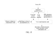
- the present invention further provides an apparatus for detecting a secondary synchronization signal, and as shown in FIG. 15 , the apparatus comprises:
- a channel estimation compensation unit which is configured to: calculate a channel estimation compensation value of each sub-carrier of a SSS symbol in different Cyclic Prefix (CP) modes or a specified CP mode;
- CP Cyclic Prefix
- This half frame coherent accumulation unit is configured to: obtain a coherent accumulative result of even half frames and a coherent accumulative result of odd half frames of each sub-carrier according to the channel estimation compensation value of each sub-carrier of the SSS symbol;
- a sequence generation unit which is configured to: generate a secondary synchronization signal (SSS) sequence;
- SSS secondary synchronization signal
- This two round detection unit is configured to: use the coherent accumulative result of even sub-carriers in the even or odd half frames and the SSS sequence of the even sub-carrier to perform the correlation calculation and compute the energy to obtain an index ⁇ circumflex over (m) ⁇ i of the SSS sequence corresponding to an over-threshold value of the first round detection; and determine indexes m 0 , m 1 composed of the SSS sequence used in the second round detection according to index ⁇ circumflex over (m) ⁇ i , use the coherent accumulative results of all the sub-carriers in the even and odd half frames and the SSS sequences of all the sub-carriers to perform the collocation correlation calculation and compute the energy to obtain an over-threshold value of the second round detection, wherein one of m 0 , m 1 is ⁇ circumflex over (m) ⁇ i , and m 1 ⁇ m 0
- this secondary synchronization signal detection result calculation unit is configured to: obtain the CP mode according to parameters corresponding to the over-threshold value of the second round detection if the channel estimation compensation unit calculates the channel estimation compensation value of each sub-carrier of the SSS symbol in different CP modes, and calculate the cell ID and the radio frame boundary; calculate the cell ID and the radio frame boundary according to parameters corresponding to the over-threshold value of the second round detection if the channel estimation compensation unit calculates the channel estimation compensation value of each sub-carrier of the SSS symbol in the specified CP mode.
- the channel estimation compensation unit has following two implementation ways:
- the channel estimation compensation unit comprises:
- a channel estimation module which is configured to: perform the time and frequency transform, which comprises: transforming the PSS symbol and the SSS symbol from the time domain to the frequency domain, and performing the channel estimation on the PSS symbol to obtain the channel estimation value of each sub-carrier of the PSS symbol which is not denoised; and
- This channel compensation module is configured to: approximate the channel estimation value of the PSS symbol as the channel estimation value of the SSS symbol, and perform the channel compensation on the transformed SSS frequency domain symbol to obtain the channel compensation value of each sub-carrier of the SSS symbol.
- the channel estimation compensation unit comprises:
- a channel estimation module which is configured to: perform the time and frequency transform, which comprises: transforming the PSS symbol and the SSS symbol to the frequency domain, transforming the channel estimation value to the time domain, transforming the threshold denoised channel impulse response to the frequency domain to obtain the denoised frequency domain channel estimation value, and performing the channel estimation on the PSS symbol to obtain the channel estimation value of each sub-carrier of the PSS symbol;
- This denoising module is configured to: perform the threshold denoising on the channel impulse response (CIR) area according to the channel estimation value transformed to the time domain; and
- This channel compensation module is configured to: use the denoised frequency domain channel estimation value and the transformed SSS frequency domain symbol to perform the channel compensation to obtain the channel compensation value of each sub-carrier of the SSS symbol.
- the channel estimation module comprises:
- control sub-module which is configured to: control the time and frequency transform sub-module and data buffer sub-module to achieve an object of the time division multiplexing of the FFT/IFFT module;
- the time and frequency transform sub-module which is configure to: implement the time and frequency domain transform of the time division duplexing under the control of the control sub-module, if the CP mode detection is performed, in the processing duration of a certain antenna, to perform in turn to: transform the SSS symbol from the time domain to the frequency domain in the extended CP mode and transform the PSS symbol from the time domain to the frequency domain, transform LS channel estimation value from the frequency domain to the time domain, transform the processed CIR from the time domain to the frequency domain in the extended CP mode, transform the processed CIR from the time domain to the frequency domain in the normal CP mode, and transform the SSS from the time domain to the frequency domain in the normal CP mode in sequence; if it is the specified CP mode, in the processing duration of a certain antenna, to perform in turn to: transform the SSS symbol from the time domain to the frequency domain in the specified CP mode, transform the PSS symbol from the time domain to the frequency domain, transform the LS channel estimation value from the frequency domain to the time domain, and transform
- the data buffer sub-module which is configured to: buffer the data after the time and frequency transform under the control of the control module, if the CP mode detection is performed, firstly buffer the SSS frequency domain data in the extended CP mode in processing duration of a certain antenna and do not release the SSS frequency domain data until completing the channel estimation compensation in the extended CP mode, and then buffer the denoised frequency domain channel estimation value in the normal CP mode and do not release the denoised frequency domain channel estimation value until completing the channel estimation compensation in the normal CP mode; if it is the specified CP mode, store the SSS frequency domain data in the specified CP mode in processing duration of a certain antenna; and
- This channel estimation sub-module is configured to: use the local PSS code and the transformed PSS frequency domain symbol to perform calculation to obtain the channel estimation value of the Least Square (LS) estimation.
- LS Least Square
- the half frame coherent accumulation unit performs the even and odd numbering on half frames where the SSS symbols or the compensated SSS symbols are located, performs the maximum ratio combining among the SSS symbol compensation value antennae of the same half frame, and performs coherent accumulation by dividing into even and odd respectively to obtain the coherent accumulative result of the even half frames and the coherent accumulative result of the odd half fames of each sub-carrier.
- Said coherent accumulation unit calculates the coherent accumulative result of the even half frames and the coherent accumulative result of the odd half fames of each sub-carrier according to following formulas.
- N denotes the number of the accumulated half frames
- Q denotes the number of the receiving antennae
- ⁇ circumflex over (R) ⁇ i,2j SSS (k) denotes the channel compensation value output by the i th antenna of the k th sub-carrier in the 2j th time of coherent accumulation
- ⁇ circumflex over (R) ⁇ i,2j+1 SSS (k) denotes the channel compensation value output by the i th antenna of the k th sub-carrier in the 2j+1 th time of coherent accumulation
- a even (k), A odd (k) respectively denotes the coherent accumulation result of the even half frames and the coherent accumulation result of the odd half frames of the k th sub-carrier.
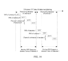
- the two round detection unit comprises:
- a correlation calculation module which is configured to: calculate the correlation values in the extended CP mode and the normal CP mode according to the coherent accumulative result of the even and/or odd half frames and the SSS sequence if the channel estimation compensation unit calculates the channel estimation compensation value of each sub-carrier of the SSS symbol in different CP modes; calculate the correlation value in the specified CP mode according to the coherent accumulative result of the even and/or odd half frames and the SSS sequence if the channel estimation compensation unit calculates the channel estimation compensation value of each sub-carrier of the SSS symbol in the specified CP mode;
- This energy calculation module is configured to: calculate the correlation energy value according to the correlation value calculated by the correlation calculation module;
- a threshold determination module which is configured to: compute the average of the summation of the correlation energy to multiply the detection threshold coefficient to obtain the detection threshold, wherein the summation range of the first round detection is the correlation energy value obtained in the first round detection, and the summation range of the second round detection is the correlation energy value obtained in the first round detection and the correlation energy value obtained in the second round detection;
- a threshold judgment module which is configured to: perform the threshold judgment on the correlation energy value obtained in the first around according to the first round detection threshold and perform the threshold judgment on the correlation energy value obtained in the second around according to the second round detection threshold;
- a collocation number determination module which is configured to: determine the indexes m 0 , m 1 composed of the SSS sequence used by the second round detection by the index ⁇ circumflex over (m) ⁇ i of the SSS sequence corresponding to the over-threshold value in the first round detection.
- the first round detection uses the coherent accumulative result of the even sub-carrier in the even half frames to perform the correlation calculation, when performing the second round detection, and if ⁇ circumflex over (m) ⁇ i is m 0 , the correlation calculation module uses the coherent accumulative results of all the sub-carriers in the even and odd half frames to respectively perform the collocation correlation with the SSS sequences of all the sub-carriers in sub-frame 0 and sub-frame 5 to obtain the even odd collocation correlation value; if ⁇ circumflex over (m) ⁇ i is m 1 , the correlation calculation module uses the coherent accumulative results of all the sub-carriers in the odd and even half frames to respectively perform the collocation correlation with the SSS sequences of all the sub-carriers in sub-frame 0 and sub-frame 5 to obtain the odd even collocation correlation value;
- the first round detection uses the coherent accumulative result of the even sub-carrier in the odd half frames to perform the correlation calculation, when performing the second round detection, and if ⁇ circumflex over (m) ⁇ i is m 1 , the correlation calculation module uses the coherent accumulative results of all the sub-carriers in the even and odd half frames to respectively perform the collocation correlation with the SSS sequences of all the sub-carriers in sub-frame 0 and sub-frame 5 to obtain the even odd collocation correlation value; if ⁇ circumflex over (m) ⁇ i is m 0 , the correlation calculation module uses the coherent accumulative results of all the sub-carriers in the odd and even half frames to respectively perform the collocation correlation with the SSS sequences of all the sub-carriers in sub-frame 0 and sub-frame 5 to obtain the odd even collocation correlation value;
- the correlation calculation module calculates the odd even half frame collocation correlation value and the even odd half frame collocation correlation value according to following formulas:
- C even — odd A even ,d subframe0 (m 0, m 1 ) + A odd ,d subframe5 (m 0, m 1 )
- C odd — even A odd ,d subframe0 (m 0 ,m 1 ) + A even ,d subframe5 (m 0 ,m 1 )
- C even — odd and C odd — even respectively denote the even and odd half frame collocation correlation value and the odd and even half frame collocation correlation value;
- a odd [A odd (0), A odd (1), A odd (2), . . .
- d subframe0 (m 0 ,m 1 ) and d subframe5 (m 0 ,m 1 ) respectively denote the SSS sequences determined by the m 0 and m 1 of the sub-frame 0 and the sub-frame 5.
- Said secondary synchronization signal detection result calculation unit obtains the cell ID group numbers are obtained according to ⁇ j and m 0 corresponding to the over-threshold value of the second round detection and the following formula:
- N ID cell 3 N ID (1) +N ID (2)
- N ID (2) is the sector-ID.
- the detected cell CP mode is the extended CP; conversely, it is the normal CP mode.
- the radio frame timing is the sub-frame 0 followed by the sub-frame 5; if the over-threshold value in the second round detection corresponds to the odd even half frame collocation correlation value, then the radio frame timing is the sub-frame 5 followed by the sub-frame 0.
- ⁇ is the adjusting step.
- the positions of the SSS sequence are at the sub-frame 0 and sub-frame 5, which is related to the definition of the protocol.
- the present invention is also applicable.
- the method and the apparatus for detecting the secondary synchronization signal of the present invention use the two round detection method to detect the SSS, which greatly reduces the calculation quantity of the correlation calculation without increasing additional resource consumption, and implements the higher efficient detection on a basis of ensuring the performance.
- the detection use the complete sequence detection
- the calculation quantity of the complete sequence detection is considerably large, but the present invention reduces the calculation quantity of the correlation in a greater degree, which obtains a very well compromise between the detection efficiency and the performance.
- the second around only needs to perform 56 times of the detection (including the CP mode detection) at most.
- the present invention uses a method based on the DFT to perform the channel estimation on the SSS, and in order to overcome the problem of the diffusion of the Channel Impulse Response (CIR) in the whole symbol in the system channel estimation caused by the introduction of the reserved sub-carriers, a threshold de-noise method is used to improve the performance of the channel estimation, which has a not large computational complexity, and it is determined whether to start the Channel Frequency Response (CFR) solution of the normal CP by a zero filling way in the extended CP mode and normal CP mode.
- CFR Channel Frequency Response
- the detection process uses multiple times of FFT/IFFT, and in order to reduce the resource consumption and achieve the calculation efficiency simultaneously, a time division multiplexing measure is used for the FFT/IFFT and a high efficient scheduling policy is applied, which occupies least resources.
- the present invention uses a method for adjusting the threshold coefficient 1 in the range of the times of the first round detection.
- the first round detection and the second round detection can use the same structures in the specific implementation of the present invention, which will not increase the additional resources.
- the method and the apparatus for detecting the secondary synchronization signal of the present invention use the two round detection method to detect the SSS, which greatly reduces the calculation quantity of the correlation calculation without increasing additional resource consumption, and implements the higher efficient detection on a basis of ensuring the performance.
- the present invention uses a threshold denoising method to improve the performance of the channel estimation, which has a not large computational complexity.
- the present invention uses multiple times of FFT/IFFT in the detection process, and applies a high efficient scheduling policy, which occupies the least resources.
Landscapes
- Engineering & Computer Science (AREA)
- Computer Networks & Wireless Communication (AREA)
- Signal Processing (AREA)
- Databases & Information Systems (AREA)
- Mobile Radio Communication Systems (AREA)
- Synchronisation In Digital Transmission Systems (AREA)
Abstract
Description
α1 i+1=α1 i −δ i=0,1,Λ,M 0−2
N ID cell=3N ID (1) +N ID (2)
α1 i+1=α1 i −δ i=0,1,Λ,M 0−2
H LS =S PSS *R PSS
h LS(n)=IFFT{H LS(k)} kεΩ SC
λECP=max{|h LS(n)|} nεΩ noise ECP
all the channel estimation values (namely the channel impulse response (CIR)) lower than the noise threshold are considered as the noise, and are set to 0.
λNCP=λECP
Ĥ ECP(k)=FFT{h′ LS,ECP(n)} kεΩ SC
Ĥ NCP(k)=FFT{h′ LS,NCP(n)} kεΩ SC
{circumflex over (R)} SSS(k)=Ĥ*(k)·R SSS(k) kεΩ SC
Ci=
P i 1 =|C i|2
α1 i+1=α1 i −δ i=0,1,Λ,M 0−2
C even
C odd
T 2=α2 ·
N ID cell=3N ID (1) +N ID (2)
C even
C odd
N ID cell=3N ID (1) +N ID (2)
α1 i+1=α1 i −δ i=0,1,Λ,M 0−2
Claims (20)
α1 i+1=α1 i −δ i=0,1,Λ,M 0−2
N ID cell=3N ID (1) +N ID (2)
α1 i+1=α1 i −δ i=0,1,Λ,M 0−2
Applications Claiming Priority (4)
| Application Number | Priority Date | Filing Date | Title |
|---|---|---|---|
| CN201010251908.1A CN102377712B (en) | 2010-08-05 | 2010-08-05 | Method and apparatus for detection on secondary synchronization signal |
| CN201010251908 | 2010-08-05 | ||
| CN201010251908.1 | 2010-08-05 | ||
| PCT/CN2011/073573 WO2012016456A1 (en) | 2010-08-05 | 2011-04-29 | Secondary synchronization signal detection method and device |
Publications (2)
| Publication Number | Publication Date |
|---|---|
| US20130176991A1 US20130176991A1 (en) | 2013-07-11 |
| US8576810B2 true US8576810B2 (en) | 2013-11-05 |
Family
ID=45558928
Family Applications (1)
| Application Number | Title | Priority Date | Filing Date |
|---|---|---|---|
| US13/380,604 Active US8576810B2 (en) | 2010-08-05 | 2011-04-29 | Method and apparatus for detecting secondary synchronization signal |
Country Status (4)
| Country | Link |
|---|---|
| US (1) | US8576810B2 (en) |
| EP (1) | EP2437453B1 (en) |
| CN (1) | CN102377712B (en) |
| WO (1) | WO2012016456A1 (en) |
Cited By (4)
| Publication number | Priority date | Publication date | Assignee | Title |
|---|---|---|---|---|
| US10405286B2 (en) | 2015-05-08 | 2019-09-03 | Samsung Electronics Co., Ltd. | Apparatus and method for synchronization signal detection |
| US10999811B2 (en) | 2019-01-24 | 2021-05-04 | Samsung Electronics Co., Ltd. | Wireless communication apparatus including synchronization signal detector and cell searching method thereof |
| US11012225B1 (en) | 2020-04-30 | 2021-05-18 | Samsung Electronics Co., Ltd. | Synchronization detection method for NR sidelink |
| US11218239B2 (en) | 2018-11-28 | 2022-01-04 | Samsung Electronics Co., Ltd. | Operating method of terminal in wireless communication system and terminal for performing the method |
Families Citing this family (51)
| Publication number | Priority date | Publication date | Assignee | Title |
|---|---|---|---|---|
| EP2374221B1 (en) | 2009-01-05 | 2019-09-11 | Marvell World Trade Ltd. | Precoding codebooks for mimo communication systems |
| US8385441B2 (en) | 2009-01-06 | 2013-02-26 | Marvell World Trade Ltd. | Efficient MIMO transmission schemes |
| US8238483B2 (en) | 2009-02-27 | 2012-08-07 | Marvell World Trade Ltd. | Signaling of dedicated reference signal (DRS) precoding granularity |
| JP5607143B2 (en) | 2009-04-21 | 2014-10-15 | マーベル ワールド トレード リミテッド | COMMUNICATION METHOD, COMMUNICATION DEVICE, MOBILE COMMUNICATION TERMINAL, CHIPSET, AND COMMUNICATION SYSTEM |
| US8675794B1 (en) | 2009-10-13 | 2014-03-18 | Marvell International Ltd. | Efficient estimation of feedback for modulation and coding scheme (MCS) selection |
| US8917796B1 (en) | 2009-10-19 | 2014-12-23 | Marvell International Ltd. | Transmission-mode-aware rate matching in MIMO signal generation |
| EP2499862B1 (en) | 2009-11-09 | 2018-09-05 | Marvell World Trade Ltd. | Asymmetrical feedback for coordinated transmission systems |
| CN102687456B (en) * | 2010-01-07 | 2015-04-15 | 马维尔国际贸易有限公司 | Method and device for dedicated reference signal (DRS) precoding granularity signaling |
| JP5258002B2 (en) | 2010-02-10 | 2013-08-07 | マーベル ワールド トレード リミテッド | Device, mobile communication terminal, chipset, and method in MIMO communication system |
| US8687741B1 (en) * | 2010-03-29 | 2014-04-01 | Marvell International Ltd. | Scoring hypotheses in LTE cell search |
| JP2012100254A (en) | 2010-10-06 | 2012-05-24 | Marvell World Trade Ltd | Codebook subsampling for pucch feedback |
| US9048970B1 (en) | 2011-01-14 | 2015-06-02 | Marvell International Ltd. | Feedback for cooperative multipoint transmission systems |
| US8861391B1 (en) | 2011-03-02 | 2014-10-14 | Marvell International Ltd. | Channel feedback for TDM scheduling in heterogeneous networks having multiple cell classes |
| EP2692068B1 (en) | 2011-03-31 | 2019-06-19 | Marvell World Trade Ltd. | Channel feedback for cooperative multipoint transmission |
| US8923427B2 (en) | 2011-11-07 | 2014-12-30 | Marvell World Trade Ltd. | Codebook sub-sampling for frequency-selective precoding feedback |
| WO2013068915A2 (en) | 2011-11-07 | 2013-05-16 | Marvell World Trade Ltd. | Precoding feedback for cross-polarized antennas with magnitude information |
| US9031597B2 (en) | 2011-11-10 | 2015-05-12 | Marvell World Trade Ltd. | Differential CQI encoding for cooperative multipoint feedback |
| US9220087B1 (en) | 2011-12-08 | 2015-12-22 | Marvell International Ltd. | Dynamic point selection with combined PUCCH/PUSCH feedback |
| US8902842B1 (en) | 2012-01-11 | 2014-12-02 | Marvell International Ltd | Control signaling and resource mapping for coordinated transmission |
| EP2639982B1 (en) * | 2012-03-15 | 2015-01-14 | ST-Ericsson SA | A receiver and a method therein |
| US9143189B2 (en) * | 2012-03-30 | 2015-09-22 | Broadcom Corporation | Mobile device searching using multiple antennas |
| WO2013160795A1 (en) | 2012-04-27 | 2013-10-31 | Marvell World Trade Ltd. | Coordinated multipoint (comp) communication between base-stations and mobile communication terminals |
| CN103428146B (en) * | 2012-05-24 | 2017-08-25 | 南京中兴软件有限责任公司 | The detection method and device of auxiliary synchronous signals |
| KR102053764B1 (en) * | 2012-08-01 | 2019-12-09 | 한국전자통신연구원 | Apparatus and method for detecting code |
| CN103595442B (en) * | 2012-08-14 | 2015-10-14 | 富士通株式会社 | Cell search apparatus, receiver and method thereof |
| US9614700B2 (en) * | 2013-01-02 | 2017-04-04 | Qualcomm Incorporated | Techniques for channel estimation in millimeter-wave communication systems |
| EP3651521B1 (en) | 2013-01-18 | 2021-05-19 | Huawei Technologies Co., Ltd. | Detecting method and apparatus for common control channel |
| CN104065604B (en) * | 2013-03-21 | 2017-09-29 | 联想(北京)有限公司 | Signal synchronizing method, receiving terminal and system |
| CN104518999B (en) * | 2013-09-29 | 2019-03-12 | 锐迪科(重庆)微电子科技有限公司 | Determine the method, system and mobile terminal of Reference Signal Received Power |
| CN111343694B (en) * | 2014-01-24 | 2021-12-10 | 华为技术有限公司 | Information transmission method, user equipment and base station |
| WO2015109513A1 (en) | 2014-01-24 | 2015-07-30 | 华为技术有限公司 | Information transmission method, user equipment and base station |
| DE102014104090B4 (en) * | 2014-03-25 | 2020-08-13 | Intel IP Corporation | Method and related mobile device for cell search with low memory requirements |
| US9584245B2 (en) * | 2014-03-26 | 2017-02-28 | National Central University | Non-coherent neighbor cell searching method |
| CN110545578B (en) | 2014-08-11 | 2021-09-24 | Lg 电子株式会社 | Method for transmitting synchronization signal in wireless communication system |
| CN105578601B (en) * | 2014-10-15 | 2019-02-12 | 普天信息技术有限公司 | A conflict control method and system for discovery signals |
| CN105988972B (en) * | 2015-02-03 | 2018-12-07 | 上海澜至半导体有限公司 | Realize Fast Fourier Transform (FFT)/inverse fast Fourier transform method and circuit |
| US9755881B1 (en) * | 2015-07-28 | 2017-09-05 | Marvell Israel (M.I.S.L) Ltd. | Receiver with data-aided automatic frequency control |
| EP3590241A1 (en) * | 2017-03-03 | 2020-01-08 | Intel IP Corporation | Transmission of synchronization signals |
| KR102282868B1 (en) * | 2017-04-25 | 2021-07-28 | 삼성전자주식회사 | Method and apparatus for channel estimation in wireless communication system |
| CN108811077B (en) * | 2017-05-05 | 2020-10-09 | 电信科学技术研究院 | Generation method, detection method, base station and user equipment of secondary synchronization sequence |
| CN107181558B (en) * | 2017-07-20 | 2019-04-09 | 武汉虹信通信技术有限责任公司 | A kind of neighbor cell detecting method and device based on LTE system |
| US10334516B1 (en) * | 2018-03-13 | 2019-06-25 | Hong Kong Applied Science And Technology Research Institute Co., Ltd. | Cell search in a wireless network |
| CN112205059B (en) * | 2018-05-29 | 2024-05-03 | 上海诺基亚贝尔股份有限公司 | Method, apparatus and computer readable medium for signal detection |
| US11452058B2 (en) | 2018-11-09 | 2022-09-20 | Samsung Electronics Co., Ltd | Apparatus and method for cell detection by combining secondary spreading sequences |
| CN111294136B (en) * | 2019-04-09 | 2022-03-22 | 锐迪科微电子(上海)有限公司 | Cell search method, receiver, user terminal, and computer-readable storage medium |
| CN111294294A (en) * | 2019-05-15 | 2020-06-16 | 展讯通信(上海)有限公司 | Cell search method, user terminal, and computer-readable storage medium |
| CN110266632B (en) * | 2019-07-03 | 2022-05-17 | 国网信息通信产业集团有限公司 | A method and device for generating a primary synchronization sequence |
| CN113993145B (en) * | 2021-11-01 | 2024-03-15 | 上海创远仪器技术股份有限公司 | Method, device, processor and computer readable storage medium for realizing NR downlink multi-cell detection processing in mobile communication system |
| CN116137734A (en) * | 2021-11-16 | 2023-05-19 | 中兴通讯股份有限公司 | Cell searching method, device, electronic equipment and storage medium |
| CN114363136B (en) * | 2022-01-11 | 2024-05-28 | 重庆邮电大学 | Accurate frequency offset estimation method of 5G NR based on cell search SSB block index |
| CN115801178A (en) * | 2022-11-30 | 2023-03-14 | 北京奕斯伟计算技术股份有限公司 | Interference signal suppression method and device |
Citations (5)
| Publication number | Priority date | Publication date | Assignee | Title |
|---|---|---|---|---|
| CN101102125A (en) | 2007-08-09 | 2008-01-09 | 中兴通讯股份有限公司 | Auxiliary synchronization channel scrambling method and corresponding cell searching mode |
| CN101267226A (en) | 2007-03-14 | 2008-09-17 | 中兴通讯股份有限公司 | An information sending method for auxiliary synchronization channel and cell search method |
| WO2009023670A2 (en) | 2007-08-13 | 2009-02-19 | Qualcomm Incorporated | Secondary synchronization codebook for e-utran |
| US8009701B2 (en) * | 2007-08-13 | 2011-08-30 | Qualcomm Incorporated | Secondary synchronization codebook for E-utran |
| US20110274097A1 (en) * | 2010-05-07 | 2011-11-10 | Qualcomm Incorporated | Detecting and reporting physical-layer cell identifier collisions in wireless networks |
Family Cites Families (1)
| Publication number | Priority date | Publication date | Assignee | Title |
|---|---|---|---|---|
| US8170592B2 (en) * | 2008-09-12 | 2012-05-01 | Broadcom Corporation | Method and system for frame timing acquisition in evolved universal terrestrial radio access (EUTRA) |
-
2010
- 2010-08-05 CN CN201010251908.1A patent/CN102377712B/en active Active
-
2011
- 2011-04-29 EP EP11796597.0A patent/EP2437453B1/en active Active
- 2011-04-29 US US13/380,604 patent/US8576810B2/en active Active
- 2011-04-29 WO PCT/CN2011/073573 patent/WO2012016456A1/en active Application Filing
Patent Citations (5)
| Publication number | Priority date | Publication date | Assignee | Title |
|---|---|---|---|---|
| CN101267226A (en) | 2007-03-14 | 2008-09-17 | 中兴通讯股份有限公司 | An information sending method for auxiliary synchronization channel and cell search method |
| CN101102125A (en) | 2007-08-09 | 2008-01-09 | 中兴通讯股份有限公司 | Auxiliary synchronization channel scrambling method and corresponding cell searching mode |
| WO2009023670A2 (en) | 2007-08-13 | 2009-02-19 | Qualcomm Incorporated | Secondary synchronization codebook for e-utran |
| US8009701B2 (en) * | 2007-08-13 | 2011-08-30 | Qualcomm Incorporated | Secondary synchronization codebook for E-utran |
| US20110274097A1 (en) * | 2010-05-07 | 2011-11-10 | Qualcomm Incorporated | Detecting and reporting physical-layer cell identifier collisions in wireless networks |
Non-Patent Citations (1)
| Title |
|---|
| International Search Report for PCT/CN2011/073573 dated Jul. 14, 2011. |
Cited By (5)
| Publication number | Priority date | Publication date | Assignee | Title |
|---|---|---|---|---|
| US10405286B2 (en) | 2015-05-08 | 2019-09-03 | Samsung Electronics Co., Ltd. | Apparatus and method for synchronization signal detection |
| US11218239B2 (en) | 2018-11-28 | 2022-01-04 | Samsung Electronics Co., Ltd. | Operating method of terminal in wireless communication system and terminal for performing the method |
| US10999811B2 (en) | 2019-01-24 | 2021-05-04 | Samsung Electronics Co., Ltd. | Wireless communication apparatus including synchronization signal detector and cell searching method thereof |
| US11930468B2 (en) | 2019-01-24 | 2024-03-12 | Samsung Electronics Co., Ltd. | Wireless communication apparatus including synchronization signal detector and cell searching method thereof |
| US11012225B1 (en) | 2020-04-30 | 2021-05-18 | Samsung Electronics Co., Ltd. | Synchronization detection method for NR sidelink |
Also Published As
| Publication number | Publication date |
|---|---|
| CN102377712B (en) | 2014-07-02 |
| EP2437453A1 (en) | 2012-04-04 |
| WO2012016456A1 (en) | 2012-02-09 |
| CN102377712A (en) | 2012-03-14 |
| US20130176991A1 (en) | 2013-07-11 |
| EP2437453A4 (en) | 2017-08-16 |
| EP2437453B1 (en) | 2019-04-24 |
Similar Documents
| Publication | Publication Date | Title |
|---|---|---|
| US8576810B2 (en) | Method and apparatus for detecting secondary synchronization signal | |
| KR101291859B1 (en) | Methods and systems for improved timing acquisition for varying channel conditions | |
| CN102148785B (en) | Methods and devices for detecting main synchronous signal and generating sequence in LTE (Long Term Evolution) system | |
| KR100899316B1 (en) | Signal acquisition in a wireless communication system | |
| CN102130883B (en) | Time frequency synchronization method for time division long-term evolution (TD-LTE) system | |
| CN102812679B (en) | For method and the device of accurate time synchronization in wireless telecommunication system | |
| US8300713B2 (en) | Preamble sequence detection and integral carrier frequency offset estimation method for OFDM/OFDMA wireless communication system | |
| US8744013B2 (en) | Channel estimation for OFDM systems | |
| CN108832965B (en) | A kind of method and device of determining upstream synchronous timing deviation | |
| US8718099B2 (en) | Transmission apparatus, transmission method, reception apparatus, and reception method | |
| EP2628254B1 (en) | Uplink noise estimation for virtual mimo | |
| JP4339362B2 (en) | Method and apparatus for detecting cells in an orthogonal frequency division multiple access system | |
| US20060083160A1 (en) | Apparatus and method for estimating uplink frequency offset in an orthogonal frequency division multiplexing communication system | |
| US9961655B1 (en) | Method and apparatus for low complexity frequency synchronization in LTE wireless communication systems | |
| WO2008135541A1 (en) | Determining a frequency error in a receiver of a wireless communications system | |
| CN110971558A (en) | CAZAC sequence-based low-complexity anti-frequency offset synchronization method | |
| CN102209052A (en) | Method and device for carrying out frequency offset compensation on random access signals | |
| CN102461102A (en) | Channel estimation process according to PSS signal in LTE communication network and receiver thereof | |
| CA2570273A1 (en) | Method and apparatus for channel estimation using pilots | |
| US9674808B1 (en) | Method and apparatus for early frequency synchronization in LTE wireless communication systems | |
| US10212679B1 (en) | Method and apparatus for delay spread estimation | |
| EP2095588A1 (en) | Method of and apparatus for adaptive frequency error estimation | |
| CN102832981B (en) | A kind of method and apparatus for determining time synchronized position | |
| TW201110633A (en) | Methods and systems for time tracking in OFDM systems | |
| TWI542233B (en) | Method and apparatus for cell search and synchronization in mobile communication |
Legal Events
| Date | Code | Title | Description |
|---|---|---|---|
| AS | Assignment |
Owner name: ZTE CORPORATION, CHINA Free format text: ASSIGNMENT OF ASSIGNORS INTEREST;ASSIGNOR:YI, LIQIANG;REEL/FRAME:027441/0337 Effective date: 20111216 |
|
| STCF | Information on status: patent grant |
Free format text: PATENTED CASE |
|
| AS | Assignment |
Owner name: ZTE MICROELECTRONICS TECHNOLOGY CO.LTD, CHINA Free format text: ASSIGNMENT OF ASSIGNORS INTEREST;ASSIGNOR:ZTE CORPORATION;REEL/FRAME:037137/0229 Effective date: 20151109 |
|
| FPAY | Fee payment |
Year of fee payment: 4 |
|
| AS | Assignment |
Owner name: SANECHIPS TECHNOLOGY CO., LTD., CHINA Free format text: CHANGE OF NAME;ASSIGNOR:ZTE MICROELECTRONICS TECHNOLOGY CO., LTD;REEL/FRAME:042389/0938 Effective date: 20161111 |
|
| MAFP | Maintenance fee payment |
Free format text: PAYMENT OF MAINTENANCE FEE, 8TH YEAR, LARGE ENTITY (ORIGINAL EVENT CODE: M1552); ENTITY STATUS OF PATENT OWNER: LARGE ENTITY Year of fee payment: 8 |
|
| MAFP | Maintenance fee payment |
Free format text: PAYMENT OF MAINTENANCE FEE, 12TH YEAR, LARGE ENTITY (ORIGINAL EVENT CODE: M1553); ENTITY STATUS OF PATENT OWNER: LARGE ENTITY Year of fee payment: 12 |