US8570154B2 - Method for operating a system of readers - Google Patents
Method for operating a system of readers Download PDFInfo
- Publication number
- US8570154B2 US8570154B2 US12/960,471 US96047110A US8570154B2 US 8570154 B2 US8570154 B2 US 8570154B2 US 96047110 A US96047110 A US 96047110A US 8570154 B2 US8570154 B2 US 8570154B2
- Authority
- US
- United States
- Prior art keywords
- reader
- readers
- active mode
- processor
- standby mode
- Prior art date
- Legal status (The legal status is an assumption and is not a legal conclusion. Google has not performed a legal analysis and makes no representation as to the accuracy of the status listed.)
- Active, expires
Links
Images


Classifications
-
- G—PHYSICS
- G06—COMPUTING OR CALCULATING; COUNTING
- G06K—GRAPHICAL DATA READING; PRESENTATION OF DATA; RECORD CARRIERS; HANDLING RECORD CARRIERS
- G06K7/00—Methods or arrangements for sensing record carriers, e.g. for reading patterns
- G06K7/0008—General problems related to the reading of electronic memory record carriers, independent of its reading method, e.g. power transfer
Definitions
- the present invention relates to a method for operating a system of readers and, more particularly, to a method for operating a system of readers with an exchange mechanism.
- Radio frequency identification is used in various fields.
- RFID is a non-contact automatic identification technique based on transmission of radio for carrying data. With RFID, a large amount of data can be identified in a short period of time. Hence, for automatic control of vehicles, persons and cargo in airports, RFID is often used instead of the barcode identification technique. RFID has accomplished what other identification techniques cannot. Unlike the barcode identification technique, RFID does not require contact of a reader with a tag or alignment of the reader with the target tag. In addition, the tags used in RFID are less vulnerable to contaminants than the tags used in the barcode identification technique. Furthermore, there is more flexibility in locating the tags used in RFID than the barcode identification technique. For example, a tag used in RFID can be sandwiched between two layers of paper of a box.
- RFID is based on inductive coupling or propagation coupling.
- a tag is attached to an object by adhesion, insertion, hanging or implanting.
- the tag provides the reader with data such as an ID number.
- the data are decoded in the reader.
- the decoded data are sent to another apparatus for further processing.
- a typical RFID system includes a reader 11 , a tag 12 and an antenna 13 .
- the reader 11 sends a signal to the tag 12 so that the reader 11 actuates and recharges the tag 12 in an electro-magnetic field. Recharged, the tag 12 transmits data to the reader 11 .
- the read 11 decodes the data and broadcasts the decoded data via the antenna 13 .
- a processor such as a computer receives the decoded data and takes actions according to the decoded data.
- RFID systems can be classified into low frequency systems (“LF”) operated at 125 KHz, high frequency systems (“HF”) operated at about 13.56 MHz, ultra high frequency systems (“UHF”) operated at 900 MHz, and microwave systems operated at 2.4 GHz or 5.8 GHz.
- An RFID system may include a portable or stationary reader.
- a portable reader is often carried and used by a person in an inventory check.
- a stationary reader is often attached to a door or gate of a factory. The stationary reader is expected to be more reliable than the portable reader. However, the stationary reader might lose or damage the data because the power of the transmission of the radio drops or the efficiency of the operation of a processor located therein drops after a long period of service.
- the stationary reader is equipped with a trigger. After the RFID system is turned on, the trigger begins to work.
- the trigger puts the reader in a standby mode if it does not detect any object.
- the trigger sends a signal to the reader if it detects an object. With the signal, the reader beings to search for, actuate, recharge and receive data from a tag. Then, the reader returns to the standby mode, and waits for another signal from the trigger.
- the reading efficiency and range might decrease after a long period of service.
- the abnormal operation of the reader might last too long to keep the data in the reader.
- the present invention is therefore intended to obviate or at least alleviate the problems encountered in prior art.
- the method includes the steps of providing a processor to produce a command, using the command to get the first reader in an active mode and the second reader in a standby mode, waking up the second reader so that the first and second readers are in the active mode at the same time, and switching the first reader to the standby mode and retaining the second reader in the active mode.
- FIG. 1 is a block diagram of a conventional RFID system
- FIG. 2 is a block diagram of an RFID system according to the preferred embodiment of the present invention.
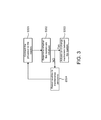
- FIG. 3 is a flow chart of a method for operating the RFID system shown in FIG. 2 ;
- FIG. 4 is a more detailed flow chart of the method shown in FIG. 3 ;
- FIG. 5 is a more detailed flow chart of the method shown in FIG. 4 .
- an RFID system includes a first reader 21 , a second reader 22 , a processor 23 and an electronic tag 24 according to the preferred embodiment of the present invention. There is also radio communication between the first reader 21 and the electronic tag 24 . There is radio communication between the electronic tag 24 and each of the reader 22 and 24 .
- the electronic tag 24 can be made as a card, token or any other proper configuration.
- the processor 23 is connected to each of the readers 21 and 22 .
- the communication of the processor 23 with each of the readers 21 and 22 can be done via a UDP web so that each of the readers 21 and 22 actively accesses to the processor 23 , which plays a passive role.
- the communication of the processor 23 with each of the readers 21 and 22 can be conducted via TCP/IP so that the processors 23 actively access to each of the readers 21 and 22 at a certain IP address.
- the processor 23 determines whether each of the readers 21 and 22 is initialized. The process goes to S 303 if the readers 21 and 22 are initialized and ready to execute commands from the processor 23 . Otherwise, the process goes to S 304 .
- the processor 23 actuates an exchange mechanism between the readers 21 and 22 .
- the processor 23 reports troubles to maintenance personnel. After trouble shooting, the processor 23 returns to S 301 .
- the exchange mechanism is shown.
- the processor 23 provides a command 41 to each of the readers 21 and 22 .
- the command 41 gets the first reader 21 in an active mode and the second reader 22 in a standby mode.
- the processor 23 wakes up the second reader 22 so that both of the readers 21 and 22 are in the active mode at the same time.
- the command 41 switches the first reader 21 to the standby mode but keeps the second reader 22 in the active mode.
- the processor 23 provides a command 41 to each of the readers 21 and 22 .
- the command 41 gets the first reader 21 in an active mode and the second reader 22 in a standby mode.
- the processor 23 determines whether the first reader 21 is successfully located in the active mode and the second reader 22 is successfully located in the standby mode.
- the process goes to S 307 if the first reader 21 is in the active mode and the second reader 22 is in the standby mode.
- the process goes to S 304 the first reader 21 is not in the active mode and/or the second reader 22 is not in the standby mode.
- the second reader 22 wakes up from the standby mode for every 30 or 60 minutes for example. Temporarily in the active mode, the second reader 22 connects to the proc processor 23 . After successfully connecting to the processor 23 , the second reader 22 soon returns to the standby mode.
- the communication of the processor 23 with each of the readers 21 and 22 can be done via a UDP web so that each of the readers 21 and 22 actively accesses to the processor 23 , which plays a passive role.
- the communication of the processor 23 with each of the readers 21 and 22 can be conducted via TCP/IP so that the processors 23 actively access to each of the readers 21 and 22 at a certain IP address.
- the processor 23 wakes up the second reader 22 so that both of the readers 21 and 22 are in the active mode at the same time.
- the readers 21 and 22 exchange data when both of them are in the active mode. Hence, there are two identical copies of the data, one in the first reader 21 and the other in the second reader 22 . The risks of the data lost are reduced.
- the command 41 switches the first reader 21 to the standby mode but keeps the second reader 22 in the active mode.
- the readers 21 and 22 take turns to work. Hence, each of the readers 21 and 22 is put to rest from time to time, and its life is extended. Moreover, the processor 23 actively reports troubles to the maintenance personnel for instant trouble shooting. Hence, the risks of losing the data due to failure of the readers 21 and 22 for a long time are reduced.
Landscapes
- Engineering & Computer Science (AREA)
- Artificial Intelligence (AREA)
- Computer Vision & Pattern Recognition (AREA)
- Physics & Mathematics (AREA)
- General Physics & Mathematics (AREA)
- Theoretical Computer Science (AREA)
- Near-Field Transmission Systems (AREA)
- Mobile Radio Communication Systems (AREA)
- Time Recorders, Dirve Recorders, Access Control (AREA)
- Lock And Its Accessories (AREA)
Abstract
Description
Claims (10)
Applications Claiming Priority (3)
| Application Number | Priority Date | Filing Date | Title |
|---|---|---|---|
| TW099128558 | 2010-08-26 | ||
| TW099128558A TW201209725A (en) | 2010-08-26 | 2010-08-26 | Operation method of card reading device system |
| TW99128558A | 2010-08-26 |
Publications (2)
| Publication Number | Publication Date |
|---|---|
| US20120050014A1 US20120050014A1 (en) | 2012-03-01 |
| US8570154B2 true US8570154B2 (en) | 2013-10-29 |
Family
ID=45218152
Family Applications (1)
| Application Number | Title | Priority Date | Filing Date |
|---|---|---|---|
| US12/960,471 Active 2032-05-14 US8570154B2 (en) | 2010-08-26 | 2010-12-04 | Method for operating a system of readers |
Country Status (3)
| Country | Link |
|---|---|
| US (1) | US8570154B2 (en) |
| EP (1) | EP2423846B1 (en) |
| TW (1) | TW201209725A (en) |
Families Citing this family (2)
| Publication number | Priority date | Publication date | Assignee | Title |
|---|---|---|---|---|
| DE102013113978A1 (en) * | 2013-12-12 | 2015-06-18 | Harting Kgaa | Modular RFID reader |
| CN106384506B (en) * | 2016-09-03 | 2019-07-12 | 湖北鑫美企业发展股份有限公司 | A kind of preventing road monitoring system of more vehicle complicated highway sections |
Citations (1)
| Publication number | Priority date | Publication date | Assignee | Title |
|---|---|---|---|---|
| US20090009295A1 (en) * | 2007-03-30 | 2009-01-08 | Broadcom Corporation | Transceiver with far field and near field operation and methods for use therewith |
Family Cites Families (1)
| Publication number | Priority date | Publication date | Assignee | Title |
|---|---|---|---|---|
| JP4887627B2 (en) * | 2005-01-19 | 2012-02-29 | 日本電気株式会社 | RFID reading system, RFID reading method, RFID reader, RFID reading management apparatus, RFID reader control program and computer-readable information recording medium, and RFID reading management apparatus control program and computer recording the same Possible information recording media |
-
2010
- 2010-08-26 TW TW099128558A patent/TW201209725A/en unknown
- 2010-12-04 US US12/960,471 patent/US8570154B2/en active Active
- 2010-12-21 EP EP10196364.3A patent/EP2423846B1/en active Active
Patent Citations (1)
| Publication number | Priority date | Publication date | Assignee | Title |
|---|---|---|---|---|
| US20090009295A1 (en) * | 2007-03-30 | 2009-01-08 | Broadcom Corporation | Transceiver with far field and near field operation and methods for use therewith |
Also Published As
| Publication number | Publication date |
|---|---|
| EP2423846A3 (en) | 2012-10-03 |
| EP2423846B1 (en) | 2014-06-25 |
| EP2423846A2 (en) | 2012-02-29 |
| TW201209725A (en) | 2012-03-01 |
| US20120050014A1 (en) | 2012-03-01 |
Similar Documents
| Publication | Publication Date | Title |
|---|---|---|
| US7929910B2 (en) | Portable electronic apparatus with near field communication (NFC) application and method of operating the portable electronic apparatus | |
| US8416063B2 (en) | Method and apparatus for stopping power supply in RFID system | |
| US9092680B2 (en) | Active logistical tag for cargo | |
| EP2320349A2 (en) | RFID reader | |
| EP2101287A1 (en) | Active RFID tag | |
| US20080252426A1 (en) | Intelligent Rfid System For Low Powered Reader-Tag Communication and Method Thereof | |
| WO2007149218A2 (en) | Rfid tag user memory indication | |
| CN101359358A (en) | Label recognizing system, label accessing device and label sposition determining method | |
| US20060202804A1 (en) | Sleep command for active RF tags to prolong battery life | |
| CN103116734A (en) | Anti-collision method of RFID (Radio Frequency Identification) system based on power control | |
| US11039538B2 (en) | Communication system including antennas on flexible circuit board | |
| US20140266612A1 (en) | Passive near field id for correlating asset with mobile tracker | |
| US8570154B2 (en) | Method for operating a system of readers | |
| KR20060112976A (en) | Radio Frequency Recognition System and Control Method | |
| CN105164702A (en) | Excess radio-frequency (rf) power storage in rf identification (rfid) tags, and related systems and methods | |
| KR20070088154A (en) | Apparatus and method incorporating RFID reading function and Internet communication function | |
| Yang et al. | The simulation and analysis of algorithms for redundant reader elimination in RFID system | |
| JP5895744B2 (en) | Wireless power supply type RFID tag system | |
| JP2008305183A (en) | Configuration management device | |
| CN100517376C (en) | radio frequency identification monitoring system and method | |
| KR101046150B1 (en) | Ubiquitous sensor node device and system for switchgear | |
| CN103034883B (en) | Radio-frequency identification method and system | |
| KR20090107456A (en) | Radio recognition tag data relay system | |
| Li | Application process algorithm analysis of RFID technology | |
| KR20070104047A (en) | Event management system and method according to user's life pattern |
Legal Events
| Date | Code | Title | Description |
|---|---|---|---|
| AS | Assignment |
Owner name: CHUNG-SAN INSTITUTE OF SCIENCE AND TECHNOLOGY, ARM Free format text: ASSIGNMENT OF ASSIGNORS INTEREST;ASSIGNORS:TSAI, WEN-CHIEH;LEE, MING-TOWN;LEE, LONG-GUANG;SIGNING DATES FROM 20101110 TO 20101117;REEL/FRAME:025449/0094 |
|
| STCF | Information on status: patent grant |
Free format text: PATENTED CASE |
|
| AS | Assignment |
Owner name: NATIONAL CHUNG SHAN INSTITUTE OF SCIENCE AND TECHN Free format text: CHANGE OF NAME;ASSIGNOR:CHUNG-SAN INSTITUTE OF SCIENCE AND TECHNOLOGY, ARMAMENTS, BUREAU, MINISTRY OF NATIONAL DEFENSE;REEL/FRAME:035432/0702 Effective date: 20140129 |
|
| FPAY | Fee payment |
Year of fee payment: 4 |
|
| MAFP | Maintenance fee payment |
Free format text: PAYMENT OF MAINTENANCE FEE, 8TH YEAR, LARGE ENTITY (ORIGINAL EVENT CODE: M1552); ENTITY STATUS OF PATENT OWNER: LARGE ENTITY Year of fee payment: 8 |
|
| MAFP | Maintenance fee payment |
Free format text: PAYMENT OF MAINTENANCE FEE, 12TH YEAR, LARGE ENTITY (ORIGINAL EVENT CODE: M1553); ENTITY STATUS OF PATENT OWNER: LARGE ENTITY Year of fee payment: 12 |