US8565800B2 - Wireless base station, and method of selecting mobile terminal - Google Patents
Wireless base station, and method of selecting mobile terminal Download PDFInfo
- Publication number
- US8565800B2 US8565800B2 US12/987,126 US98712611A US8565800B2 US 8565800 B2 US8565800 B2 US 8565800B2 US 98712611 A US98712611 A US 98712611A US 8565800 B2 US8565800 B2 US 8565800B2
- Authority
- US
- United States
- Prior art keywords
- mobile terminal
- mobile terminals
- base station
- matrix
- wireless base
- Prior art date
- Legal status (The legal status is an assumption and is not a legal conclusion. Google has not performed a legal analysis and makes no representation as to the accuracy of the status listed.)
- Expired - Fee Related, expires
Links
Images


Classifications
-
- H—ELECTRICITY
- H04—ELECTRIC COMMUNICATION TECHNIQUE
- H04B—TRANSMISSION
- H04B7/00—Radio transmission systems, i.e. using radiation field
-
- H—ELECTRICITY
- H04—ELECTRIC COMMUNICATION TECHNIQUE
- H04B—TRANSMISSION
- H04B7/00—Radio transmission systems, i.e. using radiation field
- H04B7/02—Diversity systems; Multi-antenna system, i.e. transmission or reception using multiple antennas
- H04B7/04—Diversity systems; Multi-antenna system, i.e. transmission or reception using multiple antennas using two or more spaced independent antennas
- H04B7/0413—MIMO systems
- H04B7/0452—Multi-user MIMO systems
Definitions
- the present invention relates to a wireless base station which performs wireless communication with a mobile terminal and which is used in a MOMO (Multiple Input Multiple Output) communication system, and a method of selecting a mobile terminal in the wireless base station.
- MOMO Multiple Input Multiple Output
- a MIMO (Multiple Input Multiple Output) communication system As a wireless communication system for improving a transmission rate by spatial multiplexing, or for improving reliability by a diversity effect using different propagation characteristics of a plurality of paths, a MIMO (Multiple Input Multiple Output) communication system has been proposed.
- a wireless base station including a plurality of antennas can simultaneously transmit data to a plurality of mobile terminals by using the plurality of antenna.
- the wireless base station may select a communication-target mobile terminal (or communication-target mobile terminals) from the plurality of mobile terminal. Namely, the wireless base station may perform user scheduling process. Thereby the wireless base station may perform communication (i.e. data transmission and data reception) with the mobile terminal.
- Patent document 1 Japanese Patent Application Laid Open No. 2007-20188
- the communication-target mobile terminal (or communication-target mobile terminals) from the plurality of mobile terminals
- the channel capacities or the like are calculated by arithmetic operation for all the candidates of combinations of the selected mobile terminals (or the selected mobile terminal). Then, one combination of the mobile terminals (or the mobile terminal) which can realize the optimum or maximum channel capacity is selected.
- the wireless base station calculates the channel capacity or the like for each of the M C N types of combinations of the mobile terminals (or the mobile terminal).
- N is an integer satisfying 1 ⁇ N ⁇ M
- M is an integer more than 1
- the wireless base station calculates the channel capacity or the like for each of the M C N types of combinations of the mobile terminals (or the mobile terminal).
- the number of the mobile terminals increases, the amount of arithmetic operation becomes enormous, which is technically problematic.
- a wireless base station performs multiple input multiple output communication with a plurality of mobile terminals.
- the wireless base station includes a selecting unit; and an updating unit.
- the selecting unit selects a mobile terminal, which realizes such a condition that a parameter satisfies a predetermined criterion, from the plurality of mobile terminals.
- the parameter is defined by an inverse matrix of a predetermined matrix.
- the predetermined matrix for example, there is listed a matrix used to calculate a channel capacity between the plurality of mobile terminals and the wireless base station, as one example.
- the updating unit updates the inverse matrix on the basis of the selected mobile terminal, every time the mobile terminal is selected by the selecting unit.
- the selecting unit selects new mobile terminal, which realizes such a condition that the parameter defined by the updated inverse matrix satisfies the predetermined criterion, from the other mobile terminals except the mobile terminal selected by the selecting unit out of the plurality of mobile terminals, every time the inverse matrix is updated by the updating unit.
- the mobile terminal or the mobile terminals
- the mobile terminal is (are) sequentially selected while updating the inverse matrix directly or indirectly which is used to select the mobile terminal (or the mobile terminals).
- a method of selecting a mobile terminal includes: a selecting process; and an updating process.
- the selecting process the same operation as that performed by the selecting unit described above is performed.
- the updating process the same operation as that performed by the updating process described above is performed.
- the method of selecting the mobile terminal is performed by the wireless base station.
- FIG. 1 is a block diagram illustrating one example of the configuration of a MIMO wireless communication system in an embodiment
- FIG. 2 is a flowchart illustrating a flow of a first operation example of a wireless base station
- FIG. 3 is a flowchart illustrating a flow of a first modified operation example in the first operation example
- FIG. 4 is a flowchart illustrating a flow of a second modified operation example in the first operation example
- FIG. 5 is a flowchart illustrating a flow of a second operation example of the wireless base station
- FIG. 6 is a flowchart illustrating a flow of a third operation example of the wireless base station
- FIG. 7 is a flowchart illustrating a flow of a first modified operation example in the third operation example
- FIG. 8 is a flowchart illustrating a flow of a second modified operation example in the third operation example
- FIG. 9 is a flowchart illustrating a flow of a fourth operation example of the wireless base station.
- FIG. 10 is a flowchart illustrating a flow of a first modified operation example in the fourth operation example.
- FIG. 11 is a flowchart illustrating a flow of a second modified operation example in the fourth operation example.
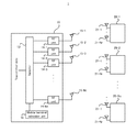
- FIG. 1 is a block diagram illustrating one example of the configuration of the MIMO wireless communication system 1 in the embodiment.
- the MIMO wireless communication system 1 in the embodiment includes a wireless base station 10 and Nu (wherein Nu is an integer of 2 or more) mobile terminals 20 (i.e. a mobile terminal 20 - 1 to a mobile terminal 20 -Nu).
- Nu is an integer of 2 or more
- the wireless base station 10 in a down link, the wireless base station 10 is a transmitter, and the mobile terminal 20 is a receiver.
- the wireless base station 10 in an up link, the wireless base station 10 is a receiver, and the mobile terminal 20 is a transmitter.
- a wireless base station there are listed a wireless base station (i.e.
- NB Node B and eNodeB (evolved NodeB) in a mobile phone system or a mobile communication system and an access point in a wireless LAN system, as one example.
- the mobile terminal 20 there are listed a mobile phone in a mobile phone system and a client (e.g. a personal computer or the like) in a wireless LAN system, as one example.
- the wireless base station 10 includes a selector 13 ; Nt (wherein Nt is an integer of 2 or more) RF units 14 (i.e. a RF unit 14 - 1 to a RF unit 14 -Nt); Nt antennas 15 (i.e. an antenna 15 - 1 to an antenna 15 -Nt); and a mobile terminal selection unit 16 .
- Each of the Nu mobile terminals 20 includes Nr (wherein Nr is an integer of 1 or more) antennas 21 (i.e. an antenna 21 - 1 to an antenna 21 -Nr).
- each of the Nu mobile terminals 20 may includes the same number of antennas 21 , or the different number of antennas 21 .
- each of the Nu mobile terminals 20 includes the Nr antennas 21 - 1 to 21 -Nr.
- the selector 13 sorts data to be transmitted to the Nu mobile terminals 20 , into the Nt antennas 15 - 1 to 15 -Nt. More specifically, the selector 13 supplies, to the Nt antennas 15 - 1 to 15 -Nt, the data to be transmitted to at least one mobile terminal 20 which is selected as a data-transmission-destination by the mobile terminal selection unit 16 , out of the data to be transmitted to the Nu mobile terminal 20 - 1 to 20 -Nu.
- the data sorted by the selector 13 is transmitted to the mobile terminal 20 via the antennas 15 - 1 to 15 -Nt after a mobile transmission process is performed by the RF units 14 - 1 to 14 -Nt.
- Each of the mobile terminals 20 receives the data to be transmitted from the wireless base station 10 via respective one of the antennas 21 - 1 to 21 -Nr.
- the mobile terminal selection unit 16 selects the mobile terminal 20 which is the data-transmission-destination (or a communication-target), by an operation described later.
- the mobile terminal selection unit 16 preferably selects the mobile terminal 20 such that the total number of the antennas 21 provided for the selected mobile terminal 20 is equal to or less than the total number of the antennas 15 provided for the wireless base station 10 .
- the operation of selecting the mobile terminal 20 may be performed in any timing, periodically or non-periodically.
- the mobile terminal selection unit 16 preferably receives various control data, which may be used to calculate a channel capacity or channel estimation, from the mobile terminal 20 .
- the mobile terminal selection unit 16 preferably obtains the various control data from an internal processing circuit provided for the wireless base station 10 .
- FIG. 2 is a flowchart illustrating a flow of the first operation example of the wireless base station 10 .
- H(j) denotes a channel matrix between the wireless base station 10 and the mobile terminal 20 - j .
- H(j) denotes a channel matrix between the Nt antennas 15 - 1 to 15 -Nt provided for the wireless base station 10 and the Nr antennas 21 - 1 to 21 -Nr provided for the mobile terminal 20 - j .
- ⁇ denotes a value obtained by dividing the number Nt of the antennas 15 - 1 to 15 -Nt provided for the wireless base station 10 , by a signal-to-noise ratio ⁇ (i.e. ⁇ denotes Nt/ ⁇ ).
- I Nr denotes an identity matrix whose number of the rows is Nr.
- the mobile terminal selection unit 16 selects the mobile terminal 20 -J which realizes the maximum entire capacity detG(j) of the channel capacity in the virtual MIMO communication system including the wireless base station 10 and the mobile terminal 20 - j , for each of all the mobile terminals (i.e. users) 20 - j which belong to the set ⁇ (step S 121 ). In other words, the mobile terminal selection unit 16 selects the mobile terminal 20 -J which satisfies an equation 4.
- the mobile terminal selection unit 16 performs an initialization operation for the operation of selecting the mobile terminal 20 (step S 122 ). Specifically, the mobile terminal selection unit 16 sets the channel matrix H(J) of the mobile terminal 20 -J selected in the step S 121 , to an initial value H 1 of a channel matrix set H n .
- the channel matrix set H 1 indicates the channel matrix of all the selected mobile terminals 20 .
- the inverse matrix B n is an inverse matrix which reflects all the selected mobile terminals 20 .
- the mobile terminal selection unit 16 removes the mobile terminal 20 -J selected in the step S 121 from the set ⁇ .
- the mobile terminal selection unit 16 sets a variable n to 1 (step S 123 ).
- the variable n indicates the number of the selected mobile terminals 20 .
- the mobile terminal selection unit 16 calculates a matrix C 2 (j) illustrated in an equation 5, for each of the mobile terminals (users) 20 - j which belong to the set ⁇ initialized in the step S 122 (step S 124 ).
- the determinant of the matrix C 2 (j) denotes an increment amount of the channel capacity which is caused by newly adding the mobile terminal 20 - j to the virtual MIMO communication system including the wireless base station 10 and the selected mobile terminal 20 .
- the determinant of the matrix C 2 (j) denotes an added capacity. Therefore, the mobile terminal selection unit 16 may calculate the increment amount of the channel capacity (i.e.
- U 2 (j) and U 1 (j) are matrices defined by an equation 6 and an equation 7, respectively.
- U 2 ( j ) U 1 ( j ) B n [Equation 6]
- U 1 ( j ) H ( j ) H n H [Equation 7]
- the mobile terminal selection unit 16 selects the mobile terminal 20 -J which realizes the maximum added capacity detC 2 (j) (step S 125 ). In other words, the mobile terminal selection unit 16 selects the mobile terminal 20 -J which satisfies an equation 8.
- the mobile terminal selection unit 16 updates the channel matrix set H n , the inverse matrix B n , and the set ⁇ described above, in accordance with the selection of the mobile terminal 20 -J in the step S 125 (step S 126 ). Specifically, the mobile terminal selection unit 16 sets a new matrix in which the channel matrix set H n before the updating and the channel matrix H(J) of the mobile terminal 20 -J selected in the step S 125 are arranged in the row direction, as the channel matrix set H n+1 after the updating. Moreover, the mobile terminal selection unit 16 calculates the inverse matrix B n+1 after the updating from the inverse matrix B n before the updating, by using an equation 9. Moreover, the mobile terminal selection unit 16 removes the mobile terminal 20 -J selected in the step S 125 from the set ⁇ .
- U 3 (J) is a matrix defined by an equation 10. Moreover, the matrices U 1 (J), U 2 (J) and C 2 (J) are already defined by the equation 7, the equation 6 and the equation 5, respectively.
- U 3 ( J ) C 2 ( J ) ⁇ 1 U 2 ( J ) [Equation 10]
- the mobile terminal selection unit 16 increments the variable n by 1 (step S 127 ). Then, the mobile terminal selection unit 16 judges whether or not the variable n is less than or equal to a value obtained by subtracting 1 from the service mobile terminal number (step S 128 ). In other words, the mobile terminal selection unit 16 judges whether or not the variable n is less than or equal to a value obtained by subtracting 1 from the number of the selectable mobile terminals 20 (step S 128 ).
- the mobile terminal selection unit 16 repeats the operations after the step S 124 .
- the mobile terminal selection unit 16 repeats the calculation of the matrix C 2 (j) or the added capacity detC 2 (j) for each of the mobile terminals (users) 20 - j which belong to the set ⁇ updated in the step S 126 , the selection of the mobile terminal 20 -J which realizes the maximum added capacity detC 2 (j), and the updating of the channel matrix set H n , the inverse matrix B n , and the set ⁇ ,
- the mobile terminal selection unit 16 designates the mobile terminals 20 selected in the step S 121 and the step S 125 as the communication-target of the wireless base station 10 (step S 129 ). In other words, the mobile terminal selection unit 16 may not designate the mobile terminals 20 which are not selected in the step S 121 and the step S 125 as the communication-target of the wireless base station 10 .
- the mobile terminal selection unit 16 sets a new matrix in which the channel matrix set H 1 before the updating and the channel matrix H( 6 ) of the newly selected mobile terminal 20 - 6 are arranged in the row direction, as the channel matrix set H 2 after the updating.
- the mobile terminal selection unit 16 sets a new matrix in which the channel matrix set H 2 before the updating and the channel matrix H( 1 ) of the newly selected mobile terminal 20 - 1 are arranged in the row direction, as the channel matrix set H 3 after the updating.
- the mobile terminal selection unit 16 sets a new matrix in which the channel matrix set H 3 before the updating and the channel matrix H( 9 ) of the newly selected mobile terminal 20 - 9 are arranged in the row direction, as the channel matrix set H 4 after the updating.
- the aforementioned explanation is about the MIMO wireless communication system 1 including the plurality of mobile terminals 20 .
- the aforementioned operations may be applied in a MIMO wireless communication system including a single mobile terminal 20 .
- the aforementioned operations may be applied to an operation of selecting the antennas 21 (in other words, an operation of selecting the antennas 21 which is the communication-target) provided for the mobile terminal 20 .
- the aforementioned “selection of the mobile terminal 20 ” is replaced by the “selection of the antenna 21 ”, and the same equations can be used in each of the equations or the like.
- FIG. 3 is a flowchart illustrating a flow of the first modified operation example in the first operation example.
- the same operations as the aforementioned operations which are already explained will carry the same step numbers, and the detailed explanation thereof will be omitted.
- the mobile terminal selection unit 16 calculates the matrix G(j) illustrated in the above equation 2 and the inverse matrix B(j) of the matrix G(j) illustrated in the above equation 3, for each of all the mobile terminals 20 - j which belong to the set ⁇ illustrated in the above equation 1 (the step S 120 ).
- the mobile terminal selection unit 16 judges whether or not there is the mobile terminal 20 to which a priority flag is applied, wherein the priority flag is to identify the mobile terminal 20 which is preferentially selected as the communication-target (step S 130 ).
- the priority flag may be applied to the mobile terminal 20 which is preset to be preferentially selected as the communication-target. Alternatively, the priority flag may be applied to the mobile terminal 20 from which the number of communication requests to the wireless base station 10 is greater than or equal to a predetermined value (or is relatively large). Of course, the priority flag may be applied to the mobile terminal 20 by other standards. Moreover, the priority flag may be stored in a memory or the like provided for the wireless base station 10 , as an internal parameter in the wireless base station 10 . Alternatively, the priority flag may be stored in a memory or the like provided for the mobile terminal and may be transmitted from the mobile terminal 20 to the wireless base station 10 as control information, as occasion demands.
- the mobile terminal selection unit 16 selects the mobile terminal 20 -J which realizes the maximum entire capacity detG(j) of the channel capacity in the virtual MIMO communication system including the wireless base station 10 and the mobile terminal 20 - j (the step S 121 ). Then, the mobile terminal selection unit 16 performs an initialization operation for the operation of selecting the mobile terminal 20 (step S 135 ).
- the mobile terminal selection unit 16 further sets a variable N to 1.
- the variable N indicates the number of the mobile terminals 20 selected before the operation of updating the inverse matrix B n .
- the mobile terminal selection unit 16 judges whether or not the number of the mobile terminal 20 to which the priority flag is applied is greater than the service mobile terminal number (step S 131 ).
- the mobile terminal selection unit 16 designates the mobile terminal 20 (mobile terminals 20 ) with higher (or relatively high) priority from among the mobile terminals 20 with each of which the priority flag is applied, as the communication-target of the wireless base station 10 (step S 134 ). In other words, the mobile terminal selection unit 16 may not designate the mobile terminal 20 (mobile terminals 20 ) with lower (or relatively low) priority, from among the mobile terminals 20 with each of which the priority flag is applied, as the communication-target of the wireless base station 10 .
- the mobile terminal selection unit 16 designates the mobile terminals 20 with each of which the priority flag is applied, as the communication-target of the wireless base station 10 (step S 134 ). In other words, the mobile terminal selection unit 16 may not designate the mobile terminal 20 except the mobile terminals 20 with each of which the priority flag is applied, as the communication-target of the wireless base station 10 .
- the priority flag may include information by which the degree (high or low) of the priority can be judged.
- the priority flag may include information which indicates the degree (high or low) of the priority by binary values (e.g. “high (H)” and “low (L)”) or multiple values.
- the priority flag may include the number of the communication requests for the wireless base station 10 , as the information which indicates the degree (high or low) of the priority. In this case, if the number of the communication requests is relatively large (or greater than a predetermined value), it may be judged that the priority is relatively high.
- the priority flag may be also included in the priority flag.
- the mobile terminal selection unit 16 selects the mobile terminals 20 with each of which the priority flag is applied (step S 132 ). For example, if the priority flag is applied to x (wherein x is an integer satisfying 1 ⁇ x ⁇ Nu) mobile terminals 20 -J 1 , 20 -J 2 , . . . , 20 -Jx out of the Nu mobile terminals 20 , the mobile terminal selection unit 16 selects the x mobile terminals 20 -J 1 , 20 -J 2 , . . . , 20 -Jx.
- the mobile terminal selection unit 16 performs an initialization operation for the operation of selecting the mobile terminal 20 (step S 133 ). Specifically, the mobile terminal selection unit 16 sets a matrix in which the channel matrix H(J 1 ), H(J 2 ), . . . , and H(Jx) of the mobile terminals 20 -J 1 , 20 -J 2 , . . . , and 20 -Jx selected in the step S 132 are arranged in the row direction, to the initial value H 1 of the channel matrix set H n of all the selected mobile terminals 20 . Moreover, the mobile terminal selection unit 16 sets the inverse matrix of the mobile terminals 20 -J 1 , 20 -J 2 , . . .
- the mobile terminal selection unit 16 removes the mobile terminals 20 -J 1 , 20 -J 2 , . . . , and 20 -Jx selected in the step S 132 from the set ⁇ . Moreover, the mobile terminal selection unit 16 sets the number x of the mobile terminals 20 selected in the step S 132 , to the variable N.
- the mobile terminal selection unit 16 sets the variable n to 1 (the step S 123 ).
- the variable n indicates the number of the selected mobile terminals 20 .
- the mobile terminal selection unit 16 calculates the matrix C 2 (j) illustrated in the above equation 5 or the added capacity detC 2 (j), for each of the mobile terminals 20 - j which belong to the set ⁇ initialized in the step S 133 or the step S 135 (the step S 124 ).
- the mobile terminal selection unit selects the mobile terminal 20 -J which realizes the maximum added capacity detC 2 (j) (the step S 125 ).
- the mobile terminal selection unit 16 updates the channel matrix set H n , the inverse matrix B n , and the set ⁇ described above, in accordance with the selection of the mobile terminal 20 -J in the step S 125 (the step S 126 ).
- the mobile terminal selection unit 16 increments the variable n by 1 (the step S 127 ). Then, the mobile terminal selection unit 16 judges whether or not the variable n is less than or equal to a value obtained by subtracting the variable N from the service mobile terminal number (i.e. the number of the selectable mobile terminals 20 ) (step S 136 ).
- the mobile terminal selection unit 16 repeats the operations after the step S 124 .
- the mobile terminal selection unit 16 designates the mobile terminals 20 selected in the step S 121 or the step S 132 and the step S 125 , as the communication-target of the wireless base station 10 (the step S 129 ). In other words, the mobile terminal selection unit 16 may not designate the mobile terminals 20 which are not selected in the step S 121 , the step S 132 and the step S 125 , as the communication-target of the wireless base station 10 .
- the first modified operation example in the first operation example it is possible to preferably receive the same effects as those received by the first operation example described above.
- the communication-target it is possible to ensure the communication with the part of the mobile terminals 20 .
- FIG. 4 is a flowchart illustrating a flow of the second modified operation example in the first operation example.
- the same operations as the aforementioned operations which are already explained will carry the same step numbers, and the detailed explanation thereof will be omitted.
- the mobile terminal selection unit 16 judges whether or not there is the mobile terminal 20 to which the priority flag is applied (the step S 130 ).
- the mobile terminal selection unit 16 sets the variable N to 1 (step S 141 ).
- the mobile terminal selection unit 16 judges whether or not the number of the mobile terminal 20 to which the priority flag is applied is greater than the service mobile terminal number (the step S 131 ).
- the mobile terminal selection unit 16 designates the mobile terminal 20 (mobile terminals 20 ) with higher (or relatively high) priority from among the mobile terminals 20 to each of which the priority flag is applied, as the communication-target of the wireless base station 10 (the step S 134 ). Alternatively, the mobile terminal selection unit 16 designates the mobile terminals 20 to each of which the priority flag is applied, as the communication-target of the wireless base station 10 (the step S 134 ).
- the mobile terminal selection unit 16 selects the mobile terminals 20 to each of which the priority flag is applied (the step S 132 ). Then, the mobile terminal selection unit 16 performs an initialization operation for the operation of selecting the mobile terminal 20 (step S 140 ). Specifically, the mobile terminal selection unit 16 removes the mobile terminals 20 -J 1 , 20 -J 2 , . . . , and 20 -Jx selected in the step S 132 from the set ⁇ . Moreover, the mobile terminal selection unit 16 sets the number of the mobile terminals 20 selected in the step S 132 , to the variable N.
- the mobile terminal selection unit 16 calculates the matrix G(j) illustrated in the above equation 2 and the inverse matrix B(j) of the matrix G(j) illustrated in the above equation 3, for each of all the mobile terminals 20 - j which belong to the set ⁇ (the step S 120 ).
- the mobile terminal selection unit 16 calculates the matrix G(j) and the inverse matrix B(j), for each of the other mobile terminals 20 except the mobile terminals 20 selected in the step S 132 .
- the mobile terminal selection unit 16 calculates the matrix G(j) and the inverse matrix B(j), for each of all the mobile terminals 20 provided for the MIMO wireless communication system 1 .
- the mobile terminal selection unit 16 selects the mobile terminal 20 -J which realizes the maximum entire capacity detG(j) of the channel capacity in the virtual MIMO communication system including the wireless base station 10 and the mobile terminal 20 - j (the step S 121 ). Then, the mobile terminal selection unit 16 performs the initialization operation for the operation of selecting the mobile terminal 20 (the step S 122 ). After the step S 122 , the operations from the step S 124 to the step S 127 , the step S 129 and the step S 136 are performed even in the second modified operation example, as in the first modified operation example.
- the second modified operation example in the first operation example it is possible to preferably receive the same effects as those received by the first modified operation example in the first operation example described above.
- FIG. 5 is a flowchart illustrating a flow of the second operation example of the wireless base station 10 .
- the same operations as the aforementioned operations which are already explained will carry the same step numbers, and the detailed explanation thereof will be omitted.
- the mobile terminal selection unit 16 selects the mobile terminal 20 -J which realizes the maximum entire capacity detG(j), instead of the operation of selecting the mobile terminal 20 -J which realizes the maximum added capacity detC 2 (j) in the first operation example (refer to the step S 124 and the step S 125 in FIG. 2 ). More specifically, as illustrated in FIG. 5 , in the second operation example, the mobile terminal selection unit 16 performs the operations from the step S 120 to the step S 123 , as in the first operation example.
- the mobile terminal selection unit 16 calculates the inverse matrix B n+1 (j) by using the updating equation of the inverse matrix B n illustrated in the above equation 9, for each of the mobile terminals (users) 20 - j which belong to the set ⁇ initialized in the step S 122 (step S 150 ). Then, the mobile terminal selection unit 16 selects the mobile terminal 20 -J which realizes the maximum entire capacity detG(j) (step S 151 ). In other words, the mobile terminal selection unit 16 selects the mobile terminal 20 -J which satisfies an equation 11.
- step S 151 even in the second operation example, the operations from the step S 126 to the step S 129 are performed as in the first operation example.
- the second operation example as in the first operation example, it is possible to reduce the processing load for the selection of the mobile terminals 20 which are the communication-targets. In other words, according to the second operation example, it is possible to preferably receive the same effects as those received by the first operation example.
- the first modified operation example or the second modified operation example in the first operation example described above may be combined with the second operation example, as occasion demands.
- the operation using the priority flag may be combined with the second operation example.
- FIG. 6 is a flowchart illustrating a flow of the third operation example of the wireless base station 10 .
- the same operations as the aforementioned operations which are already explained will carry the same step numbers, and the detailed explanation thereof will be omitted.
- the mobile terminal selection unit 16 sets the variable n to 0 (step S 161 ).
- the variable n indicates the number of the selected mobile terminals 20 .
- the mobile terminal selection unit 16 calculates the inverse matrix B n+1 (j) after the updating from the inverse matrix B n before the updating, by using an equation 15, for each of all the mobile terminals 20 - j which belong to the set ⁇ (step S 162 ).
- B n+1 ( j ) B n ⁇ U ( j )( I Nr +H ( j ) U ( j )) ⁇ 1 U ( j ) H [Equation 15]
- U(j) is a matrix defined by an equation 16.
- U ( j ) B n H ( j ) H [Equation 16]
- the mobile terminal selection unit 16 selects the mobile terminal 20 -J which realizes the maximum entire capacity detG(j) (i.e. the minimum inverse detB n+1 (j) of the entire capacity) (step S 163 ). In other words, the mobile terminal selection unit 16 selects the mobile terminal 20 -J which satisfies an equation 17. Alternatively, the mobile terminal selection unit 16 may select the mobile terminal 20 -J which realizes the minimum mean square error of the inverse matrix B n+1 (j) (step S 163 ). In other words, the mobile terminal selection unit 16 may select the mobile terminal 20 -J which satisfies an equation 18.
- J arg ⁇ ⁇ min j ⁇ ⁇ ⁇ det ⁇ ( B n + 1 ⁇ ( j ) ) [ Equation ⁇ ⁇ 17 ]
- J arg ⁇ ⁇ min j ⁇ ⁇ ⁇ trace ⁇ ( B n + 1 ⁇ ( j ) ) [ Equation ⁇ ⁇ 18 ]
- the mobile terminal selection unit 16 updates the channel matrix set H n , the inverse matrix B n , and the set ⁇ described above, in accordance with the selection of the mobile terminal 20 -J in the step S 163 (step S 164 ). Specifically, the mobile terminal selection unit 16 sets a new matrix in which the channel matrix set H n before the updating and the channel matrix H(J) of the mobile terminal 20 -J selected in the step S 163 are arranged in the row direction, as the channel matrix set H n+1 after the updating. Moreover, the mobile terminal selection unit 16 calculates the inverse matrix B n+1 after the updating from the inverse matrix B n before the updating, by using an equation 19 (which is substantially the same as the equation 15).
- the mobile terminal selection unit 16 removes the mobile terminal 20 -J selected in the step S 163 from the set ⁇ .
- B n+1 ( J ) B n ⁇ U ( J )( I Nr +H ( J ) U ( J )) ⁇ 1 U ( J ) H [Equation 19]
- the mobile terminal selection unit 16 increments the variable n by 1 (the step S 127 ). Then, the mobile terminal selection unit 16 judges whether or not the variable n is less than or equal to the value obtained by subtracting 1 from the service mobile terminal number (the step S 128 ).
- the mobile terminal selection unit 16 repeats the operations after the step S 162 .
- the mobile terminal selection unit 16 repeats the calculation of the inverse matrix B n+1 (j) after the updating for each of the mobile terminals 20 - j which belong to the set ⁇ updated in the step S 164 , the selection of the mobile terminal 20 -J which realizes the minimum inverse detB n+1 (j) of the entire capacity or which realizes the minimum mean square error traceB n+1 (j) of the inverse matrix B n+1 (j), and the updating of the channel matrix set H n , the inverse matrix B n , and the set ⁇ .
- the mobile terminal selection unit 16 designates the mobile terminals 20 selected in the step S 163 as the communication-target of the wireless base station 10 (the step S 129 ). In other words, the mobile terminal selection unit 16 may not designate the mobile terminals 20 which are not selected in the step S 163 as the communication-target of the wireless base station 10 .
- the third operation example as in the first operation example, it is possible to reduce the processing load for the selection of the mobile terminals 20 which are the communication-targets. In other words, according to the third operation example, it is possible to preferably receive the same effects as those received by the first operation example.
- FIG. 7 is a flowchart illustrating a flow of the first modified operation example in the third operation example.
- the same operations as the aforementioned operations which are already explained will carry the same step numbers, and the detailed explanation thereof will be omitted.
- the mobile terminal selection unit 16 performs the initialization operation for the operation of selecting the mobile terminal 20 (the step S 160 ). Then, the mobile terminal selection unit 16 judges whether or not there is the mobile terminal 20 to which the priority flag is applied (the step S 130 ).
- the mobile terminal selection unit 16 sets the variable N to 0 (step S 171 ).
- the mobile terminal selection unit 16 judges whether or not the number of the mobile terminal 20 to which the priority flag is applied is greater than the service mobile terminal number (the step S 131 ).
- the mobile terminal selection unit 16 designates the mobile terminal 20 (mobile terminals 20 ) with higher (or relatively high) priority from among the mobile terminals 20 to each of which the priority flag is applied, as the communication-target of the wireless base station 10 (the step S 134 ).
- the mobile terminal selection unit 16 selects the mobile terminals 20 to each of which the priority flag is applied (the step S 132 ). Then, the mobile terminal selection unit 16 performs an initialization operation for the operation of selecting the mobile terminal 20 (step S 172 ). Specifically, the mobile terminal selection unit 16 sets a matrix in which the channel matrices H(J 1 ), H(J 2 ), . . . , and H(Jx) of the mobile terminals 20 -J 1 , 20 -J 2 , . .
- the mobile terminal selection unit 16 sets the inverse matrix of the mobile terminals 20 -J 1 , 20 -J 2 , . . . , and 20 -Jx, calculated on the basis of the equation 19 and the matrices corresponding to the mobile terminals 20 -J 1 , 20 -J 2 , . . . , and 20 -Jx selected in the step S 132 , to the initial value B 0 of the inverse matrix B n reflecting all the selected mobile terminals 20 .
- the mobile terminal selection unit 16 removes the mobile terminals 20 -J 1 , 20 -J 2 , . . . , and 20 -Jx selected in the step S 132 from the set ⁇ . Moreover, the mobile terminal selection unit 16 sets the number x of the mobile terminals 20 selected in the step S 132 , to the variable N.
- the mobile terminal selection unit 16 sets the variable n to 0 (the step S 161 ).
- the variable n indicates the number of the selected mobile terminals 20 .
- the mobile terminal selection unit 16 calculates the inverse matrix B n +1 (j) after the updating from the inverse matrix B n before the updating, by using the equation 15, for each of all the mobile terminals 20 - j which belong to the set ⁇ (the step S 162 ).
- the mobile terminal selection unit 16 selects the mobile terminal 20 -J which realizes the minimum inverse detB n+1 (j) of the entire capacity (the step S 163 ).
- the mobile terminal selection unit 16 may select the mobile terminal 20 -J which realizes the minimum mean square error of the inverse matrix B n+1 (j) (the step S 163 ). Then, the mobile terminal selection unit 16 updates the channel matrix set H n , the inverse matrix B n , and the set ⁇ described above, in accordance with the selection of the mobile terminal 20 -J in the step S 163 (the step S 164 ). Then, the mobile terminal selection unit 16 increments the variable n by 1 (the step S 127 ).
- the mobile terminal selection unit 16 judges whether or not the variable n is less than or equal to the value obtained by subtracting the variable N from the service mobile terminal number (the step S 136 ).
- the mobile terminal selection unit 16 repeats the operations after the step S 162 .
- the mobile terminal selection unit 16 designates the mobile terminals 20 selected in the step S 132 and the step S 163 , as the communication-target of the wireless base station 10 (the step S 129 ).
- the first modified operation example in the third operation example it is possible to preferably receive the same effects as those received by the third operation example described above.
- the communication-target it is possible to ensure the communication with the part of the mobile terminals 20 .
- FIG. 8 is a flowchart illustrating a flow of the second modified operation example in the third operation example.
- the same operations as the aforementioned operations which are already explained will carry the same step numbers, and the detailed explanation thereof will be omitted.
- the mobile terminal selection unit 16 performs the initialization operation for the operation of selecting the mobile terminal 20 (the step S 160 ). Then, the mobile terminal selection unit 16 judges whether or not there is the mobile terminal 20 to which the priority flag is applied (the step S 130 ).
- the mobile terminal selection unit 16 sets the variable N to 0 (the step S 171 ).
- the mobile terminal selection unit 16 judges whether or not the number of the mobile terminal 20 to which the priority flag is applied is greater than the service mobile terminal number (the step S 131 ).
- the mobile terminal selection unit 16 designates the mobile terminal 20 (mobile terminals 20 ) with higher (or relatively high) priority from among the mobile terminals 20 to each of which the priority flag is applied, as the communication-target of the wireless base station 10 (the step S 134 ).
- the mobile terminal selection unit 16 selects the mobile terminals 20 to each of which the priority flag is applied (the step S 132 ). Then, the mobile terminal selection unit 16 performs the initialization operation for the operation of selecting the mobile terminal 20 (the step S 140 ). Specifically, the mobile terminal selection unit 16 sets the set ⁇ and the variable N, as in the second modified operation example in the first operation example.
- step S 171 or the step S 140 After the operation in the step S 171 or the step S 140 , the operations from the step S 161 to the step S 164 , the step S 127 , the step S 136 and the step S 129 are performed, as in the first modified operation example in the third operation example.
- the second modified operation example in the third operation example it is possible to preferably receive the same effects as those received by the first modified operation example in the third operation example described above.
- FIG. 9 is a flowchart illustrating a flow of the fourth operation example of the wireless base station 10 .
- the same operations as the aforementioned operations which are already explained will carry the same step numbers, and the detailed explanation thereof will be omitted.
- the mobile terminal selection unit 16 may set the initial value B K of the inverse matrix B n by using a recursive equation, as in the first operation example or the like. Specifically, the mobile terminal selection unit 16 firstly defines H n which is the channel matrix set between all the mobile terminals 20 - 1 to 20 -Nu and n antennas 15 from among the Nt antennas 15 - 1 to 15 -Nt provided for the wireless base station 10 , and then defines the inverse matrix B n related to the channel matrix set H n as illustrated in an equation 21.
- B n ( H n H H n + ⁇ I n ) ⁇ 1 [Equation 21]
- the mobile terminal selection unit 16 updates the inverse matrix B n , which is an inverse matrix obtained when the antenna 15 - j is sequentially added to the virtual MIMO wireless communication system including all the mobile terminals 20 - 1 to 20 -Nu and the Nt antennas 15 - 1 to 15 -Nt, by using a recursive equation illustrated in an equation 22.
- the resulting inverse matrix B n is the initial value B K of the inverse matrix B n set in the step S 190 .
- B n + 1 [ B n + u 3 ⁇ ⁇ ( j ) ⁇ u 3 ⁇ ( j ) H d ⁇ ( j ) - u 3 ⁇ ⁇ ( j ) - u 3 ⁇ ( j ) H d ⁇ ( j ) ] [ Equation ⁇ ⁇ 22 ]
- u 3 (j) and d(j) are matrices defined by an equation 23 and an equation 24, respectively.
- u 1 (j), u 2 (j) and g(j) are matrices defined by an equation 25, an equation 26, and an equation 27, respectively.
- u 1 ( j ) H n H h ( j ) [Equation 25]
- u 2 ( j ) B n u 1 ( j ) [Equation 26]
- g ( j ) h ( j ) H h ( j )+ ⁇ [Equation 27]
- h(j) is the channel matrix of the added antenna 15 - j.
- the mobile terminal selection unit 16 sets the variable n to Nu- 1 (step S 191 ). Then, the mobile terminal selection unit 16 calculates the inverse matrix B n (j) after the updating from the inverse matrix B n+1 before the updating, by using an equation 28, for each of all the mobile terminals 20 - j which belong to the set ⁇ (step S 192 ).
- B n ( j ) B n+1 +V ( j )( I Nr ⁇ H ( j ) V ( j )) ⁇ 1 V ( j ) H [Equation 28]
- V(j) is a matrix defined by an equation 29.
- V ( j ) B n+1 H ( j ) H [Equation 29]
- the mobile terminal selection unit 16 selects the mobile terminal 20 -J which satisfies a predetermined selection criterion (step S 193 ).
- the mobile terminal 20 selected in the step S 193 is the mobile terminal 20 which is not the communication-target of the wireless base station 10 .
- the mobile terminal selection unit 16 may select the mobile terminal 20 -J which realizes the minimum mean square error of the inverse matrix B n (j) obtained by removing the mobile terminal 20 - j from the virtual MIMO communication system.
- the mobile terminal selection unit 16 may select the mobile terminal 20 -J which realizes the minimum product of the on-diagonal elements of the inverse matrix B n (j) (in other words, which realizes the minimum inverse of the product of the signal-to-noise ratios).
- the mobile terminal selection unit 16 may select the mobile terminal 20 -J which realizes the maximum sum of the inversed on-diagonal elements of the inverse matrix B n (j).
- the mobile terminal selection unit 16 may select the mobile terminal 20 -J which realizes the minimum determinant of the inverse matrix B n (j) (i.e. which realizes the maximum entire capacity).
- the mobile terminal selection unit 16 may select the mobile terminal 20 -J which realizes the minimum combination of the maximum values of the on-diagonal elements of the inverse matrix B n (j) (i.e. which realizes the minimum block error rate (BER)).
- the mobile terminal selection unit 16 updates the channel matrix set H n , the inverse matrix B n , and the set ⁇ described above, in accordance with the selection of the mobile terminal 20 -J in the step S 193 (step S 194 ). Specifically, the mobile terminal selection unit 16 calculates the inverse matrix B n after the updating from the inverse matrix B n+1 before the updating, by using an equation 30 (which is substantially the same as the equation 28). Moreover, the mobile terminal selection unit 16 removes the mobile terminal 20 -J selected in the step S 193 from the set ⁇ .
- B n ( J ) B n+1 +V ( J )( I Nr ⁇ H ( J ) V ( J )) ⁇ 1 V ( J ) H [Equation 30]
- the mobile terminal selection unit 16 decrements the variable n by 1 (step S 195 ). Then, the mobile terminal selection unit 16 judges whether or not the variable n is greater than or equal to the service mobile terminal number (step S 196 ).
- the mobile terminal selection unit 16 repeats the operations after the step S 192 .
- the mobile terminal selection unit 16 repeats the calculation of the inverse matrix B n (j) after the updating for each of the mobile terminals 20 - j which belong to the set ⁇ updated in the step S 194 , the selection of the mobile terminal 20 -J which satisfies the predetermined criterion, and the updating of the inverse matrix B n and the set ⁇ .
- the mobile terminal selection unit 16 removes the mobile terminals 20 selected in the step S 193 from the communication-target of the wireless base station 10 (step S 197 ). In other words, the mobile terminal selection unit 16 designates the mobile terminals 20 which are not selected in the step S 193 as the communication-target of the wireless base station 10 .
- the fourth operation example as in the first operation example, it is possible to reduce the processing load for the selection of the mobile terminals 20 which are the communication-targets. In other words, according to the fourth operation example, it is possible to preferably receive the same effects as those received by the first operation example.
- the mobile terminals 20 which are not the communication-target it is possible to sequentially select the mobile terminals 20 which are not the communication-target (in other words, which are removed from the communication-target).
- the mobile terminals 20 which are the communication-targets can be selected more efficiently. For example, an explanation will be given on a specific example in a case where twelve mobile terminals 20 are selected from fifteen mobile terminals 20 as the communication-target (in other words, three mobile terminals 20 from among the fifteen mobile terminals 20 are removed from the communication target).
- the mobile terminals 20 which are the communication-targets can be selected more efficiently in the first to third operation examples than the fourth operation example.
- the mobile terminals 20 which are the communication-target can be selected more efficiently in the first to third operation examples than the fourth operation example.
- an explanation will be given on a specific example in a case where four mobile terminals 20 are selected from fifteen mobile terminals 20 as the communication-target (in other words, eleven mobile terminals 20 from among the fifteen mobile terminals 20 are removed from the communication target).
- FIG. 10 is a flowchart illustrating a flow of the first modified operation example in the fourth operation example.
- the same operations as the aforementioned operations which are already explained will carry the same step numbers, and the detailed explanation thereof will be omitted.
- the mobile terminal selection unit 16 judges whether or not there is the mobile terminal 20 to which the priority flag is applied (the step S 130 ).
- the mobile terminal selection unit 16 sets the variable N to 1 (the step S 141 ).
- the mobile terminal selection unit 16 judges whether or not the number of the mobile terminal 20 to which the priority flag is applied is greater than the service mobile terminal number (the step S 131 ).
- the mobile terminal selection unit 16 designates the mobile terminal 20 with higher (or relatively high) priority from among the mobile terminals 20 to each of which the priority flag is applied, as the communication-target of the wireless base station 10 (the step S 134 ).
- the mobile terminal selection unit 16 applies a non-target flag to the mobile terminals 20 to each of which the priority flag applied (step S 200 ).
- the non-target flag indicates to be removed from the selection target in the step S 193 .
- the mobile terminal selection unit 16 sets the variable N to a value obtained by subtracting 1 from the number of the mobile terminal 20 to which the on-target flag is applied in the step S 200 (step S 201 ).
- the mobile terminal selection unit 16 After the operation in the step S 141 or the step S 201 , the mobile terminal selection unit 16 performs the initialization operation for the operation of selecting the mobile terminal 20 (the step S 190 ).
- the mobile terminal selection unit 16 sets the variable n to Nu-N (step S 202 ). Then, the mobile terminal selection unit 16 calculates the inverse matrix B n (j) after the updating from the inverse matrix B n+1 before the updating, for each of the mobile terminals 20 - j which belong to the set ⁇ and to each of which the non-target flag is not applied (step S 203 ). After that, as in the fourth operation example, the operations from the step S 193 to the step S 197 are performed.
- the first modified operation example in the fourth operation example it is possible to preferably receive the same effects as those received by the fourth operation example described above.
- the communication-target it is possible to ensure the communication with the part of the mobile terminals 20 .
- FIG. 11 is a flowchart illustrating a flow of the second modified operation example in the fourth operation example.
- the same operations as the aforementioned operations which are already explained will carry the same step numbers, and the detailed explanation thereof will be omitted.
- the mobile terminal selection unit 16 judges whether or not there is the mobile terminal 20 to which the priority flag is applied (the step S 130 ).
- the mobile terminal selection unit 16 sets the variable N to 1 (the step S 141 ).
- the mobile terminal selection unit 16 judges whether or not the number of the mobile terminal 20 to which the priority flag is applied is greater than the service mobile terminal number (the step S 131 ).
- the mobile terminal selection unit 16 designates the mobile terminal 20 with higher (or relatively high) priority from among the mobile terminals 20 to each of which the priority flag is applied, as the communication-target of the wireless base station 10 (the step S 134 ).
- the mobile terminal selection unit 16 designates the mobile terminals 20 to each of which the priority flag is applied, as the mobile terminals 20 to be removed from the selection target in the step S 193 (step S 210 ). In association with the operation in the step S 210 , the mobile terminal selection unit 16 removes the mobile terminals 20 -J 1 , 20 -J 2 , . . . , and 20 -Jx designated in the step S 210 , from the set ⁇ (step S 211 ). Moreover, the mobile terminal selection unit 16 sets the variable N to a value obtained by subtracting 1 from the number x of the mobile terminals 20 designated in the step S 210 (step S 211 ).
- the mobile terminal selection unit 16 After the operation in the step S 141 or the step S 211 , the mobile terminal selection unit 16 performs the initialization operation for the operation of selecting the mobile terminal 20 (the step S 190 ). However, if the set ⁇ is already set in the step S 211 , the mobile terminal selection unit 16 may not set the set ⁇ .
- a wireless base station for performing multiple input multiple output communication with a plurality of mobile terminals
- the wireless base station including:
- a selecting unit which selects a mobile terminal, which realizes such a condition that a parameter satisfies a predetermined criterion, from the plurality of mobile terminals, the parameter being defined by an inverse matrix of a predetermined matrix which is used to calculate a channel capacity between the plurality of mobile terminals and the wireless base station;
- an updating unit which updates the inverse matrix on the basis of the selected mobile terminal every time the mobile terminal is selected by the selecting unit
- the selecting unit selecting new mobile terminal, which realizes such a condition that the parameter defined by the updated inverse matrix satisfies the predetermined criterion, from the other mobile terminals except the mobile terminal selected by the selecting unit out of the plurality of mobile terminals, every time the inverse matrix is updated by the updating unit.
- ⁇ is a value obtained by dividing the number of antennas provided for the wireless base station by a signal-to-noise ratio
- I n ⁇ Nr is an identity matrix whose number of the rows is the number of antennas provided for the mobile terminal Nr ⁇ n, and
- H n is a channel matrix of the selected n mobile terminals
- the updating unit obtains the updated inverse matrix B n+1 on the basis of an equation 31 when the (n+1)-th mobile terminal is newly selected by the selecting unit,
- H(k) is a channel matrix of the selected (n+1)-th mobile terminal
- the selecting unit selects the mobile terminal which realizes a maximum entire capacity before starting the update of the inverse matrix
- H(k) is a channel matrix of the selected mobile terminal.
- the selecting unit selects the mobile terminal which realizes (i) a maximum entire capacity of the channel capacity which is obtained by individually adding each of the other mobile terminals, or (ii) a maximum added capacity which is added to the channel capacity by individually adding each of the other mobile terminals.
- the entire capacity is an inverse of a determinant of the inverse matrix
- the added capacity is a determinant of a matrix C 2 .
- ⁇ is a value obtained by dividing the number of antennas provided for the wireless base station by a signal-to-noise ratio
- I Nr is an identity matrix whose number of the rows is the number of antennas provided for the mobile terminal Nr,
- I Nt is an identity matrix whose number of the rows is the number of antennas provided for the wireless base station Nt, and
- H n is a channel matrix of the selected n mobile terminals
- H(k) is a channel matrix of the selected (n+1)-th mobile terminal
- ⁇ is a signal-to-noise ratio
- the selecting unit selects the mobile terminal which realizes (i) a maximum entire capacity of the channel capacity obtained by individually adding each of the other mobile terminals, or (ii) a minimum mean square error of the inverse matrix corresponding to each of the other mobile terminals.
- the entire capacity is an inverse of a determinant of the inverse matrix
- the mean square error is a sum of on-diagonal elements of the inverse matrix.
- the selecting unit selects the mobile terminal as a mobile terminal which is a communication-target of the wireless base station.
- ⁇ is a value obtained by dividing the number of antennas provided for the wireless base station by a signal-to-noise ratio
- I Nt is an identity matrix whose number of the rows is the number of antennas provided for the wireless base station Nt, and
- H K is a channel matrix of the plurality of mobile terminals
- H(k) is a channel matrix of the selected mobile terminal
- V B n+1 H(k)H.
- the selecting device selects the mobile terminal which realizes (i) a minimum mean square error of the inverse matrix obtained by individually removing each of the other mobile terminals, (ii) a maximum sum or maximum product of signal-to-noise ratios obtained by individually removing each of the other mobile terminals, or (iii) a minimum entire capacity of the channel capacity obtained by individually removing each of the other mobile terminals.
- the mean square error is a sum of on-diagonal elements of the inverse matrix
- the sum of the signal-to-noise ratios is a value obtained by adding the inversed on-diagonal elements of the inverse matrix
- the sum of the signal-to-noise ratios is an inverse of the product of the on-diagonal elements of the inverse matrix
- the entire capacity is an inverse of a determinant of the inverse matrix.
- the selecting unit selects the mobile terminal as a mobile terminal to be removed from a communication-target of the wireless base station.
- the selecting unit (i) preferentially selects the mobile terminal whose selection priority is set to be relatively high and the mobile terminal from which communication requests are performed predetermined times or more, before selecting the mobile terminal on the basis of the inverse matrix, and then (ii) selects new mobile terminal, which realizes such a condition that the parameter defined by the inverse matrix satisfies the predetermined criterion, from the other mobile terminals except the preferentially selected mobile terminals.
- a method of selecting a mobile terminal in a wireless base station for performing multiple input multiple output communication with a plurality of mobile terminals
- the method includes:
- a selecting process which selects a mobile terminal, which realizes such a condition that a parameter satisfies a predetermined criterion from the plurality of mobile terminals, the parameter being defined by an inverse matrix of a predetermined matrix which is used to calculate a channel capacity between the plurality of mobile terminals and the wireless base station;
- the selecting process selecting new mobile terminal, which realizes such a condition that the parameter defined by the updated inverse matrix satisfies the predetermined criterion, from the other mobile terminals except the mobile terminal selected by the selecting process out of the plurality of mobile terminals, every time the inverse matrix is updated by the updating process.
Landscapes
- Engineering & Computer Science (AREA)
- Computer Networks & Wireless Communication (AREA)
- Signal Processing (AREA)
- Mobile Radio Communication Systems (AREA)
- Radio Transmission System (AREA)
Abstract
Description
jεΩ={1, 2, . . . , Nu} [Equation 1]
G(j)=H(j)H(j)H +γI Nr [Equation 2]
B(j)=G(j)−1=(H(j)H(j)H +γI Nr)−1 [Equation 3]
C 2(j)=G(j)−U 2(j)U 1(j)H [Equation 5]
U 2(j)=U 1(j)B n [Equation 6]
U 1(j)=H(j)H n H [Equation 7]
U 3(J)=C 2(J)−1 U 2(J) [Equation 10]
H0={ } [Equation 12]
B0=ρINt [Equation 13]
jεΩ={1, 2, . . . , Nu} [Equation 14]
B n+1(j)=B n −U(j)(I Nr +H(j)U(j))−1 U(j)H [Equation 15]
U(j)=B n H(j)H [Equation 16]
B n+1(J)=B n −U(J)(I Nr +H(J)U(J))−1 U(J)H [Equation 19]
B K=(H K H H K +γI Nt)−1 [Equation 20]
B n=(H n H H n +γI n)−1 [Equation 21]
u 1(j)=H n H h(j) [Equation 25]
u 2(j)=B n u 1(j) [Equation 26]
g(j)=h(j)H h(j)+γ [Equation 27]
B n(j)=B n+1 +V(j)(I Nr −H(j)V(j))−1 V(j)H [Equation 28]
V(j)=B n+1 H(j)H [Equation 29]
B n(J)=B n+1 +V(J)(I Nr −H(J)V(J))−1 V(J)H [Equation 30]
-
- U1=H(k)Hn H,
- U2=U1Bn,
- U3=C2 −1U2, and
- C2=G(k)−U2U1 H=(H(k)H(k)H+γI)−U2U1 H.
B n+1 =B n −U(I Nr +H(k)U)−1UH, [Equation 32]
B n =B n+1 +V(I Nr −H(k)V)−1 V H, [Equation 33]
Claims (10)
B n+1 =B n −U(I Nr +H(k)U)−1 U H, [Equation 2]
B n =B n+1 +V(I Nr −H(k)V)−1 V H, [Equation 3]
Applications Claiming Priority (2)
| Application Number | Priority Date | Filing Date | Title |
|---|---|---|---|
| JP2010-021232 | 2010-02-02 | ||
| JP2010021232A JP5434639B2 (en) | 2010-02-02 | 2010-02-02 | Wireless base station and communication method |
Publications (2)
| Publication Number | Publication Date |
|---|---|
| US20110190020A1 US20110190020A1 (en) | 2011-08-04 |
| US8565800B2 true US8565800B2 (en) | 2013-10-22 |
Family
ID=44342119
Family Applications (1)
| Application Number | Title | Priority Date | Filing Date |
|---|---|---|---|
| US12/987,126 Expired - Fee Related US8565800B2 (en) | 2010-02-02 | 2011-01-09 | Wireless base station, and method of selecting mobile terminal |
Country Status (2)
| Country | Link |
|---|---|
| US (1) | US8565800B2 (en) |
| JP (1) | JP5434639B2 (en) |
Families Citing this family (1)
| Publication number | Priority date | Publication date | Assignee | Title |
|---|---|---|---|---|
| JP5488016B2 (en) * | 2009-03-30 | 2014-05-14 | 富士通株式会社 | Wireless communication method, wireless communication system, and wireless communication apparatus |
Citations (3)
| Publication number | Priority date | Publication date | Assignee | Title |
|---|---|---|---|---|
| JP2007020188A (en) | 2005-07-06 | 2007-01-25 | Ntt Docomo Inc | MIMO communication system and user scheduling method |
| US20080037671A1 (en) * | 2006-08-10 | 2008-02-14 | Samsung Electronics Co., Ltd. | Apparatus and method for low-complexity scheduling in multi-user mimo system |
| US20090016460A1 (en) * | 2007-05-29 | 2009-01-15 | Samsung Electronics Co., Ltd. | Apparatus and method for beamforming with limited feedforward channel in multiple input multiple output wireless communication system |
Family Cites Families (2)
| Publication number | Priority date | Publication date | Assignee | Title |
|---|---|---|---|---|
| KR100575993B1 (en) * | 2003-08-07 | 2006-05-02 | 삼성전자주식회사 | Scheduling method and apparatus for multi-user in mobile communication system using multiple transmit / receive antenna |
| JP2008035257A (en) * | 2006-07-28 | 2008-02-14 | Tokyo Institute Of Technology | Scheduling method, apparatus and control program for wireless communication system |
-
2010
- 2010-02-02 JP JP2010021232A patent/JP5434639B2/en not_active Expired - Fee Related
-
2011
- 2011-01-09 US US12/987,126 patent/US8565800B2/en not_active Expired - Fee Related
Patent Citations (3)
| Publication number | Priority date | Publication date | Assignee | Title |
|---|---|---|---|---|
| JP2007020188A (en) | 2005-07-06 | 2007-01-25 | Ntt Docomo Inc | MIMO communication system and user scheduling method |
| US20080037671A1 (en) * | 2006-08-10 | 2008-02-14 | Samsung Electronics Co., Ltd. | Apparatus and method for low-complexity scheduling in multi-user mimo system |
| US20090016460A1 (en) * | 2007-05-29 | 2009-01-15 | Samsung Electronics Co., Ltd. | Apparatus and method for beamforming with limited feedforward channel in multiple input multiple output wireless communication system |
Also Published As
| Publication number | Publication date |
|---|---|
| JP2011160269A (en) | 2011-08-18 |
| JP5434639B2 (en) | 2014-03-05 |
| US20110190020A1 (en) | 2011-08-04 |
Similar Documents
| Publication | Publication Date | Title |
|---|---|---|
| US8086273B2 (en) | Wireless communication method, wireless communication system, and wireless communication apparatus | |
| US8774302B2 (en) | Wireless communication system and wireless communication method | |
| US9401756B2 (en) | Method for configuring multiple antennas and related wireless communication device | |
| US20040235433A1 (en) | Determining transmit diversity order and branches | |
| WO2019047940A1 (en) | Reference signal configuration, information transmission, and information receiving methods and device | |
| US8743755B2 (en) | Downlink resource scheduling method and transmission end for multiple-input multiple-output beam-forming system | |
| US8855571B2 (en) | Radio communication apparatus, system, and method | |
| US20200274591A1 (en) | Remote radio head, beamforming method and storage medium | |
| JP6663256B2 (en) | Wireless communication system and management device | |
| US7940690B2 (en) | Apparatus and method for determining transmission mode in wireless communication system | |
| US20150173090A1 (en) | Distributed multi-cell multi-user beamforming method, transmitter and relevant system | |
| US20120014469A1 (en) | Wireless communication system, device and method | |
| US8565800B2 (en) | Wireless base station, and method of selecting mobile terminal | |
| JP5331036B2 (en) | Wireless communication terminal and antenna impedance control method | |
| EP2112771A1 (en) | Adaptive MIMO mode selection method and apparatus thereof | |
| US11677452B2 (en) | Method and apparatus for transmitting and receiving signal for terminal-centric cooperative transmission | |
| CN102104406B (en) | Method and system for switching beam forming and MIMO (Multi-Input Multi-Output) beam forming | |
| EP4358428A2 (en) | Wireless communication device and method employing channel state information compression | |
| Benkhelifa et al. | A thresholding-based antenna switching in MIMO cognitive radio networks with SWIPT-enabled secondary receiver | |
| JP7206734B2 (en) | BASE STATION DEVICE, SELECTION METHOD AND WIRELESS SYSTEM | |
| JP2015220554A (en) | Spatial multiplexing scheduling method, base station apparatus, and program | |
| KR101482925B1 (en) | Zero-forcing Beamformer Design Device and Method in MISO Broadcast Channel Based on k-regularity | |
| KR101827930B1 (en) | Method for spectrum sharing by frequency hopping and communication system using the same | |
| US8565144B2 (en) | Scheduling apparatus and method of relay-based network | |
| WO2020194428A1 (en) | Lower level radio base station and method for controlling number of spatial multiplex streams |
Legal Events
| Date | Code | Title | Description |
|---|---|---|---|
| AS | Assignment |
Owner name: FUJITSU LIMITED, JAPAN Free format text: ASSIGNMENT OF ASSIGNORS INTEREST;ASSIGNOR:ZHOU, LIANG;REEL/FRAME:025718/0173 Effective date: 20101208 |
|
| STCF | Information on status: patent grant |
Free format text: PATENTED CASE |
|
| FEPP | Fee payment procedure |
Free format text: PAYOR NUMBER ASSIGNED (ORIGINAL EVENT CODE: ASPN); ENTITY STATUS OF PATENT OWNER: LARGE ENTITY |
|
| FEPP | Fee payment procedure |
Free format text: PAYER NUMBER DE-ASSIGNED (ORIGINAL EVENT CODE: RMPN); ENTITY STATUS OF PATENT OWNER: LARGE ENTITY Free format text: PAYOR NUMBER ASSIGNED (ORIGINAL EVENT CODE: ASPN); ENTITY STATUS OF PATENT OWNER: LARGE ENTITY |
|
| FPAY | Fee payment |
Year of fee payment: 4 |
|
| FEPP | Fee payment procedure |
Free format text: MAINTENANCE FEE REMINDER MAILED (ORIGINAL EVENT CODE: REM.); ENTITY STATUS OF PATENT OWNER: LARGE ENTITY |
|
| LAPS | Lapse for failure to pay maintenance fees |
Free format text: PATENT EXPIRED FOR FAILURE TO PAY MAINTENANCE FEES (ORIGINAL EVENT CODE: EXP.); ENTITY STATUS OF PATENT OWNER: LARGE ENTITY |
|
| STCH | Information on status: patent discontinuation |
Free format text: PATENT EXPIRED DUE TO NONPAYMENT OF MAINTENANCE FEES UNDER 37 CFR 1.362 |
|
| FP | Lapsed due to failure to pay maintenance fee |
Effective date: 20211022 |