US856489A - Car-coupling. - Google Patents
Car-coupling. Download PDFInfo
- Publication number
- US856489A US856489A US32635106A US1906326351A US856489A US 856489 A US856489 A US 856489A US 32635106 A US32635106 A US 32635106A US 1906326351 A US1906326351 A US 1906326351A US 856489 A US856489 A US 856489A
- Authority
- US
- United States
- Prior art keywords
- knuckle
- latch
- pin
- pivot
- coupling
- Prior art date
- Legal status (The legal status is an assumption and is not a legal conclusion. Google has not performed a legal analysis and makes no representation as to the accuracy of the status listed.)
- Expired - Lifetime
Links
Images
Classifications
-
- B—PERFORMING OPERATIONS; TRANSPORTING
- B61—RAILWAYS
- B61G—COUPLINGS; DRAUGHT AND BUFFING APPLIANCES
- B61G3/00—Couplings comprising mating parts of similar shape or form which can be coupled without the use of any additional element or elements
- B61G3/04—Couplings comprising mating parts of similar shape or form which can be coupled without the use of any additional element or elements with coupling head having a guard arm on one side and a knuckle with angularly-disposed nose and tail portions pivoted to the other side thereof, the nose of the knuckle being the coupling part, and means to lock the knuckle in coupling position, e.g. "A.A.R." or "Janney" type
Definitions
- This invention relates to car couplings of the knuckle type, and has for its object to provide the knuckle with abutting shoulders back of the pivot, ⁇ extending both upward.
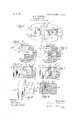
- Figure 1 shows in plan view a car coupling embodying this invention.
- Fig. 2 is a scctional detail of one of the corpling members,
- FIG. 3 is a similar ⁇ sectional detail showing the interlocking member swung into locking'p'osition.
- Fig. 4 is a vertical section of one of the coupling memberst'aken on the dotted line 4 4, Fig. 2.
- Fig 5 is a vertical section of one of the coupling members taken on thedotted line 5-5
- Fig. 6 is a vertical section of one of the coupling mem# bers taken ⁇ on the dotted line 6*(3, Fig. 3.
- - Fig. 7 is a perspective view ofthe interlock- ⁇ .the guard a2 are all as u ual.
- the draw bar a and raw head. a having The knuckle,
- the end of the latch-engaging portion a4 of the knuckle is formed with abutting shoulders b, b, on its upper and under sides, back of the slot a, the engaging or acting faces of which are made straight from the outer side of the knuckle to a point near the inner side thereof and then curved at the inner side thereof.
- the knuckle-receiving recess in the head is formed with two like vbosses above and below, one extending downwardand the other upward, and said bosses enter the spaces in the upper and under sldes of the knuckle between the guard-engaging portion a3 and the latch-engaging portion a and the circular li'ole which is provided for the pivot-pin a5 extends through both of said bosses.
- the rear walls of both bosses serve as abutments c, c,- against which the shoulderszbyb, respectively engagc when the knuckle is moved into interlocking position. yThese 'abutf ments. are, therefore, located back of the pivot-pins af".
- the abutments c, c are shaped to correspond to the shape of the abutting shoulders and when so shaped it will be seen that as the knuckle is swung on its pivot into locking position. it will be moved rearward a short distance so that the strain will he resisted by the ab'tments-in the head, and the pivot pin will be abso, lutely relieved of all strain. In this ⁇ type or; class of coupling. this is an important feature, vA as ordinarily, the pivot pin resists the strain, and it occasionally happens that .the upper or under support for said pin is broken off,4 or the pin itself is broken, a result which is'not liable to happen with the construction herein shown. Furthermore, .the abutting shoulders and abutnients are formed of large area and therefore capable of resisting a much greater strain than the pin.
- Patent is ward, and having a slot for the pivot pin, a
- a pivoted knuckle having abutting shoulders back of its pivot, extending upward and downward, the engaging faces of which are made straight from the outer side of the knuckle to a point near the inner side thereof, and then curved .at the ⁇ inner side of the knuckle, a pivot pin for the knuckle, a drawhead to which the knuckle is pivoted, having its knuckle-receiving recess formed with abutments above and below, the engaging faces of whic-h, against which the shoulders on the knuckle abut, being shaped to correspond with the shape of the engaging faces ofsaid shoulders, substantially as described.
- a pivoted knuckle on the drawhead a pivoted gravitating latch for said knuckle contained in a recess in the drawhead, a locking device for said latch comprising a pin or link pivoted to the rear side thereof and extending upward, and its upper end designed to engage a shoulder on the drawhead, said pin or link being entirely within tlie'drawhead, and means for lifting said latch, substantially as described.
- a pivoted knuckle on the drawhead a pivoted gravitating latch for said knuckle contained in a recess in the drawhead, a-locking device for said latch extending upwardly from the Frear side. thereof and situated entirely within the drawhead and means for re leasing said locking device and lifting the latch, substantially as described.
Description
N0.s56,489. Y PATENTEDJUNE11,1907.
E. F. PENDEXTER.
GAR GOUPLING.
APPLICATION FILED JULY 16.1906.
x7 MMM UNITED STATES PATENT FFTCE.
EDWARD F. PENDEXTER; OF MILFORD, MASSACHUSETTS.
oAs-oouPLlNe.
Specification of Letters Patent.
l Patented June 11, 1907.
' @Primm nur Juv 16,1906. sereine. 326.351.
This invention relates to car couplings of the knuckle type, and has for its object to provide the knuckle with abutting shoulders back of the pivot,` extending both upward.
andl downward, which areadaptedto engage abutments provided in the draw-head, ito thereby relieve the pivot pin of the severe strain to which it is ordinarily subjected; also to form said abuttingshoulders and abutments in such manner 'that the knuckle will be drawn rearwarda short, distance when swung. intolocking position, a slot being provided for the pivot pin in lieu of the hole which is usu'ally provided therefor, to'permit of such rearward movement, whereby the entire strain will be resisted by the abotments which are provided in the draw-head; also to provide a pivoted gravitating latch which holds'the knuckle in its locking posi-tion, the pivot of the latch being arranged at right angles tothe length of the head, and an in iproved locking-device being employed for I Said latch, which holds it in its locking pos1- tion, but which is adapted to'be released by the hand-lever which is. employed for lifting the latch.;
Figure 1 shows in plan view a car coupling embodying this invention. Fig. 2 is a scctional detail of one of the corpling members,
` showing the interlocking member swung open. Fig. 3 is a similar `sectional detail showing the interlocking member swung into locking'p'osition. Fig. 4 is a vertical section of one of the coupling memberst'aken on the dotted line 4 4, Fig. 2. .Fig 5 is a vertical section of one of the coupling members taken on thedotted line 5-5, Fig.` 3.- Fig. 6 is a vertical section of one of the coupling mem# bers taken`on the dotted line 6*(3, Fig. 3.
- Fig. 7 is a perspective view ofthe interlock- `.the guard a2 are all as u ual.
ing member removed.
The draw bar a and raw head. a having The knuckle,
which is pivoted to the draw head, has the 4usual guard-engaging portieri a3 and latchengaging portion a, said portions being arranged at approximately right angles to each other.
represents the usual pivot-pin for the knuckle. Instead of providing the `u su al circular hole through the knuckle for the pivot pin ai I have provided a slot a, which provides for ainovement of the knuckle in a rearward direction for a short distance relative to the pivot pin, which latter will occu py a position at the forward end of said slot when the knuckle is swung into locking position.
The end of the latch-engaging portion a4 of the knuckle is formed with abutting shoulders b, b, on its upper and under sides, back of the slot a, the engaging or acting faces of which are made straight from the outer side of the knuckle to a point near the inner side thereof and then curved at the inner side thereof.
The knuckle-receiving recess in the head is formed with two like vbosses above and below, one extending downwardand the other upward, and said bosses enter the spaces in the upper and under sldes of the knuckle between the guard-engaging portion a3 and the latch-engaging portion a and the circular li'ole which is provided for the pivot-pin a5 extends through both of said bosses. The rear walls of both bosses serve as abutments c, c,- against which the shoulderszbyb, respectively engagc when the knuckle is moved into interlocking position. yThese 'abutf ments. are, therefore, located back of the pivot-pins af". The abutments c, c, are shaped to correspond to the shape of the abutting shoulders and when so shaped it will be seen that as the knuckle is swung on its pivot into locking position. it will be moved rearward a short distance so that the strain will he resisted by the ab'tments-in the head, and the pivot pin will be abso, lutely relieved of all strain. In this`type or; class of coupling. this is an important feature, vA as ordinarily, the pivot pin resists the strain, and it occasionally happens that .the upper or under support for said pin is broken off,4 or the pin itself is broken, a result which is'not liable to happen with the construction herein shown. Furthermore, .the abutting shoulders and abutnients are formed of large area and therefore capable of resisting a much greater strain than the pin.
represents a latch which is contained in a recess in the head and adapted to occupy a ioo I little by little, as is now the trouble with the .I
. Patent is ward, and having a slot for the pivot pin, a
"head, to thereby lock said latch in its locking position and prevent it from Working up,
latch as usually constructed. rlhe upper end of the link or pin d? is connected by a chain Z4 to the usual pivoted operating lever,not herein shown, so that when said lever is operated to pull on the chain d4, the link or pin, which serves as the locking-device for the latch, will be lifted to release the latch and then the latch will be lifted. Therefore it will be seen that the locking-device for the latch is first released and then the latch is lifted by the same operation of the operating lever. y
By providing abutting shoulders and abutments to resist the strain on the knuckle, it will be seen that the pressure of-tne latchengaging portion of the knuckle on the latch is reduc-ed to the minimum, as contrasted with the employment of the usual p'ivoted knuckle, and as a result said latch can be more easily lifted than would otherwise be the case.
Having thus described my invention, what I claim as new and desire to secure by Letters 1. In a car coupling of the class described, a pivote-d knuckle having abutting shoulders back of its pivot extending upward and downpivot pin for the knuckle, a draw-head to which the knuckle is l ivoted, having its' knuckle-I eceiving recess formed with bosses, above and below, through which the pivot pin extends, which occupy positions in front of the abutting shoulders on the knuckle and which are formed with abutments against which the shoulders on the knuckle abut,
substantially as described.
2. In a car coupling of the class described, a pivoted knuckle having abutting shoulders back of its pivot, extending upward and downward, the engaging faces of which are made straight from the outer side of the knuckle to a point near the inner side thereof, and then curved .at the `inner side of the knuckle, a pivot pin for the knuckle, a drawhead to which the knuckle is pivoted, having its knuckle-receiving recess formed with abutments above and below, the engaging faces of whic-h, against which the shoulders on the knuckle abut, being shaped to correspond with the shape of the engaging faces ofsaid shoulders, substantially as described.
3. In a car coupling of the class described, a pivoted knuckle on the drawhead, a pivoted gravitating latch for said knuckle contained in a recess in the drawhead, a locking device for said latch comprising a pin or link pivoted to the rear side thereof and extending upward, and its upper end designed to engage a shoulder on the drawhead, said pin or link being entirely within tlie'drawhead, and means for lifting said latch, substantially as described.
4. In a car coupling of the class described, a pivoted knuckle on the drawhead, a pivoted gravitating latch for said knuckle contained in a recess in the drawhead, a-locking device for said latch extending upwardly from the Frear side. thereof and situated entirely within the drawhead and means for re leasing said locking device and lifting the latch, substantially as described.
In testimony whereof, I have signed my name to this specification, In the presence of two subscribing witnesses.
EDWARD F. PENDEXTR. .Witnessesz I CLIFFORD A.'CooK, CHESTER F. WILLIAMS:
Priority Applications (1)
| Application Number | Priority Date | Filing Date | Title |
|---|---|---|---|
| US32635106A US856489A (en) | 1906-07-16 | 1906-07-16 | Car-coupling. |
Applications Claiming Priority (1)
| Application Number | Priority Date | Filing Date | Title |
|---|---|---|---|
| US32635106A US856489A (en) | 1906-07-16 | 1906-07-16 | Car-coupling. |
Publications (1)
| Publication Number | Publication Date |
|---|---|
| US856489A true US856489A (en) | 1907-06-11 |
Family
ID=2924944
Family Applications (1)
| Application Number | Title | Priority Date | Filing Date |
|---|---|---|---|
| US32635106A Expired - Lifetime US856489A (en) | 1906-07-16 | 1906-07-16 | Car-coupling. |
Country Status (1)
| Country | Link |
|---|---|
| US (1) | US856489A (en) |
-
1906
- 1906-07-16 US US32635106A patent/US856489A/en not_active Expired - Lifetime
Similar Documents
| Publication | Publication Date | Title |
|---|---|---|
| US856489A (en) | Car-coupling. | |
| US450537A (en) | Car-coupling | |
| US646396A (en) | Car-coupling. | |
| US431415A (en) | Car-coupling | |
| US1162333A (en) | Coupling-release rigging. | |
| US1107929A (en) | Car-coupling. | |
| US507511A (en) | to wee | |
| US455590A (en) | Frank a | |
| US468765A (en) | Car-coupling | |
| US1142501A (en) | Car-coupling. | |
| US511278A (en) | James s | |
| US491207A (en) | Car-coupling | |
| US1009976A (en) | Car-coupling. | |
| US439153A (en) | Vehicle-pole | |
| US481399A (en) | William hamilton harris | |
| US919331A (en) | Car-coupling. | |
| US455589A (en) | Car-coupling | |
| US561527A (en) | Car-coupling | |
| US380684A (en) | Car-coupling | |
| US494219A (en) | Car-coupling | |
| US503116A (en) | Gerard beekman | |
| US161405A (en) | Improvement in car-couplings | |
| US198746A (en) | Improvement in car-couplings | |
| US830548A (en) | Car-coupling. | |
| US472350A (en) | Car-coupling |