US856476A - Electrical controller. - Google Patents
Electrical controller. Download PDFInfo
- Publication number
- US856476A US856476A US1905244180A US856476A US 856476 A US856476 A US 856476A US 1905244180 A US1905244180 A US 1905244180A US 856476 A US856476 A US 856476A
- Authority
- US
- United States
- Prior art keywords
- switch
- circuit
- controller
- coil
- main
- Prior art date
- Legal status (The legal status is an assumption and is not a legal conclusion. Google has not performed a legal analysis and makes no representation as to the accuracy of the status listed.)
- Expired - Lifetime
Links
Images
Classifications
-
- H—ELECTRICITY
- H02—GENERATION; CONVERSION OR DISTRIBUTION OF ELECTRIC POWER
- H02H—EMERGENCY PROTECTIVE CIRCUIT ARRANGEMENTS
- H02H3/00—Emergency protective circuit arrangements for automatic disconnection directly responsive to an undesired change from normal electric working condition with or without subsequent reconnection ; integrated protection
- H02H3/38—Emergency protective circuit arrangements for automatic disconnection directly responsive to an undesired change from normal electric working condition with or without subsequent reconnection ; integrated protection responsive to both voltage and current; responsive to phase angle between voltage and current
- H02H3/382—Emergency protective circuit arrangements for automatic disconnection directly responsive to an undesired change from normal electric working condition with or without subsequent reconnection ; integrated protection responsive to both voltage and current; responsive to phase angle between voltage and current involving phase comparison between current and voltage or between values derived from current and voltage
Definitions
- WLTNES'SES zidm AT'TORNEY No. 856,476. PATENTED JUNE 11, 1907v G. LAIRD & J. P. TODD.
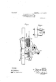
- Fig. 3 is a view in side elevation oi the circuit breaking device shown in Fig. 2,
- Fig. 4 is a plan view of some of the details of the circuit breaking device shown in Figs. 2 and 3.
- the controller 5 comprises the ordinary means for connecting the terminals of an armature winding 10 of a motor 11 to the source of multivoltagc energy and for varying the resistance in the circuit of the field magnet winding 12 that is connected across one 3 iir oi the distributing conductors.
- Contact or- Ininal S of the controller 5 is electrically connected to stationary terminal 13 of a circuit breaker 14, the other stationary terminal 15 of which is connected to one terminal of magnet winding 16 ofa switch 17.
- the other terminal of winding 16 18 connected to terminal 18 of line switch 9.
- the movable contact terminal 19 of the circuit breaker l l is attached to the core 20 oi a solenoid 21, the respective terminals of which are connected to terminal 15 and stationary terminal 22 of the switch 17.
- tionary terminal 22 is also connected to con- Statact linger 23 oi the controller 5.
- the other stationary terminal 24 of the switch 17 is connected to contact lingers U and 2501? controller 5 and to terminal oi line switch 9.
- the switch 17 comprises, besidcs'the operating magnet winding 1e and the stationary terminals 22 and 24, a magnctizable core 27, an armature 28 therefor and a contact terminal 29 which is adapted to engage the stationary terminals 22 and 2 -1- and is raised out oi engagement therewith .when the core 27 is magnetized to such a degree as to raise its armature 28.
- One end 3() ol a lever 31 that is fulcrumed at "2 has a slot and pivot connection with the solenoid core 20 of the circuit breaker 14, and the other end 33 engages the armature 28 in such a manner that the switch 17 is opened when the circuit breaker 14 is opened, but maybe opened independently thereof and may be closed either when the circuit breaker is is closed or independently after it has been closed.
- the coil 21 rai es the core 20 and causes the movable terminal 19 to engage stationary terminals 18 and 15, when the voltage applied to the motor exceeds a predetermined limitingvaluc, and when the end 33 of the lever 31 is lowered, the member 29 of the switch 17 is permitted to engage stationary terminals 22 and 24;
- the core 2-0 is re leased and movable terminal 19 is disengaged from stationary terminals 13 and 15, and movable terminal 29 of the switch 17 is disengaged from terminals 22 and 24 of that circuit breaker.
- the current delivered to the motor exceeds a predetermined limiting value, armature 28 and member 29 are raised and the circuit of the coil 21 is interranted.
- the controller 5 being of the ordinary type which is employed for the purpose ofcontrolling the circuits of electric motors adapted to be supplied with energy from a multivoltage source, it is deemed unnecessary to further describe the circuits in detail. It may be stated, however, that in the first series of po sitions of the controller the armature winding is connected to the low voltage distributing conductors and the strength of the field is gradually reduced. In the succeeding positions of the controller, the armaturev winding is connec ed to the high voltage distributing conductors and the resistance is first included in the circuit of the field magnet winding and is then gradually cut out.
- drum segment 34 engages contact fingers 23 and 25 only when the controller is in its first position. As before explained, if the voltage applied to the motor 11 falls below a predetermined limiting value, the circuit breaker 14 and the switch 17 open and the coil 21 cannot be again energized for the purpose of operating these devices, until the controller is returned to its first position so that drum segment 34 may engage contact fingers 23 and 25. A similar operation becomes necessary if the current supplied to the motor exceeds a predetermined limiting value, since the switch 17 will first open, thereby interrupting the circuit of the coil 21 and allowing the circuit breaker 14 to open. 4
- Terminals 13, 15, 22 and 24, and magnet windin s 16 and 21 may be mounted upon a suitable insulating slab 35, the terminals being provided with any suitable means, such as those shown at-36, for making circuit connections thereto.
- the armature 28 carries at its outer end a bolt 37 having a slotted head 38 through which a pin 39 projects.
- the pin 39 is mounted near the outer end of one arm 40 of a bellcrank lever 42, the other arm 41 of which is provided with a wedgeshaped terminal piece 29 which is adapted to I engage and electrically connect terminals 22 and 24.
- Means for normally maintaining the switch 17 in its closed position comprises a weight 43 that is carried at the outer end of the bellcrank lever arm 40 and is ad justable in position thereon.
- the armature 28 may be adapted to move under the action of different magneto-motive forces, by loading it with a greater or less number ofweights 44.
- a circuit-breaking means comprising a main switch, an actuating coil therefor, an auxiliary switch in thef circuit of said coil, an actuating coil fol-said 8 auxiliary switch that is in circuit with the main switch, and a third switch that is meehanically operated by the circuit controller to close the circuit of the actuating coil of the main switch only when the circuit controller 8 is in its initial position.
- a circuit breaking means comprising a main switch, an actuati ing coil therefor, an auxiliary switch'in the circuit of said coil, an actuating coil for said auxiliary switch that is in circuit with the main switch, and a governing switch for the circuit of the main switch actuating coil, said o governing switch constituting part of the circuit cont-roller and being closed only when said controller is in its initial position.
- the cornbination with a source of electrical energy and a, translating device, of a main (circuit switch, an auxiliary circ it switch and means for causing the t ⁇ o switches to open when the voltage applied to the translating device falls below a predetermined liinitin value.
Landscapes
- Driving Mechanisms And Operating Circuits Of Arc-Extinguishing High-Tension Switches (AREA)
Description
PATENTED JUNE 11, 1907. G. LAIRD & J. P. TODD. ELECTRICAL CONTROLLER.
APPLICATION FILED FEBA, 1905.
- 3 SHEETS-SHEET 1.
WLTNES'SES: zidm AT'TORNEY No. 856,476. PATENTED JUNE 11, 1907v G. LAIRD & J. P. TODD.
ELECTRICAL CONTROLLER.
APPLICATION FILED IEB.4,1905- 3 SHEETS-SHEET 2,
WlTNESSES! VENTURE zoa/azw "mi W ((24, 0. 6% B 2 AT'TORNY PATENTED JUNE 11, 1907. G. LAIRD & J. P. TODD. ELECTRICAL CONTROLLER.
APPLICATION FILED FEB. 4, 1905.
3 $HBETS-SHBET 3 Fig. 3.
Wm 43' 33 37 I lfmwwg 'pma "A.
Wnugssas: q Qu mvgwas ilgi fizan/ M L ATTORNEY GEORGE LAIRD AND JOHN PEROIVAL TODD, OF MANCHESTER, ENGLAND,
'ASSIQNORS TO WESTINGHOUSE ELECTRT & MANUFACTURING COM- PANY, A. CORPORATION OF PENNSYLVANIA.
ELEOTHiQ-AL CONTROLLER.
Specification of Letters Patent.
Xatented June 11, 19021 Application filed February 4:, 1905. Serial No. $14,180.
To all whom it may con/come.-
Be it known that we, Gnonon Lame and JOHN PnRcrvAL Tonn, subjects of the King of Great Britain, and residents of Manchester, in the county of Lancaster, England,
have invented a new and useful improvemay be employed in the system shown in lfig. 1. Fig. 3 is a view in side elevation oi the circuit breaking device shown in Fig. 2,
and Fig. 4 is a plan view of some of the details of the circuit breaking device shown in Figs. 2 and 3.
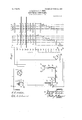
Energy is supplied to distributing conductors 1, 2 and 3 from suitable source of inultivoltage energy, and circuitconnections are made with a controller 5 through its stationary contact terminals 6, 7 and 8, a line switch 9 being provided for the purpose of making and breaking such circuit connections.
The controller 5 comprises the ordinary means for connecting the terminals of an armature winding 10 of a motor 11 to the source of multivoltagc energy and for varying the resistance in the circuit of the field magnet winding 12 that is connected across one 3 iir oi the distributing conductors. Contact or- Ininal S of the controller 5 is electrically connected to stationary terminal 13 of a circuit breaker 14, the other stationary terminal 15 of which is connected to one terminal of magnet winding 16 ofa switch 17. The other terminal of winding 16 18 connected to terminal 18 of line switch 9.
The movable contact terminal 19 of the circuit breaker l l is attached to the core 20 oi a solenoid 21, the respective terminals of which are connected to terminal 15 and stationary terminal 22 of the switch 17. tionary terminal 22 is also connected to con- Statact linger 23 oi the controller 5. The other stationary terminal 24 of the switch 17 is connected to contact lingers U and 2501? controller 5 and to terminal oi line switch 9.
The switch 17 comprises, besidcs'the operating magnet winding 1e and the stationary terminals 22 and 24, a magnctizable core 27, an armature 28 therefor and a contact terminal 29 which is adapted to engage the stationary terminals 22 and 2 -1- and is raised out oi engagement therewith .when the core 27 is magnetized to such a degree as to raise its armature 28.
One end 3() ol a lever 31 that is fulcrumed at "2 has a slot and pivot connection with the solenoid core 20 of the circuit breaker 14, and the other end 33 engages the armature 28 in such a manner that the switch 17 is opened when the circuit breaker 14 is opened, but maybe opened independently thereof and may be closed either when the circuit breaker is is closed or independently after it has been closed.
The coil 21 rai es the core 20 and causes the movable terminal 19 to engage stationary terminals 18 and 15, when the voltage applied to the motor exceeds a predetermined limitingvaluc, and when the end 33 of the lever 31 is lowered, the member 29 of the switch 17 is permitted to engage stationary terminals 22 and 24;
If the voltage applied to the motor falls below a predetermined value, the core 2-0 is re leased and movable terminal 19 is disengaged from stationary terminals 13 and 15, and movable terminal 29 of the switch 17 is disengaged from terminals 22 and 24 of that circuit breaker. ll the current delivered to the motor exceeds a predetermined limiting value, armature 28 and member 29 are raised and the circuit of the coil 21 is interranted.
if the lineswitch 9 is closed and the controller 5 occupies position a, the drum seg ment 3e connects contact fii'igers 2% and and a circuit is thus established from dis tributing conductor 1 through line switch 9, .magnet winding 16 oi switch 17, coil 21 of circuit breaker 14', stationary terminal 22, contact linger 23, drum segment 34, Contact finger 25, stationary terminal 24, line switch 9 and distributing conductor 3. The coil 21,
being thus energized, closes the circuit] breaker 14 and the switch 17 is also released and allowed to close. As soon as the switch 17 is closed, the circuit of the coil 21 is completed through the circuit breaker 14, and then if the controller 5 is moved to its succeeding positions, current will be supplied to the motor 1 l.
The controller 5 being of the ordinary type which is employed for the purpose ofcontrolling the circuits of electric motors adapted to be supplied with energy from a multivoltage source, it is deemed unnecessary to further describe the circuits in detail. It may be stated, however, that in the first series of po sitions of the controller the armature winding is connected to the low voltage distributing conductors and the strength of the field is gradually reduced. In the succeeding positions of the controller, the armaturev winding is connec ed to the high voltage distributing conductors and the resistance is first included in the circuit of the field magnet winding and is then gradually cut out.
It is to be noted that drum segment 34 engages contact fingers 23 and 25 only when the controller is in its first position. As before explained, if the voltage applied to the motor 11 falls below a predetermined limiting value, the circuit breaker 14 and the switch 17 open and the coil 21 cannot be again energized for the purpose of operating these devices, until the controller is returned to its first position so that drum segment 34 may engage contact fingers 23 and 25. A similar operation becomes necessary if the current supplied to the motor exceeds a predetermined limiting value, since the switch 17 will first open, thereby interrupting the circuit of the coil 21 and allowing the circuit breaker 14 to open. 4
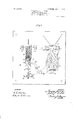
The circuit breaking devices which I have described in the foregoing part of the specification are shown in Figs. 2, 3 and 4. Terminals 13, 15, 22 and 24, and magnet windin s 16 and 21 may be mounted upon a suitable insulating slab 35, the terminals being provided with any suitable means, such as those shown at-36, for making circuit connections thereto. The armature 28 carries at its outer end a bolt 37 having a slotted head 38 through which a pin 39 projects.
The pin 39 is mounted near the outer end of one arm 40 of a bellcrank lever 42, the other arm 41 of which is provided with a wedgeshaped terminal piece 29 which is adapted to I engage and electrically connect terminals 22 and 24. Means for normally maintaining the switch 17 in its closed position comprises a weight 43 that is carried at the outer end of the bellcrank lever arm 40 and is ad justable in position thereon. The armature 28 may be adapted to move under the action of different magneto-motive forces, by loading it with a greater or less number ofweights 44.
The mechanical details of the apparatus which may be employed for securing the results that we have hereinbefore set forth may be largely varied within the scope of our invention, and we therefore desire to 7 cover and include all variations that do not impart material changes in operation or result.
To claim as our invention:
1. The combination with a source of elec- 7 tricalenergy, a translating device and a cir cuit controller therefor, of a circuit-breaking means comprising a main switch, an actuating coil therefor, an auxiliary switch in thef circuit of said coil, an actuating coil fol-said 8 auxiliary switch that is in circuit with the main switch, and a third switch that is meehanically operated by the circuit controller to close the circuit of the actuating coil of the main switch only when the circuit controller 8 is in its initial position.
2. The combmation with a source of electrical ener y, a translating device and a circuit contro ler therefor, of a circuit breaking means comprising a main switch, an actuati ing coil therefor, an auxiliary switch'in the circuit of said coil, an actuating coil for said auxiliary switch that is in circuit with the main switch, and a governing switch for the circuit of the main switch actuating coil, said o governing switch constituting part of the circuit cont-roller and being closed only when said controller is in its initial position.
3. The combination with a source of elec trical ener a translating device and a eir 1c cuit contrriller therefor, of a circuit breaking device comprising a main circuit switch, an operating coil therefor, an auxiliary switch in the circuit thereof, an operatingcoil therefor which is in circuit with the main switch, 1c
means connecting the two switches that causes the auxiliary switch to open when the main switch is opened and which also permits the auxiliary switch to open independently of the main switch, and a manually oper- II ated switch in the circuit of the operating coil of the main switch.
4. The combination with a source of electrical energy and a translating device, of a main switch that is normally closed and is 11 opened when the voltage applied to the transrating device falls below a predetermined limiting value, and an auxiliary switch which is interlocked with the main switch to be opened thereby and is independently opened I2 when the current traversing the circuit exceeds a predetermined limitingvalue.
5. The combination'with a source of electrical energy and a translating device, of a main switch that is normally closed and is 12 opened when the voltage applied to the translating device falls below a predetermined limiting value, an auxiliary switch which is interlocked with the main switch to be openedthereby and is independently opened 13c 1 when the current traversing the circuit ex- .ceeds a predetermined limiting value, and a manually-o erated switch which controls the operation 0 the main switch.
- 6. The cornbinationwith a source of electrical energy and a, translating device, of a main (circuit switch, an auxiliary circ it switch and means for causing the t\ o switches to open when the voltage applied to the translating device falls below a predetermined liinitin value.
7. The com ination with a source of electrical energy and a'translating device, of" a main switch having an actuating coil, an auxiliary switch, a coil and mechanism under the influence thereof for openm the auxiliary switch when the current in t 1e main cir-- cult exceeds a predetermined hmltmg value,
and mechanism between the two switches that opens the auxiliary switch when the main switch opens and permits the former to open independently of the latter.
8. The combination with a source of elec-- trical energy, a translating device and a circuit controller therefor, of an electro-mag netically-actuated switch that is normally closed and is opened when the voltage applied. to the translating device falls -lwlow a predetermined limiting value, an auxiliary switch that is mechanically interlocked with the main switch to be actuated thereby but is independently opened when the currenttraversing the main circuit exceeds a predetermined limiting value, and-a third switch that is operated by the controller and serves. to efi'ect closure of the main switch only when the controller occupies its first position.
9. The combination with a sourceof elec- I trical ener y, a translating device and a circuit contro ler therefor, of a main switch that is normally closed and is opened when the voltage applied to the translating device falls below a predetermined limiting value, an auxiliary switch that is o sued by the opening of the main switch and is independently opened when the current traversing the main'circuit exceeds a predetermined limiting value, and a switch that is opened and closed by the controller to control the operation of the main switch.
10. The combination with a source of electrical energy, a translating deviceand a circuit controller therefor, of a main circuit switch that is normally closed and is o ened when the voltage applied to the trans ating device falls below a predetermined limiting value, an auxiliary switch which is normally closed and is opened when the current traversing the main circuit exceeds a predetermined limiting value, and means for preventing closure of the said switches except
Priority Applications (1)
| Application Number | Priority Date | Filing Date | Title |
|---|---|---|---|
| US1905244180 US856476A (en) | 1905-02-04 | 1905-02-04 | Electrical controller. |
Applications Claiming Priority (1)
| Application Number | Priority Date | Filing Date | Title |
|---|---|---|---|
| US1905244180 US856476A (en) | 1905-02-04 | 1905-02-04 | Electrical controller. |
Publications (1)
| Publication Number | Publication Date |
|---|---|
| US856476A true US856476A (en) | 1907-06-11 |
Family
ID=2924931
Family Applications (1)
| Application Number | Title | Priority Date | Filing Date |
|---|---|---|---|
| US1905244180 Expired - Lifetime US856476A (en) | 1905-02-04 | 1905-02-04 | Electrical controller. |
Country Status (1)
| Country | Link |
|---|---|
| US (1) | US856476A (en) |
Cited By (1)
| Publication number | Priority date | Publication date | Assignee | Title |
|---|---|---|---|---|
| US2549304A (en) * | 1946-05-07 | 1951-04-17 | Westinghouse Electric Corp | Control system |
-
1905
- 1905-02-04 US US1905244180 patent/US856476A/en not_active Expired - Lifetime
Cited By (1)
| Publication number | Priority date | Publication date | Assignee | Title |
|---|---|---|---|---|
| US2549304A (en) * | 1946-05-07 | 1951-04-17 | Westinghouse Electric Corp | Control system |
Similar Documents
| Publication | Publication Date | Title |
|---|---|---|
| US856476A (en) | Electrical controller. | |
| US1125077A (en) | Circuit-breaker. | |
| US790983A (en) | Switch for electric circuits. | |
| US1017060A (en) | System of electric-current distribution. | |
| US786017A (en) | Starting-rheostat. | |
| US882687A (en) | Electrical control system. | |
| US601871A (en) | Electromagnetic circuit-breaker | |
| US664080A (en) | Motor-switch. | |
| US820877A (en) | Controller for electric circuits. | |
| US953021A (en) | Electric switch. | |
| US1231599A (en) | Motor-control system. | |
| US911592A (en) | Multiple switch-starter. | |
| US1554318A (en) | System for controlling electric motors | |
| US890621A (en) | Circuit-controlling device. | |
| US897497A (en) | Starting and speed-regulating rheostat. | |
| US1018547A (en) | Circuit-breaker. | |
| US1269625A (en) | Auto-starter. | |
| US914356A (en) | Electric-circuit controller. | |
| US730342A (en) | System of motor control. | |
| US991556A (en) | High and low potential selective switch system. | |
| US774764A (en) | System of electrical distribution. | |
| US793494A (en) | Controller. | |
| US1665858A (en) | Circuit interrupter | |
| US892421A (en) | System of electric-motor control. | |
| US1448381A (en) | Control system |