US856473A - Drilling-machine. - Google Patents
Drilling-machine. Download PDFInfo
- Publication number
- US856473A US856473A US31785106A US1906317851A US856473A US 856473 A US856473 A US 856473A US 31785106 A US31785106 A US 31785106A US 1906317851 A US1906317851 A US 1906317851A US 856473 A US856473 A US 856473A
- Authority
- US
- United States
- Prior art keywords
- drill
- frame
- nut
- shaft
- drilling
- Prior art date
- Legal status (The legal status is an assumption and is not a legal conclusion. Google has not performed a legal analysis and makes no representation as to the accuracy of the status listed.)
- Expired - Lifetime
Links
Images

Classifications
-
- B—PERFORMING OPERATIONS; TRANSPORTING
- B23—MACHINE TOOLS; METAL-WORKING NOT OTHERWISE PROVIDED FOR
- B23B—TURNING; BORING
- B23B5/00—Turning-machines or devices specially adapted for particular work; Accessories specially adapted therefor
- B23B5/16—Turning-machines or devices specially adapted for particular work; Accessories specially adapted therefor for bevelling, chamfering, or deburring the ends of bars or tubes
-
- F—MECHANICAL ENGINEERING; LIGHTING; HEATING; WEAPONS; BLASTING
- F16—ENGINEERING ELEMENTS AND UNITS; GENERAL MEASURES FOR PRODUCING AND MAINTAINING EFFECTIVE FUNCTIONING OF MACHINES OR INSTALLATIONS; THERMAL INSULATION IN GENERAL
- F16L—PIPES; JOINTS OR FITTINGS FOR PIPES; SUPPORTS FOR PIPES, CABLES OR PROTECTIVE TUBING; MEANS FOR THERMAL INSULATION IN GENERAL
- F16L41/00—Branching pipes; Joining pipes to walls
- F16L41/04—Tapping pipe walls, i.e. making connections through the walls of pipes while they are carrying fluids; Fittings therefor
- F16L41/06—Tapping pipe walls, i.e. making connections through the walls of pipes while they are carrying fluids; Fittings therefor making use of attaching means embracing the pipe
-
- Y—GENERAL TAGGING OF NEW TECHNOLOGICAL DEVELOPMENTS; GENERAL TAGGING OF CROSS-SECTIONAL TECHNOLOGIES SPANNING OVER SEVERAL SECTIONS OF THE IPC; TECHNICAL SUBJECTS COVERED BY FORMER USPC CROSS-REFERENCE ART COLLECTIONS [XRACs] AND DIGESTS
- Y10—TECHNICAL SUBJECTS COVERED BY FORMER USPC
- Y10T—TECHNICAL SUBJECTS COVERED BY FORMER US CLASSIFICATION
- Y10T408/00—Cutting by use of rotating axially moving tool
- Y10T408/55—Cutting by use of rotating axially moving tool with work-engaging structure other than Tool or tool-support
- Y10T408/561—Having tool-opposing, work-engaging surface
- Y10T408/5617—Laterally adjustable surface
-
- Y—GENERAL TAGGING OF NEW TECHNOLOGICAL DEVELOPMENTS; GENERAL TAGGING OF CROSS-SECTIONAL TECHNOLOGIES SPANNING OVER SEVERAL SECTIONS OF THE IPC; TECHNICAL SUBJECTS COVERED BY FORMER USPC CROSS-REFERENCE ART COLLECTIONS [XRACs] AND DIGESTS
- Y10—TECHNICAL SUBJECTS COVERED BY FORMER USPC
- Y10T—TECHNICAL SUBJECTS COVERED BY FORMER US CLASSIFICATION
- Y10T408/00—Cutting by use of rotating axially moving tool
- Y10T408/55—Cutting by use of rotating axially moving tool with work-engaging structure other than Tool or tool-support
- Y10T408/561—Having tool-opposing, work-engaging surface
- Y10T408/5626—Having tool-opposing, work-engaging surface with means to move Tool relative to other work-engaging structure along tool-axis
- Y10T408/5627—Having sliding engagement therewith
- Y10T408/56275—Screw coaxial with Tool
-
- Y—GENERAL TAGGING OF NEW TECHNOLOGICAL DEVELOPMENTS; GENERAL TAGGING OF CROSS-SECTIONAL TECHNOLOGIES SPANNING OVER SEVERAL SECTIONS OF THE IPC; TECHNICAL SUBJECTS COVERED BY FORMER USPC CROSS-REFERENCE ART COLLECTIONS [XRACs] AND DIGESTS
- Y10—TECHNICAL SUBJECTS COVERED BY FORMER USPC
- Y10T—TECHNICAL SUBJECTS COVERED BY FORMER US CLASSIFICATION
- Y10T408/00—Cutting by use of rotating axially moving tool
- Y10T408/65—Means to drive tool
- Y10T408/675—Means to drive tool including means to move Tool along tool-axis
- Y10T408/6771—Means to drive tool including means to move Tool along tool-axis with clutch means
- Y10T408/6774—Means to drive tool including means to move Tool along tool-axis with clutch means including plural speed drive
Definitions
- My invention relates to improvements in drilling machines for hand drilling, and is particularly applicable for drilling rail road rails when laid in a track, but by means of slight changes, more particularly in its frame, can be used for almost any kind of hand drilling, such changes as may be required for adapting the machine for other uses than rail drilling, I consider as within the scope of my invention.
- the improvements consist in the manner of constructing the frame of the machine, in the construction of its clutching mechanism, for operating its drill, in a foot controlled feeding mechanism, a rapid drill advancing and receding mechanism, and a feed screw having uncommonly coarse threads for the rapid receding of the drill from a rail whenever the quick detachment of the machine from a rail is required by reason of the sudden approach of a train, said improvements being shown in the accompanying drawing, in which,-
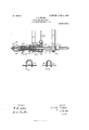
- Figure 1 is a top view of the drilling machine, a part of its frame being broken away at its right hand end and a part of the ends of its supporting plank at the left hand end be-
- Fig. 2 is a vertical section of the machine on the line a, a, of Fig. 1.
- Fig. 3 is a side elevation of the machine, its frame near the right hand end being broken for want of room on the sheet for the full length of the frame, and along the entire length of its front for the better showing of its working mechanism.
- Fig. 4 is a vertical section of the clutch operating device, this being the left hand clutch, but in a different position from that shown in Figs. 1, 2 and 3.
- Fig. 5 is aside elevation of the clutch and a short section of its shaft.
- Fig. 6 is atransverse section of the feed screw shaft, its nut, and a side view of a part of its brake band, as seen in looking to the left of line b, b, of Fig. 1.
- Fig. 7 is a side elevation upon a reduced scale, of the machine frame.
- Fig. 8 is a longitudinal view along the line of the drill shaft, the right hand end being in elevation and the left hand end in section, the latter showing the drill shaft, its journal boxes, its thrust Similar numerals and characters indicate.
- the transverse sills of the angular frames for supporting the upper works of the machine, they having uprights 4 and top rail 4;.
- These uprights are provided near their lower ends with crimps, or short bends 5, which rest on the upper edges of side sills 1, and their extreme lower ends are provided with bonds 6 which are bent under the lower edges of said sills so that they are held firmly between the bends 5 and 6, and a bolt 7 being inserted through said frames and sills, the frame is adapted to withstand any strain longitudinally of the frame which the operation of its upper works may impose.
- Another reason for the bends 5 in the angular frames is, to prevent the hooks 2 from working upward upon the rail during the operation of drilling.
- brackets S Near the left hand or rear end of the frame are two brackets S, which are secured to the frame with bolts 9 and to these brackets are attached with bolts 10, a plank 11 for providing a firm support for the frame on the road bed while drilling.
- a drill shaft 12 Arixngedlengthwise of the frame is a drill shaft 12, having a drill socket 13 in one end, and threads 12, from its rear end to near its mid-length, and having a round nut 14, engaging said threads and extending from the right hand end of said threads to about one inch beyond the endof said shaft, the nut having an extension with a hardened point 16 which is arranged to revolve against the thrust bolt head. 17, the bolt being inserted through the end sill of the frame and having a jam nut 18 on the dog.
- each side of the sill for its adjustment endwise.
- the nut 14 is mounted for revolution, the shaft 12 revolving in said nut and in the box 19, on the forward cross sill.
- These boxes may be secured to the sills in any convenient manner, in the present case, it is with bands 20, having nuts 21. WVhen the drill socket is bac k against the journal box 19 of the forward cross sill, the threaded part of the drill shaft is to extend to just through the box 1.5.
- the clutches are similar in construction and operation, but their bands being arranged upon the collars in a different posi tion circumferentially, and being connected to the operating levers by different lengths of connections, the oscillation of its operating lever in one direction will operate to turn its clutch in the direction of the arrow, while its oscillation in the opposite direction will act on the other clutch and turn it in the same direction, thus making the oscillation of its operating lever back and forth roduce a continuous rotary motion in one irection, and without any lost motion.
- the mechanism for its operation consists of the following: Mounted upon the top of the angular frames is a nonrotating shaft 29, it being held in position upon said frames by means of bands 30, the ends of which pass through the rails 4, and are provided with nuts.
- a collar 31 having an arm 32 extending upward for the attachment of lever handle 33, and arms 34 and 35 extend ing downward upon opposite sides of the collar for their connection by means of links 36 and 37 with levers 38 and 39, which are connected with clutch bands 24.
- the several downward extending arms, links, levers and clutch bands are hinged together by means of pins 40.
- a pinion 41 is secured to or made integral with the nut 14, for its quick withdrawal.
- the shaft 29 is bent downward and a gear wheel 42, mounted for revolution upon the extending end 43, the wheel having its teeth in mesh with those of the pinion 41, said wheel being retained in position upon the end 43 by means of a pin 44, and being provided with a handle 45.
- t e drill can be set up to the work or withdrawn from it.
- the journal box 15 is extended to the pinion, so that the nut 14 is prevented from endwise movement by being confined between the box 15 and bolt head 17, the pointed end 16, being a continuation of the nut 14.
- the feed of the drill is made of any desired rate by mounting a band of thin steel or other suitable material, 46, upon the nut 14, one end being attached to the frame by bolt 47 and the other, carried around the nut and formed into a suitable form of lever for being pressed downward by the foot of the operator.
- a cross bar 50 is secured in a suitable manner, as by projecting its ends through the sills and heading them down.
- cross bar is provided with a screw 51, which is arranged in a direct line with the axis of the drill shaft, by the turning of which, the forward end of the frame can be raised or lowered for bringing the point of the drill in the right position for drilling the rail.
- the o erator is to stand in front of the gear wheei: with one foot on the brake lever, and with his right hand oscillate the handle 33, back and forth, the left hand being free for turning the wheel 42 as occasion requires.
- the nut if left free will revolve with the screw and no feed will be produced, but upon the operators pressing downward upon the foot lever, more or less, the revolution of the nut can be retarded, and the feed thereby adapted to the requirements demanded by the size of the drill, the hardness of material, &c.
- the wheel-42 is to be turned and the drill withdrawn, when it can be adjusted in position for another The hole or the machine removed from the rail as occasion requires.
- the gear wheel may be used as a hand feed in using a small drill, as by turning the wheel forward, the feed can be governed as required.
- a frame for a drilling machine formed of three pieces of bar steel, com rising first, two longitudinal side sills place on edge, a rear transverse sill, and a hook adapted to be hooked over a rail road rail at the forward end of each side sill, all in one piece, second, two similar continuous bands, bent flatwise, forming each a cross sill, two uprights and a top rail, the two uprights of each band having a crimp, or bend, near their cross sills-adapted to receive between said crimps and the cross sills, the side sills of said first named piece, and suitable bolts through said uprights and side sills at the four connecting points thereof, substantially as described.
- a frame therefor a drill shaft arranged lengthwise of said frame, a bearing upon said frame for supporting the forward end of said shaft and in which it revolves, a second hearing arranged on said frame between the first named bearing and the rear end of said shaft, in which the shaft is supported, a screw thread upon said shaft extending from near its mid-length to its rear end, a nut mounted upon said threads, its forward end being round and revoluble in said second bearing and the rear one round for the action of a feed controlling means thereon, it extending beyond the rear end of said threads, a thrust bearing arranged to bear against said rear end, a pinion upon and revoluble with said nut intermediate its ends and arranged to hold said nut from endwise movement be tween said second named and the thrust.
- a drill shaft arranged lengthwise of said frame, a bearing upon said frame for supporting the forward end of said shaft and in which it revolves, a second bearing arranged on said frame between the first named bearing and the rear end of said shaft, in which the shaft is supported, a screw thread upon said. shaft, extending .from near its mid-length to its rear end, a nut mounted upon said threads, its forward end being round and revoluble in said second bearing, and the rear one round for receiving a feed controlling brake band and.
- a thrust bearing arranged to bear against said rear end, a pinion upon and revoluble with said nut, between said round ends and adapted to hold said nut between said second named and thrust bearings aforesaid from endwise movement, mechanism engaging said pinion for setting the drill up to and for its quick withdrawal from the work in hand, and a brake band partially encircling a portion of the rear end of said nut and being arranged in a suitable position for being pressed downward by the foot of the operator for governing the rate of feed of the drill shaft, substantially as set forth.
- a drill holding shaft mounted for revolution upon a suitable frame, and having mechanism for revolving said shaft, a screw thread formed upon the rear portion of said shaft, a nut, round upon the outside of each end, mounted upon said threads, a bearing arranged upon the frame in which the forward end of said nut is arranged for revolution, a thrust bearing arranged at the rear end of the frame with which the rear end of said nut engages, and a brake for governing the rate of feed of the drill shaft comprising a band of spring metal partially encircling a portion of the rear end of said nut, one end of the band being socured in a fixed position, and the other free end being arranged in position for being pressed downward by the foot of the opera tor, and thereby clasping the band around a portion of the circinnference of said nut.
Description
PATENTED JUNE 11, 1 907.
1). E, KRAUSE. DRILLING MACHINE.
APPLICATION FILED HAY 21,1906.
2 SHEETS BHEE'I' 1.
mmvrok Ilaqie] HKYausn- ATTORNEY E N RRI: PETERS co., WASHINGTON, o. c.
No. 856,473; PATENTBD JUNE 11 1907. 1). E. KRAUSE. DRILLING MACHINE. APPLIGATIOH FILED MAY 21, 1906.
- 2 SHEETS-SHEET 2.
17" 2,0 2 q.) I 157 '16 14 was 19 .46 11 Tiga 413 12 M 1 3 211 Ti i 13 110 WITNESSES: "WE/WIN :Ua 191E BEJISE 4f. I] By K ATTORNEY rnx "onus PEYERS cm, WASNINGYON. n. c.
ing broken off.
UNITED STATES PATENT OFFICE.
DRILLING-MACHINE.
Specification of Letters Patent.
Patented June 11, 1907.
Application filed May 21,1906. Serial No. 317.851.
To all whom it may concern-.-
Be it known that I, DANIEL E. KRAUsn, a citizen of the United States, residing at Chase, in the county of Oconto and State of WVisconsin, have invented a new and useful Improvement in Drilling-Machines, of which the following is a specification.
My invention relates to improvements in drilling machines for hand drilling, and is particularly applicable for drilling rail road rails when laid in a track, but by means of slight changes, more particularly in its frame, can be used for almost any kind of hand drilling, such changes as may be required for adapting the machine for other uses than rail drilling, I consider as within the scope of my invention.
The improvements consist in the manner of constructing the frame of the machine, in the construction of its clutching mechanism, for operating its drill, in a foot controlled feeding mechanism, a rapid drill advancing and receding mechanism, and a feed screw having uncommonly coarse threads for the rapid receding of the drill from a rail whenever the quick detachment of the machine from a rail is required by reason of the sudden approach of a train, said improvements being shown in the accompanying drawing, in which,-
Figure 1 is a top view of the drilling machine, a part of its frame being broken away at its right hand end and a part of the ends of its supporting plank at the left hand end be- Fig. 2 is a vertical section of the machine on the line a, a, of Fig. 1. Fig. 3 is a side elevation of the machine, its frame near the right hand end being broken for want of room on the sheet for the full length of the frame, and along the entire length of its front for the better showing of its working mechanism. Fig. 4 is a vertical section of the clutch operating device, this being the left hand clutch, but in a different position from that shown in Figs. 1, 2 and 3. Fig. 5 is aside elevation of the clutch and a short section of its shaft. Fig. 6 is atransverse section of the feed screw shaft, its nut, and a side view of a part of its brake band, as seen in looking to the left of line b, b, of Fig. 1. Fig. 7 is a side elevation upon a reduced scale, of the machine frame. Fig. 8 is a longitudinal view along the line of the drill shaft, the right hand end being in elevation and the left hand end in section, the latter showing the drill shaft, its journal boxes, its thrust Similar numerals and characters indicate.
like parts in all of the views.
1, indicates the sills of the frame of the machine, which frame for the sake of having the greatest strength with the least weight of material, is preferably made of flat bar steel of a suitable size, placed on edge and bent at the rear end for forming the rear end sill, and at its front end for forming the hooks 2, for hooking the frame over a rail.
3, 3, are the transverse sills of the angular frames for supporting the upper works of the machine, they having uprights 4 and top rail 4;. These uprights are provided near their lower ends with crimps, or short bends 5, which rest on the upper edges of side sills 1, and their extreme lower ends are provided with bonds 6 which are bent under the lower edges of said sills so that they are held firmly between the bends 5 and 6, and a bolt 7 being inserted through said frames and sills, the frame is adapted to withstand any strain longitudinally of the frame which the operation of its upper works may impose. Another reason for the bends 5 in the angular frames is, to prevent the hooks 2 from working upward upon the rail during the operation of drilling.
Near the left hand or rear end of the frame are two brackets S, which are secured to the frame with bolts 9 and to these brackets are attached with bolts 10, a plank 11 for providing a firm support for the frame on the road bed while drilling. Arixngedlengthwise of the frame is a drill shaft 12, having a drill socket 13 in one end, and threads 12, from its rear end to near its mid-length, and having a round nut 14, engaging said threads and extending from the right hand end of said threads to about one inch beyond the endof said shaft, the nut having an extension with a hardened point 16 which is arranged to revolve against the thrust bolt head. 17, the bolt being inserted through the end sill of the frame and having a jam nut 18 on the dog.
each side of the sill for its adjustment endwise. In the journal box 15, the nut 14 is mounted for revolution, the shaft 12 revolving in said nut and in the box 19, on the forward cross sill. These boxes may be secured to the sills in any convenient manner, in the present case, it is with bands 20, having nuts 21. WVhen the drill socket is bac k against the journal box 19 of the forward cross sill, the threaded part of the drill shaft is to extend to just through the box 1.5. At this point are firmly secured two similar clutch collars, 22 and 23, each one being turned off round and provided with a band of spring steel, 24, (one collar wide enough for both bands would be just as good,) and with a dog, 25, formed of suitable material, it having one leg sharpened to a point for engaging the outer surface of the clutch collar, said dog being held in position within the band by means ofa set screw, 27, which passes through the band and has its end pointed and entered slightly into the outer surface of the curve of These bands are preferably made of two thin leaves of spring metal, and when so made the two ends of the leaves maybe connected together at any convenient point, in the present case it being by means of the set screw 27, which passes through their lap ed ends and engages the dog. The two col ars being arranged side by side, it is only necessary to provide a flange 28 upon but one end of each collar for the retention of the bands 24. These bands after being formed are connected at their ends to levers which are arranged to be operated in such a manner as to tighten and loosen alternately, said bands, during the oscillating motion of their operaing handles, and in doing so to cause the sharp pointed leg of the dog to engage the outer surface of the collar to which it be longs and turn said collar and consequently, turn the drill shaft.
The clutches are similar in construction and operation, but their bands being arranged upon the collars in a different posi tion circumferentially, and being connected to the operating levers by different lengths of connections, the oscillation of its operating lever in one direction will operate to turn its clutch in the direction of the arrow, while its oscillation in the opposite direction will act on the other clutch and turn it in the same direction, thus making the oscillation of its operating lever back and forth roduce a continuous rotary motion in one irection, and without any lost motion. The mechanism for its operation consists of the following: Mounted upon the top of the angular frames is a nonrotating shaft 29, it being held in position upon said frames by means of bands 30, the ends of which pass through the rails 4, and are provided with nuts. Loosely mounted upon said shaft is a collar 31, having an arm 32 extending upward for the attachment of lever handle 33, and arms 34 and 35 extend ing downward upon opposite sides of the collar for their connection by means of links 36 and 37 with levers 38 and 39, which are connected with clutch bands 24. The several downward extending arms, links, levers and clutch bands are hinged together by means of pins 40.
For setting the drill up to the piece to be drilled, and also, for its quick withdrawal, a pinion 41, is secured to or made integral with the nut 14,.the shaft 29 is bent downward and a gear wheel 42, mounted for revolution upon the extending end 43, the wheel having its teeth in mesh with those of the pinion 41, said wheel being retained in position upon the end 43 by means of a pin 44, and being provided with a handle 45. Upon the operators graspling this handle and turning the wheel, t e drill can be set up to the work or withdrawn from it. It should be noted that the journal box 15 is extended to the pinion, so that the nut 14 is prevented from endwise movement by being confined between the box 15 and bolt head 17, the pointed end 16, being a continuation of the nut 14.
The feed of the drill is made of any desired rate by mounting a band of thin steel or other suitable material, 46, upon the nut 14, one end being attached to the frame by bolt 47 and the other, carried around the nut and formed into a suitable form of lever for being pressed downward by the foot of the operator.
In applying the drill for dr1ll1ng rails, as 49, a cross bar 50, is secured in a suitable manner, as by projecting its ends through the sills and heading them down. cross bar is provided with a screw 51, which is arranged in a direct line with the axis of the drill shaft, by the turning of which, the forward end of the frame can be raised or lowered for bringing the point of the drill in the right position for drilling the rail. In operating the drill after it is applied to a rail as shown in Fig. 3, the o erator is to stand in front of the gear wheei: with one foot on the brake lever, and with his right hand oscillate the handle 33, back and forth, the left hand being free for turning the wheel 42 as occasion requires. In turning the drill shaft by means of the oscillation of the handle 33, and of the action of the arms 34 and 35 upon the clutches, the nut if left free will revolve with the screw and no feed will be produced, but upon the operators pressing downward upon the foot lever, more or less, the revolution of the nut can be retarded, and the feed thereby adapted to the requirements demanded by the size of the drill, the hardness of material, &c. Upon the completion of one hole, the wheel-42 is to be turned and the drill withdrawn, when it can be adjusted in position for another The hole or the machine removed from the rail as occasion requires.
I provide the drill shaft with treads out only three to the inch in preference to more, for the purpose of the quick withdrawal of the drill from a rail upon the sudden aproach of a train of cars. This has been found on trial to be better than a larger number, as much time is saved in its operation. The gear wheel may be used as a hand feed in using a small drill, as by turning the wheel forward, the feed can be governed as required.
Having described my invention, what I claim and desire to secure by Letters Patent, is,
1. A frame for a drilling machine formed of three pieces of bar steel, com rising first, two longitudinal side sills place on edge, a rear transverse sill, and a hook adapted to be hooked over a rail road rail at the forward end of each side sill, all in one piece, second, two similar continuous bands, bent flatwise, forming each a cross sill, two uprights and a top rail, the two uprights of each band having a crimp, or bend, near their cross sills-adapted to receive between said crimps and the cross sills, the side sills of said first named piece, and suitable bolts through said uprights and side sills at the four connecting points thereof, substantially as described.
2. In a rail drilling machine, the combination of a frame therefor, a drill shaft arranged lengthwise of said frame, a bearing upon said frame for supporting the forward end of said shaft and in which it revolves, a second hearing arranged on said frame between the first named bearing and the rear end of said shaft, in which the shaft is supported, a screw thread upon said shaft extending from near its mid-length to its rear end, a nut mounted upon said threads, its forward end being round and revoluble in said second bearing and the rear one round for the action of a feed controlling means thereon, it extending beyond the rear end of said threads, a thrust bearing arranged to bear against said rear end, a pinion upon and revoluble with said nut intermediate its ends and arranged to hold said nut from endwise movement be tween said second named and the thrust. bearing aforesaid, a brake band mounted for action upon the rear end of said .nut for controlling the feed of the drill, and a gear wheel mounted for revolution above said pinion and in mesh therewith for setting the drill up to and its quick withdrawal from the work in hand, substantially as described.
3. In a rail drilling machine, the combina tion of a frame therefor, a drill shaft arranged lengthwise of said frame, a bearing upon said frame for supporting the forward end of said shaft and in which it revolves, a second bearing arranged on said frame between the first named bearing and the rear end of said shaft, in which the shaft is supported, a screw thread upon said. shaft, extending .from near its mid-length to its rear end, a nut mounted upon said threads, its forward end being round and revoluble in said second bearing, and the rear one round for receiving a feed controlling brake band and. extending beyond the rear end of said threads, a thrust bearing arranged to bear against said rear end, a pinion upon and revoluble with said nut, between said round ends and adapted to hold said nut between said second named and thrust bearings aforesaid from endwise movement, mechanism engaging said pinion for setting the drill up to and for its quick withdrawal from the work in hand, and a brake band partially encircling a portion of the rear end of said nut and being arranged in a suitable position for being pressed downward by the foot of the operator for governing the rate of feed of the drill shaft, substantially as set forth.
4. In a drilling machine, a drill holding shaft mounted for revolution upon a suitable frame, and having mechanism for revolving said shaft, a screw thread formed upon the rear portion of said shaft, a nut, round upon the outside of each end, mounted upon said threads, a bearing arranged upon the frame in which the forward end of said nut is arranged for revolution, a thrust bearing arranged at the rear end of the frame with which the rear end of said nut engages, and a brake for governing the rate of feed of the drill shaft comprising a band of spring metal partially encircling a portion of the rear end of said nut, one end of the band being socured in a fixed position, and the other free end being arranged in position for being pressed downward by the foot of the opera tor, and thereby clasping the band around a portion of the circinnference of said nut.
D. E. KRAUSE.
Witnesses:
E. J. FOLEY, S. E. FATEK.
Priority Applications (1)
| Application Number | Priority Date | Filing Date | Title |
|---|---|---|---|
| US31785106A US856473A (en) | 1906-05-21 | 1906-05-21 | Drilling-machine. |
Applications Claiming Priority (1)
| Application Number | Priority Date | Filing Date | Title |
|---|---|---|---|
| US31785106A US856473A (en) | 1906-05-21 | 1906-05-21 | Drilling-machine. |
Publications (1)
| Publication Number | Publication Date |
|---|---|
| US856473A true US856473A (en) | 1907-06-11 |
Family
ID=2924928
Family Applications (1)
| Application Number | Title | Priority Date | Filing Date |
|---|---|---|---|
| US31785106A Expired - Lifetime US856473A (en) | 1906-05-21 | 1906-05-21 | Drilling-machine. |
Country Status (1)
| Country | Link |
|---|---|
| US (1) | US856473A (en) |
Cited By (1)
| Publication number | Priority date | Publication date | Assignee | Title |
|---|---|---|---|---|
| US20070015807A1 (en) * | 2005-06-20 | 2007-01-18 | Schering Corporation | Heteroatom-linked substituted piperidines and derivatives thereof useful as histamine H3 antagonists |
-
1906
- 1906-05-21 US US31785106A patent/US856473A/en not_active Expired - Lifetime
Cited By (1)
| Publication number | Priority date | Publication date | Assignee | Title |
|---|---|---|---|---|
| US20070015807A1 (en) * | 2005-06-20 | 2007-01-18 | Schering Corporation | Heteroatom-linked substituted piperidines and derivatives thereof useful as histamine H3 antagonists |
Similar Documents
| Publication | Publication Date | Title |
|---|---|---|
| US856473A (en) | Drilling-machine. | |
| US513088A (en) | Boring-machine | |
| US1085946A (en) | Automatic tube-cutting machine. | |
| US885943A (en) | Rail-drilling machine. | |
| US160536A (en) | Improvement in machines for patching railway-rails | |
| US957199A (en) | Machine for bending tubes. | |
| US448928A (en) | Stone-channeler | |
| US2125371A (en) | Shingle mill | |
| US282687A (en) | threlfall | |
| US651768A (en) | Machine for undermining coal. | |
| US441756A (en) | Drilling-machine | |
| US357255A (en) | Oliver | |
| US1073055A (en) | Gearing. | |
| US259607A (en) | trombly | |
| US614253A (en) | Track-drill | |
| US135613A (en) | Improvement in drilling-machines | |
| US829844A (en) | Hand boring-machine. | |
| US430844A (en) | Ihij petehs co | |
| US51271A (en) | Improvement in stone-cutting machinery | |
| US344892A (en) | Ohaeles o | |
| US153279A (en) | Improvement in mechanisms for operating punches, shears | |
| US1043462A (en) | Nut-tapping machine. | |
| US117017A (en) | Improvement in machines for rolling logs | |
| US176384A (en) | Improvement in nail-plate feeders | |
| US139264A (en) | Improvement in saw-mill head-blocks |