US856467A - Block-signal system. - Google Patents
Block-signal system. Download PDFInfo
- Publication number
- US856467A US856467A US35160507A US1907351605A US856467A US 856467 A US856467 A US 856467A US 35160507 A US35160507 A US 35160507A US 1907351605 A US1907351605 A US 1907351605A US 856467 A US856467 A US 856467A
- Authority
- US
- United States
- Prior art keywords
- track
- block
- signal
- circuit
- current
- Prior art date
- Legal status (The legal status is an assumption and is not a legal conclusion. Google has not performed a legal analysis and makes no representation as to the accuracy of the status listed.)
- Expired - Lifetime
Links
- 238000004804 winding Methods 0.000 description 24
- 230000001939 inductive effect Effects 0.000 description 9
- 230000005540 biological transmission Effects 0.000 description 2
- 201000002531 Karyomegalic interstitial nephritis Diseases 0.000 description 1
- GPUADMRJQVPIAS-QCVDVZFFSA-M cerivastatin sodium Chemical compound [Na+].COCC1=C(C(C)C)N=C(C(C)C)C(\C=C\[C@@H](O)C[C@@H](O)CC([O-])=O)=C1C1=CC=C(F)C=C1 GPUADMRJQVPIAS-QCVDVZFFSA-M 0.000 description 1
- FOIPWTMKYXWFGC-UHFFFAOYSA-N creatinolfosfate Chemical compound NC(=N)N(C)CCOP(O)(O)=O FOIPWTMKYXWFGC-UHFFFAOYSA-N 0.000 description 1
- 230000000694 effects Effects 0.000 description 1
- 230000006698 induction Effects 0.000 description 1
Images
Classifications
-
- B—PERFORMING OPERATIONS; TRANSPORTING
- B61—RAILWAYS
- B61L—GUIDING RAILWAY TRAFFIC; ENSURING THE SAFETY OF RAILWAY TRAFFIC
- B61L3/00—Devices along the route for controlling devices on the vehicle or train, e.g. to release brake or to operate a warning signal
- B61L3/16—Continuous control along the route
- B61L3/22—Continuous control along the route using magnetic or electrostatic induction; using electromagnetic radiation
- B61L3/221—Continuous control along the route using magnetic or electrostatic induction; using electromagnetic radiation using track circuits
- B61L3/222—Arrangements on the track only
Definitions
- the secondary winding of the transformer that sup lied the alternating signal current to a l'llUCl may be employed at the inductive winding at one end of the block, and the primary winding of a transformer at the other end of the block, to the secondary of which the track relay is connected, may 'form the other inductive windin or inductive bonds may be used independent of the supply transformer and relay, and connected in parallel with them. In either case the eflieicncy of transmission from the source to the relay is exceedingly low[ If the transformer windings arcused for the inductive connection these windings must be of large crosssection to carry the power-current, and, to
- these wimlings must have a small number of turns and the core must be large in cross section, and interrupted by the air-gap.
- Such a transformer is necessarily ineilicientp If inductive bonds are used in parallel tothe transformer and relay, these must have a small number of turns and a magnetic circuit of small reluctance to prevent saturation by the power current, and' consequently their inductance is comparatively'small, so that they form shunts of comparatively lowimpedance'to both the transformer and relay. On account of, this low efiiciency of transmission the amount ofpower that is required for Operating a block-signal system of this character is very great.
- the trac -circuit is normally open. i either of these arrangements can be employed in mysystem, for if current is continually flowing in all the track-circuits, the desired saving in power is not secured, while opening the track-circuits is impossible, since the track-circuits form the return path for the power current.
- the track'rails are divided to form signal blocks A A etc.
- B represents an alternating-current generator, which supplies the signal current for the track-circuits through the line-wires 6 b whichextend along the track.
- C C etc. represent transformers, the primaries of which are connected to the linewires 17 b but are normally open-circuited,
- -D 'D etc. represent transformers, the primaries of which are connected across the rails at the other ends of the blocks, and the secondaries of which are connected to the track-relays, which will shortly be described In the system'as shown in the drawing, the
- connection between adjacent blocks is prefof a given frequency only.
- I have indicated diagrammatically relays of the wel-lknown induction type, each comprising a short-circuited secondary member f carrymgLthe relay contacts, and two coperating--w1-ndings' f and f; the first'connected to the secondary of one ofthe transformers D or D, and
- K represents a distant signalprovided with an operating mechanism J supplied.
- Themagnets M M etc. each have three armatures m m m and are supplied from sources of current 0, 0 etc.
- contact-rails are simply for the purpose of enabling a train to control the-circuits of these magnets, and any other suitable form of contact controllable by a passing train may be substituted-for thesecontact rails.
- contact rails When contact rails are used, they .are preferably placed between-adgacent'blocks, so as to re-' Jerusalem the'number O1 the exception of the windingsft of t 1e trackinsulated joints required.
- all signal circuits are 0' en, with relays, 'and consequently the signaloperating "mechanismsfrelays, and. magnets, are deenergized and occupy *the positions shown in the drawing.
- Magnet-M is consequently momentarily energized and
- the armature m closes amaintaining-circuit for the magnet M while armature m closes the primary circuit of the transformer- 0
- This circuit may be traced from line-wire 12 through the primary 'windingof' transformer armature m to line-Wire b.
- Transformer C consequently supplies current to the block A and if this block is not occu ied atrain, and if no rail is broken, winding of relay F? will be energized so as to produce a torque in this relay, and cause it to close its contacts.
- This energizes the operating mechanism G of home-signal H which draws the signal to clear position.
- this signal reaches clear-position, its movable contact h bridges the stationary contacts, thereby closing the circuit of transformer G.
- This circuit may be traced from line-wire I) through the primary of transformer 0*, through contact m of magnet M and through contact h of home signal H?
- Transformer C then supplies current to the track-rails A and if this block is unoccu ied, relay winding f of relay F is energize signal H VI hen signal H clears, although thereby clearing the" primar its contacts gih en ages the stationary icon-1 tacts, it does not; 0 ose'the circuit of the next transformer in advance, since this circuit is open at the, contact m of magnet M so that t e closing of contacth is of no effect. Contact h.
- ductive windings cross-connecting the rails at both .ends of each block and forming with the railsa permanently-closed track circuit for each block, connections between the circuits of adjacent blocks adapted to form a return-path for the power-current, means controlled by a moving train for producing an alternatrng-current in a track-circuitahead of the train, signals normally at dan-- ger, and a signal-controlling device for each track-circuit responsive to the alternating current when supplied thereto.
- track-rails divided to form signal-blocks, in- I ductive windings cross connecting the rails at both ends of each block and formingwith the track-rails a ermanently-closed track-circuit for each b ock; connections between the track-circuits of adjacent blocks adapted to forma return-path for the power-current,-
- track-rails divided to form signal-blocks, a transformer for each block having its primary normally open-circuited and its secondary connected across the rails at one'end of a block, a second transformer for each block having its primary connected across the track-rails at the other end of the block, a signal-controlling relay for each block connected to the secondary of the second transformer, connections between the transformer windings at adjacent ends of adj acent blocks adapted to form a path for the powerw urrent,
- a transformer for each block having its primary normally open-circuited and its secondary connected across the rails at one'end ofa block, a second transformer for each 'block having'its primary connected across the track-rails at the other end of the block, a signal-controlling relay for each block connected to the secondary of the second trans;
- windings at adjacent ends of adjacent blocks adapted to form a path for the powercurrerit, an electromagnet for each block arrangei l when energized to close the primary circi wtQol the first transformer, and circuit connections for said magnet arranged to be closefl by an approaching train.
- circuits for supplying alternating-current to l the several track-circuits,- n0rinally-0pen contacts included in said supply-circuits,'electromaginets for closing said contacts, short insulated sections inserted in the track-rails and connected to said magnets, and a signalcontrolling device for each trm-l ⁇ "-circuit responsive to the altcrnating-current when supplied thereto.
Landscapes
- Physics & Mathematics (AREA)
- Electromagnetism (AREA)
- Engineering & Computer Science (AREA)
- Mechanical Engineering (AREA)
- Train Traffic Observation, Control, And Security (AREA)
Description
PATENTED JUNE 11, 1907.
L. A. HAWKINS.
BLOCK SIGNAL SYSTEM. APPLICATION FILED JAN.10, 1907.
UNITED, STATES PATENT OFFICE- lnilililiNClt A. HAWKINS, or SCHENECTADY, NEW YORK, Assrenon TO UFNICRAL ELECTRIC COMPANY, A CORPORATION OF NEW YORK.
BLOCK-SIGNAL SYSTEM.
Specification of Letters Patent.
' Patented June 11,1907,
Application filed January 10, 1907. Serial N 0. 361,605.
To all whom it may concern:
- Beit known that I, LAURENCE A'. HAW-- 'KINs', a citizen of the United States, residingat Schenectady county of Schenectady,- State of New iork, have invented certa n new and useful Im rovements in Block with si nal systems, it is ordinarily desirable to. en'ip loy the rails both for the power-current and for the signal circuits. With this Object in view, it has been proposed heretofore, to divide the rails to form the signalblocks to employ alternating-current for the signal-current in the track-circuits, and to provide inductive windings and connections 1!loss-tunncctlllg the rails of each block at both ends and connecting adjacent blocks to each other. These inductive windings serve to prevent the [low of the alternating signal current from one block to another, while affording a path for the direct power current. The secondary winding of the transformer that sup lied the alternating signal current to a l'llUCl may be employed at the inductive winding at one end of the block, and the primary winding of a transformer at the other end of the block, to the secondary of which the track relay is connected, may 'form the other inductive windin or inductive bonds may be used independent of the supply transformer and relay, and connected in parallel with them. In either case the eflieicncy of transmission from the source to the relay is exceedingly low[ If the transformer windings arcused for the inductive connection these windings must be of large crosssection to carry the power-current, and, to
prevent saturation by the power-current,
these wimlings must have a small number of turns and the core must be large in cross section, and interrupted by the air-gap. Such a transformer is necessarily ineilicientp If inductive bonds are used in parallel tothe transformer and relay, these must have a small number of turns and a magnetic circuit of small reluctance to prevent saturation by the power current, and' consequently their inductance is comparatively'small, so that they form shunts of comparatively lowimpedance'to both the transformer and relay. On account of, this low efiiciency of transmission the amount ofpower that is required for Operating a block-signal system of this character is very great.
By my invention I am enabled greatly to reduce the amount of power required, since,
1 instead of su plying the signal-currentto all the blocks al the time, I so arran e the $3 stern that current is supplied to ablock only when it is necessary to clear a signal, or to maintain it at clear osition in front of an approaching train. o secure this result I arrange the signals so that they stand normally at danger, and provide a novel control system for the signals, which renders possible the result mentioned above.
In all prior normal danger signal systems, of which I am aware, either current flows continually in all the track-circuits,the
signal 0 crating circuits alone being 0 en, or
the trac -circuit is normally open. i either of these arrangements can be employed in mysystem, for if current is continually flowing in all the track-circuits, the desired saving in power is not secured, while opening the track-circuits is impossible, since the track-circuits form the return path for the power current.
By my invention I maintain the track-circuits permanently closed, but place normally-open contacts in the su ly-circuits for the several track circuits. us, thereturn path for the power-current is not interfered with, and yet no current is employed in the signal-circuits as long as no trains are running. By providing means controlled by an approaching train for closing the contact in the supply-circuit of a block ahead of" the train, the signal forthat block may be cleared and held at clear until the train enters the block. The amount ofcurrent that is required is directly proportional to the number "of trains running, and is never greater than is necessa to give an indication to each train of li e conditionof the block" or blocks'immediately ahead of it. Consequently, the power consumption is reduced to the minimum.
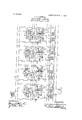
' My invention will best be understood by which shows.. diagrammatically a block-signal system arranged in accordance with my invention.
The track'rails are divided to form signal blocks A A etc.
B represents an alternating-current generator, which supplies the signal current for the track-circuits through the line-wires 6 b whichextend along the track.
C C etc., represent transformers, the primaries of which are connected to the linewires 17 b but are normally open-circuited,
as will be hereafter explained, and the sec-,
ondaries of which are connected across the rails ofa block.
-D 'D etc., represent transformers, the primaries of which are connected across the rails at the other ends of the blocks, and the secondaries of which are connected to the track-relays, which will shortly be described In the system'as shown in the drawing, the
secondary'windings of the transformer O C,
etc. and the primary windings of the transformers D D etc., form the inductive connections between the opposite rails of each block and between ad acent blocks. .The
. connection between adjacent blocks is prefof a given frequency only. I have indicated diagrammatically relays of the wel-lknown induction type, each comprising a short-circuited secondary member f carrymgLthe relay contacts, and two coperating--w1-ndings' f and f; the first'connected to the secondary of one ofthe transformers D or D, and
the other supplied independently of the track-circuits with alternating-current of the rope 'phase for producing. a torque on the short-circuited secondary member. For this purpose I have shown in series with each of the windings F a condenser but it will beunderstood that the desired phase-adjustnient may be obtainedan any other suitable manner. The rela T F 1 when ener ized closes the circuitof the operating mechanism G of the home signal H The operatingme'chaw ism, which is indicated diagrammatically, may be of any we'll-known type,and is suppliedfrom any suitable source of current indicated by the battery I Each home signal is provided with contacts 71 and k power-generator v draws up its armatures;
K represents a distant signalprovided with an operating mechanism J supplied.
from any suitable source of current L M M I etc., represent electromagnets which are arranged to be controlled by a moving train, as will hereafter be explained,
= and which, when energized, close the circuits of the transformers 0, Ct, etc., respectively. Themagnets M M etc., each have three armatures m m m and are supplied from sources of current 0, 0 etc.
"1, 2, 3, etc., represent short insulated contactrails in circuit'with "the magnets M M,
etcl, by means of'which a'moving train is enabled to control these magnets. These contact-rails are simply for the purpose of enabling a train to control the-circuits of these magnets, and any other suitable form of contact controllable by a passing train may be substituted-for thesecontact rails. When contact rails are used, they .are preferably placed between-adgacent'blocks, so as to re-' duce the'number O1 the exception of the windingsft of t 1e trackinsulated joints required. Normally, all signal circuits are 0' en, with relays, 'and consequently the signaloperating "mechanismsfrelays, and. magnets, are deenergized and occupy *the positions shown in the drawing. But when a" trainenters a block, 'for instance, the block A, it connects therail-conta'ct l to the lower rail A and therebycloses the-circuit of the magnet M? This circuit maybe traced from' the left-hand terminal to the battery 0 through the magnet winding M to the lower rail A throughthis rail and thewheels of the train to contact-rail 1, and thence to the righthand terminal of the battery. Magnet-M is consequently momentarily energized and The armature m closes amaintaining-circuit for the magnet M while armature m closes the primary circuit of the transformer- 0 This circuit may be traced from line-wire 12 through the primary 'windingof' transformer armature m to line-Wire b. Transformer C consequently supplies current to the block A and if this block is not occu ied atrain, and if no rail is broken, winding of relay F? will be energized so as to produce a torque in this relay, and cause it to close its contacts. This energizes the operating mechanism G of home-signal H which draws the signal to clear position. Then this signal reaches clear-position, its movable contact h bridges the stationary contacts, thereby closing the circuit of transformer G. This circuit may be traced from line-wire I) through the primary of transformer 0*, through contact m of magnet M and through contact h of home signal H? to line-wire b Transformer C then supplies current to the track-rails A and if this block is unoccu ied, relay winding f of relay F is energize signal H VI hen signal H clears, although thereby clearing the" primar its contacts gih en ages the stationary icon-1 tacts, it does not; 0 ose'the circuit of the next transformer in advance, since this circuit is open at the, contact m of magnet M so that t e closing of contacth is of no effect. Contact h. of signal H whenit engages thestatiom aryeffiitacts, closesth ircuit ofthe'o crating mechanism ofi distant-signal K his circuit ma traced from the'left-hand 'terminaL-o battery L through contact h of. signal H and contact h of signal H to oper-' at mechanism J and thence to the right han terminal? of the battery IE. Thus home-signals H and H and distant-signal K are clear. Home-signal H is, of course, maintained at danger, since relay F is deenergized by the presence of a train in block A and since signal H is at danger, signal K must also'remain at-danger, as its circuit cannot be closed unless signal H is clear.
Signals Hand- K having been cleared, as above described, they remain at clearun'til the train-passes from block A to A In doing so, the wheels .of thetrainlcolmect contact-rail 2 to lower rail A, thereby shortcircuiting magnet M and causing it to drop 1 itsarmatures; connect contact rail 3 ton per-railAflthereby energizing-magnet l\ and de-e'nergize relay F by short-circuiting of transformer D Relay F consequent y breaksthe circuit of'the operating'mechanism of the signal H restoring it to danger, and the contact h of this signal breaks the circuit of distant-signal K so as to cause it to go to danger also. Magnet M by dropping its armatures, breaks the circuit of transformer C at its armature m and breaks the circuit of transformer C at its I armature m. The circuit of transformer C plied to separate home and distant-signals,
it is obvious that it is equally applicable to one-army three position signals. Furthermore, Lhave shown the'apparatus diagrammatically, and it will be understood that in practice. any well known form of apparatus gmay lie-employed. Furthermore, the cironnections may be altered to suit difnditi'ons. Accordingly, I do not I desire o-lij t myself to the particular con- 'u lo dd arrangement of parts here 0M; but al'mg 1n the. appended claims to covermllmodificationswhich are within the scope ofZniy-invention.
, What I claim as new and desire to secure by Letters Patent ofthe United States, is,
I In an electrically-operated railway, track-railsdivided to form signal-blocks, in-
ductive windings cross-connecting the rails at both .ends of each block and forming with the railsa permanently-closed track circuit for each block, connections between the circuits of adjacent blocks adapted to form a return-path for the power-current, means controlled by a moving train for producing an alternatrng-current in a track-circuitahead of the train, signals normally at dan-- ger, and a signal-controlling device for each track-circuit responsive to the alternating current when supplied thereto.
2. In an electrically-operated railway,
track-rails divided to form signal-blocks, in- I ductive windings cross connecting the rails at both ends of each block and formingwith the track-rails a ermanently-closed track-circuit for each b ock; connections between the track-circuits of adjacent blocks adapted to forma return-path for the power-current,-
normally-open circuits for supplying alter- Hating-current .to the several track-circuits, means controlled by a moving train'for closing the supply-circuit for a track-circuit f ahead of the train, signals normally at dan-' ger, and a signal-controlling device for, each track-circuit responsive to the alternatingcurrent when supplied thereto. t 3. In an electrically-operated railway,
track-rails divided to form signal blocks, in-
ductive windings crossconnecting the rails at both ends of each block and forming with the track-rails a permanently-closed track-- circuit for each block, connections between the track-circuits of'adjacent blocks adapted to form a return-path for'the powerourrent, circuits for supplying alternatingcurrent to the several track-circuits, normallyopen contacts included in said supply-oil;-
cuits, electromagnets for closing said conf tacts controlled by an approaching train, signals normally at danger, and 'a signal-con trolling device for each t"ack-circuit respon sive to the alternating-current when supplied thereto.
4.. In an. electrically-operated railway, track-rails divided to form' signal-blockainductive windings cross-connecting the rails,
-at both ends of each block and forming with the track-rails a ermanently -closed trackcircuit for each b ock,'connections between the track-circuits ofad'acent blocks adapted to form a return-path or the power-current, circuits for supplying alternatingcurrent to the several track-circuits, normally-open contacts included in said supply-circuits, electromagnets for closing said contacts, circuit-connections for said magnets arranged to be closed momentarily byan ap reaching train, a maintaining-circuit for eac magnet arranged to be closed when the magnet is en ergized, signalsnormally at danger, and a signal-controlling device for each track-circuit responsive to the when'supplied thereto. v
5.111 an electrically-operated railway,
alternating-current track-rails divided'to form signal-blocks, in-.
ductive windings cross-connecting the rails at both ends of each block and forming with the tra'ck-railsa 'ermafiently-closed track' electromagnets for closing saidcontacts, 'connections arranged to be closed by a train for momentarily energizing a magnet to close the supply-circuitfor a block ahead of the train, a maintaining-circuit for the magnet arranged to be closed when the magnet is energized, connections for de-energizing the magnet when the train enters said block, a signal for the 'blocknormally at danger, and
a device controlling the signal and responsive to the alternating-current when supplied to the trackcircuit of the block,
' 6. In an electricallymperated railway,
signal-blocks, induetive windings cross-connecting the rails track-rails divided to form at both ends of each block and forming with the track-rails a ermanentlyclosed track- 'circuit 'for'each b ook, connections between the track-circuits of adjacent blocks adapted to form areturn path for the power-current, normally-open circuits for supplying alternating-current to the several track-circuits, means controlled by a moving train forclosing, the ,supply eircuit for. a track-circuit ahead of the tram, signals normally at d-anger, and a signal-controllmg relay for each track-circuit having two co-operating windings, one sup lied" with current from the track-circuit w an its supply-circuit is closed and the other normally energized by "alterhating-current supplied independently of the track-circuit.
7. In an electrically operated railway,
track-rails divided to vform signal-blocks, in'
ductive windin s cross-connecting the rails at both ends of each block and forming with the rails a ermanently closed track-circuit for each b ock, connections between the track-circuits of adjacent blocks adapted to form a return path for the power-current, normally-open circuits for supplying alternating-current to the several track-circuits, signals normally at danger adapted to give caution and clear indications, means controlled by a moving train for closing the sup-- ply-circuit for a bloclgahead of the train, and means controlled by the signal mechanism-of second block ahea 8. In an electrically operated railway,
or thepoWer-current,
transformer for each -mary normally open-circuited and its see- I ing the a block for closing the supplycircuit of a" asaaev meanin divided to form signal-blocks, in-
ductive windings cross-connecting the rails for the power-current, normally-open ciralternating-current to l the several track-circuits, means controlled cuits for supplying by a moving train for closing the supply-cirdevice res onsive to the alternatin current is cuit for a track-circuit ahead of the train, a
sup lied to the track-circuit, a signal con- ,trol ed by said device, and means controlled by the signal for closing the supply-circuit for the track-circuit next in advance.
9. In an electrically-operated railway, track-rails divided to form signal-blocks, a
block having its priondaryconnected across the rails at one end of a block, a second transformer for each block having its primary connectedacross the track-rails at the other end of the block, a signal-controlling relay for each block connected to the secondary of the second transformer, connections between the transformerwindings at adjacent ends of adjacent blocks adapted to form a path for the power-current,
and means controlled by an approaching train for closing the primary circuit of the first transformer of a block ahead of the train,
' 10. In an electrically-operated railway,
track-rails divided to form signal-blocks, a transformer for each block having its primary normally open-circuited and its secondary connected across the rails at one'end of a block, a second transformer for each block having its primary connected across the track-rails at the other end of the block, a signal-controlling relay for each block connected to the secondary of the second transformer, connections between the transformer windings at adjacent ends of adj acent blocks adapted to form a path for the powerw urrent,
means controlled an approaching train for closing the primary circuit {of the first transformer of a block ahead of the train, a signal for each block controlled by the relay, and means controlled bythe signalrfor closrimary circuit of the ffirst transformer o the block next in advance.
11. In an electrically-operated railway, track-rails divided to form signal-blocks, a transformer for each block having its primary normally open-circuited and its secondary connected across the rails at one'end ofa block, a second transformer for each 'block having'its primary connected across the track-rails at the other end of the block, a signal-controlling relay for each block connected to the secondary of the second trans;
windings at adjacent ends of adjacent blocks, adapted to form a path for the powercurrerit, an electromagnet for each block arrangei l when energized to close the primary circi wtQol the first transformer, and circuit connections for said magnet arranged to be closefl by an approaching train.
12-. 111 an electrically-imerated railway, track-rails divided to form signal-blocks, inductive windings cross-connecting the rails at both ends ofcach block and forming with the track-rails a pernianently-elosed track-v circuit for each block, connections between the track-circuits Ofad acent blocks adapted to form a returmpathfor the power-current,
circuits for supplying alternating-current to l the several track-circuits,- n0rinally-0pen contacts included in said supply-circuits,'electromaginets for closing said contacts, short insulated sections inserted in the track-rails and connected to said magnets, and a signalcontrolling device for each trm-l\"-circuit responsive to the altcrnating-current when supplied thereto.
in witness whereof, I have hereunto set my hand this 8th day of January, 1907.
. LAURENCE A. HAWKlN-S.
Witnesses:
BENJAMIN B. HULL,
HELEN Onrono.
Priority Applications (1)
| Application Number | Priority Date | Filing Date | Title |
|---|---|---|---|
| US35160507A US856467A (en) | 1907-01-10 | 1907-01-10 | Block-signal system. |
Applications Claiming Priority (1)
| Application Number | Priority Date | Filing Date | Title |
|---|---|---|---|
| US35160507A US856467A (en) | 1907-01-10 | 1907-01-10 | Block-signal system. |
Publications (1)
| Publication Number | Publication Date |
|---|---|
| US856467A true US856467A (en) | 1907-06-11 |
Family
ID=2924922
Family Applications (1)
| Application Number | Title | Priority Date | Filing Date |
|---|---|---|---|
| US35160507A Expired - Lifetime US856467A (en) | 1907-01-10 | 1907-01-10 | Block-signal system. |
Country Status (1)
| Country | Link |
|---|---|
| US (1) | US856467A (en) |
-
1907
- 1907-01-10 US US35160507A patent/US856467A/en not_active Expired - Lifetime
Similar Documents
| Publication | Publication Date | Title |
|---|---|---|
| US856467A (en) | Block-signal system. | |
| US1094894A (en) | Block-signal system. | |
| US2000166A (en) | Railway signal system | |
| US937737A (en) | Block-signal system. | |
| US3345511A (en) | Rapid transit steed control system | |
| US1692061A (en) | Railway-traffic-controlling apparatus | |
| US937439A (en) | Block-signal system. | |
| US1213161A (en) | Railway signaling system. | |
| US819322A (en) | Electric signaling. | |
| US2164331A (en) | Block system | |
| US869365A (en) | Block-signal system. | |
| US1091133A (en) | Block-signal system. | |
| US1709920A (en) | Railway-traffic-controlling apparatus | |
| US1144465A (en) | Railway-traffic-controlling system. | |
| US1405527A (en) | Railway-traffic-controlling system | |
| US856583A (en) | Block-signal system. | |
| US1837789A (en) | Railway traffic controlling apparatus | |
| US1125488A (en) | Railway signaling system. | |
| US1631808A (en) | Railway-traffic-controlling apparatus | |
| US1163973A (en) | Railway signaling system. | |
| US1152448A (en) | Railway signaling. | |
| US927404A (en) | Block-signal system. | |
| US882553A (en) | Block-signal system. | |
| US1157845A (en) | Signal system. | |
| US1428894A (en) | Railway-traffic-controlling apparatus |