US856464A - Lawn-rake. - Google Patents
Lawn-rake. Download PDFInfo
- Publication number
- US856464A US856464A US36061107A US1907360611A US856464A US 856464 A US856464 A US 856464A US 36061107 A US36061107 A US 36061107A US 1907360611 A US1907360611 A US 1907360611A US 856464 A US856464 A US 856464A
- Authority
- US
- United States
- Prior art keywords
- plate
- teeth
- rake
- lawn
- slots
- Prior art date
- Legal status (The legal status is an assumption and is not a legal conclusion. Google has not performed a legal analysis and makes no representation as to the accuracy of the status listed.)
- Expired - Lifetime
Links
Images
Classifications
-
- A—HUMAN NECESSITIES
- A01—AGRICULTURE; FORESTRY; ANIMAL HUSBANDRY; HUNTING; TRAPPING; FISHING
- A01D—HARVESTING; MOWING
- A01D7/00—Rakes
- A01D7/06—Rakes with tines specially shaped or attached
Definitions
- Our invention relates to improvements in lawn rakes and its object is to provide a rake that may be readily assembled or taken apart andwill be perfectly rigid and strong when assembled for use.
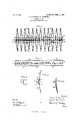
- Figure 1 is an elevation of a lawn rake assembled, but with the handle or stale removed.
- Fig. 2 is an elevation of the plate to which the teeth are secured.
- Fig. 3 is an end elevation of the same.
- Fig. 4 is the same with the teeth in place, and
- Fig. 5 is a perspective view of a tooth detached from the plate.
- edges are, preferably, turned down, practically, at right angles with the plate, as indicated at a a, to form supports for the teeth.
- the teeth are made of wire and practically of the form shown in Figs. 1 and 4 or 5 and are designated by the letter B in the several figures.
- the ends of the teeth that are connected with the plate A have offsets b that are designed to pass through the slots a in the plate and the ends I) rest on the surface of the plate so that when they are in place on the plate and the wire C is passed through the openings formed by the curves a of the partitions and the curves 1) of the teeth B, the teeth will be, thereby, held firmly and rigidly to place in the plate A so that they cannot be removed or become loose until the wire rod C is removed.
- apertures or holes a c are for the purpose of securing the handle to the head by means of screws, rivets or bolts, or any other available way, but as this feature is not essential to or in any way connected with our invention we do not deem it necessary to further illustrate this feature.
- the teeth in this rake be bifurcated, especially when designed for a lawn rake, as indicated in Figs. 1 and 5, but for other purposes it may be constructed with single teeth, as indicated in Fig. 4, as the manner of securing the teeth by the use of the curves in the plate and at the adjacent ends of the teeth with the interlaced wire rod C will render the teeth perfectly rigid and firm in the plate.
- a plate having slots through it and outwardly curved partitions between the slots, the edges of the plate turned practically at right angles with the plate, bifurcated teeth having curved portions passed through the slots forming a round .hole with the curved partitions of the plate, and short ends extending back therefrom and bearing on the surface of the plate, and a wire rod passed through said round holes, substantially as and for the purpose set forth.
Description
No. 856,464. PATENTED JUNE 11, 1907.
R. H. HAVEN & P. ROCKWELL.
LAWN RAKE.
APPLICATION FILED MAB 4. 1907.
Fig.1.
Snuento'rA Haber Haven Frank Rae/(wall Q/Vi messes airman:
rnl NORRIS Pirsns ca.. WASHINGTON, in CV UNITED STATES PATENT OFFICE.
ROBERT HILTON HAVEN AND FRANK ROCKWELL, OF GRAND RAPIDS,
' MICHIGAN.
LAWN-RAKE.
Specification of Letters Patent.
Patented. June 11, 1907 Application filed March 4, 1907. Serial No. 360,611.
1'0 all whom it WMLZ/ concern.-
Be it known that we, ROBERT HILTON HA- VEN and FRANK ROCKWELL, citizens of the United States, residing at Grand Rapids, in the. county of Kent and State of Michigan, have invented certain new and useful Improvements in Lawn-Rakes, of which the following is a specification.
Our invention relates to improvements in lawn rakes and its object is to provide a rake that may be readily assembled or taken apart andwill be perfectly rigid and strong when assembled for use.
We attain this object by the mechanism illustrated in the accompanying drawing in which Figure 1 is an elevation of a lawn rake assembled, but with the handle or stale removed. Fig. 2 is an elevation of the plate to which the teeth are secured. Fig. 3 is an end elevation of the same. Fig. 4 is the same with the teeth in place, and Fig. 5 is a perspective view of a tooth detached from the plate.
Similar letters refer to similar parts throughout the several views.
In the construction of our rake head we use a sheet metal support of practically the form shown at A in the several figures. This plat-e is perforated with a number of mortises or slots a, and the partitions between these slots are formed concavo convex, as at a, more fully illustrated in Figs. 3 and 4., for the reception of the supporting or tic wire C, and
the edges are, preferably, turned down, practically, at right angles with the plate, as indicated at a a, to form supports for the teeth.
The teeth are made of wire and practically of the form shown in Figs. 1 and 4 or 5 and are designated by the letter B in the several figures. The ends of the teeth that are connected with the plate A have offsets b that are designed to pass through the slots a in the plate and the ends I) rest on the surface of the plate so that when they are in place on the plate and the wire C is passed through the openings formed by the curves a of the partitions and the curves 1) of the teeth B, the teeth will be, thereby, held firmly and rigidly to place in the plate A so that they cannot be removed or become loose until the wire rod C is removed.
The apertures or holes a c are for the purpose of securing the handle to the head by means of screws, rivets or bolts, or any other available way, but as this feature is not essential to or in any way connected with our invention we do not deem it necessary to further illustrate this feature.
I/Ve prefer that the teeth in this rake be bifurcated, especially when designed for a lawn rake, as indicated in Figs. 1 and 5, but for other purposes it may be constructed with single teeth, as indicated in Fig. 4, as the manner of securing the teeth by the use of the curves in the plate and at the adjacent ends of the teeth with the interlaced wire rod C will render the teeth perfectly rigid and firm in the plate.
Having thus fully described our invention, what we claim as new and desire to secure by Letters Patent of the United States is:
1. The combination in a lawn rake, of a sheet .metal plate having slots for the passage of portions of teeth, an outwardly curved set of partitions between the slots, bifurcated teeth having curved bearings passed through the slots in the plate and short ends projecting beyond the slots and resting on the plate, and a wire rod passed through the opening formed by the curves in the plate and the ends of the teeth, substantially as and for the purpose set forth.
2. In combination, a plate having slots through it and outwardly curved partitions between the slots, the edges of the plate turned practically at right angles with the plate, bifurcated teeth having curved portions passed through the slots forming a round .hole with the curved partitions of the plate, and short ends extending back therefrom and bearing on the surface of the plate, and a wire rod passed through said round holes, substantially as and for the purpose set forth.
3. In combination, a plate having slots through it and outwardly curved partitions between them and the outer edges of the plate turned at right angles with the plate,
teeth having curves at one end to engage Signed at Grand Rapids, Michigan, March with the plate and form round holes with the 2 1907.
curved partitions of the plate, and having ROBERT HILTON HAVEN short ends projectin flover onto the plate, and a Wire rod pas s ed through the holes FRANK ROCKWELL formed by the curves in the teeth and in the In presence of plate, substantially as and for the purpose I. J. CILLEY, set forth. A. ALLGIER.
Priority Applications (1)
| Application Number | Priority Date | Filing Date | Title |
|---|---|---|---|
| US36061107A US856464A (en) | 1907-03-04 | 1907-03-04 | Lawn-rake. |
Applications Claiming Priority (1)
| Application Number | Priority Date | Filing Date | Title |
|---|---|---|---|
| US36061107A US856464A (en) | 1907-03-04 | 1907-03-04 | Lawn-rake. |
Publications (1)
| Publication Number | Publication Date |
|---|---|
| US856464A true US856464A (en) | 1907-06-11 |
Family
ID=2924919
Family Applications (1)
| Application Number | Title | Priority Date | Filing Date |
|---|---|---|---|
| US36061107A Expired - Lifetime US856464A (en) | 1907-03-04 | 1907-03-04 | Lawn-rake. |
Country Status (1)
| Country | Link |
|---|---|
| US (1) | US856464A (en) |
Cited By (1)
| Publication number | Priority date | Publication date | Assignee | Title |
|---|---|---|---|---|
| US2900781A (en) * | 1957-08-09 | 1959-08-25 | James T Clark | Convertible yard tools |
-
1907
- 1907-03-04 US US36061107A patent/US856464A/en not_active Expired - Lifetime
Cited By (1)
| Publication number | Priority date | Publication date | Assignee | Title |
|---|---|---|---|---|
| US2900781A (en) * | 1957-08-09 | 1959-08-25 | James T Clark | Convertible yard tools |
Similar Documents
| Publication | Publication Date | Title |
|---|---|---|
| US856464A (en) | Lawn-rake. | |
| US562491A (en) | Drawer-pull | |
| US914774A (en) | Bracket. | |
| US1172189A (en) | Drawer-head. | |
| US841550A (en) | Metallic hook. | |
| US745873A (en) | Shelf-bracket. | |
| US1084289A (en) | Toggle-bolt. | |
| US216307A (en) | Improvement in school-desks | |
| US120090A (en) | Improvement in brush and scraper for sinks | |
| US482869A (en) | Towel-rack | |
| US675917A (en) | Handle. | |
| US933714A (en) | Attachment means for binder-posts. | |
| US578755A (en) | Allen d | |
| US366809A (en) | Damper for stove-pipes | |
| US187142A (en) | Improvement in metallic lathing | |
| US556540A (en) | Crank for fishing-reels | |
| US147607A (en) | Improvement in chairs, settees | |
| US428268A (en) | Handle for vehicles | |
| US137925A (en) | Improvement in table-leaf supports | |
| US587684A (en) | Half to c | |
| US837140A (en) | Garden-rake. | |
| US577219A (en) | Christian weiss | |
| US1155039A (en) | Attachment for scrapers. | |
| US149539A (en) | Improvement in telegraph-sounders | |
| US848020A (en) | Frame and handle structure. |