US856447A - Automobile-tire. - Google Patents
Automobile-tire. Download PDFInfo
- Publication number
- US856447A US856447A US33804006A US1906338040A US856447A US 856447 A US856447 A US 856447A US 33804006 A US33804006 A US 33804006A US 1906338040 A US1906338040 A US 1906338040A US 856447 A US856447 A US 856447A
- Authority
- US
- United States
- Prior art keywords
- rim
- tire
- rim member
- automobile
- members
- Prior art date
- Legal status (The legal status is an assumption and is not a legal conclusion. Google has not performed a legal analysis and makes no representation as to the accuracy of the status listed.)
- Expired - Lifetime
Links
- 229910000831 Steel Inorganic materials 0.000 description 4
- 239000010959 steel Substances 0.000 description 4
- 238000010276 construction Methods 0.000 description 2
- 239000000463 material Substances 0.000 description 2
- 239000007787 solid Substances 0.000 description 2
- 229920001875 Ebonite Polymers 0.000 description 1
- 239000004411 aluminium Substances 0.000 description 1
- 229910052782 aluminium Inorganic materials 0.000 description 1
- XAGFODPZIPBFFR-UHFFFAOYSA-N aluminium Chemical compound [Al] XAGFODPZIPBFFR-UHFFFAOYSA-N 0.000 description 1
- 239000000945 filler Substances 0.000 description 1
- 239000011121 hardwood Substances 0.000 description 1
- 229910052751 metal Inorganic materials 0.000 description 1
- 239000002184 metal Substances 0.000 description 1
- 239000004576 sand Substances 0.000 description 1
- 239000002023 wood Substances 0.000 description 1
Images
Classifications
-
- B—PERFORMING OPERATIONS; TRANSPORTING
- B60—VEHICLES IN GENERAL
- B60B—VEHICLE WHEELS; CASTORS; AXLES FOR WHEELS OR CASTORS; INCREASING WHEEL ADHESION
- B60B9/00—Wheels of high resiliency, e.g. with conical interacting pressure-surfaces
- B60B9/18—Wheels of high resiliency, e.g. with conical interacting pressure-surfaces using fluid
- B60B9/20—Wheels of high resiliency, e.g. with conical interacting pressure-surfaces using fluid in rings concentric with wheel axis
Definitions
- Invention relates to yieldable tires for automobiles and like vehicles, and has for its object to improve the construction and'increasey the efficiency of devices of this character.
- Figure 1 is a transverse section of the rim of an automobile wheel and for th'e purpose of this'description, these parts willbe'referred to as above noted.
- the main ⁇ base rim member is represented at 1Q, preferably of s teel and with sockets 11 at suitable intervals to receive spokes 12, if the device is applied to rims in which spokes are emp oyed.
- the rimy is for-med with its inner portion semi-circular and with its sides 'extending parallel'for a distance at their terminals as illustrated at 13 and 14.- K
- the intermediate rim preferably of wood, and -formed in two parts 15 and 16, and divided circumferentially of the rim and at one side of its center-as represented at 17, the two parts 15-16 being provided at suitable intervals with studs or pins 18, to prevent the two-part intermediate rim from creeping under the severe strain to which they will be subJected.
- thel 'invention consists incertain novel features of construction, as hereafter shown and de- Patented June 1 1, 1907.
- he two-part intermediate rim 15-16 is rovlded with an encircling channel 19 in W 'ch an inflatable tire memberk 20 bears, as hereafter explained.
- 'lhe smaller intermediate rim member 16 is provided with a sheet metal lining 21 preferably of steel, to increase the strength of the device.
- the two-part tire member 15-16 is further secured by bolts 24 at suitable intervals.
- t 1e outer rim member 22 Fitting between the arallel sides 13-14 of the outer steel rim is t 1e outer rim member 22 of aluminium, hard wood, or like suitable material, and provided with an inner channel 23 for bearing over the outer face of the inflatable tire member 20.
- the outer face of the two-part rim member 15-16 is inclined inwardly, and the inner face of the rim member 22 is correspondingly inclined, and provided with pins 25 at suitable intervals fltting into sockets26 within the two-part rim member '15-16, the pins being surrounded by springs 27, so that the rim member 22 isyieldable relative to the ,other parts of the structure.
- the outer face of the rim member 22 is y provided with axplurality of channels, a cenltral channel 28 to receive the solid rubber tire member- 29, and smaller channels 30-31 at each side of the central channel 28 to receive smaller rubber tire members E32-33, the larger central tire member rojecting for some distance beyond the smailer tire members 32-33, theobject to be hereafter explained.
- the rim member 22 rojects at its edges beyond the centers of tiel tire members at 34--35, .to assist in holding them in place upon the rim member 22.
- sockets being rigidly embedded in the rim IOO '43 of the bolts embedded in suitable recesses in their chocks.
- the heads 40-'43 of the bolts are provided with wrench heads or screw driver recessesto enable them to be operated.
- the chocks 38-41 extend laterally for a distance over the tire ⁇ members 29, 32 and 33 beyond ⁇ their center lines, as shown, and thus serve to bind the tire members upon the rim member 22, in co-a'ction with the inwardly extending edges 34--35, as shown in. Fig. 1.
- chocks 38-41 maybe em# ployed as required, and spaced at suitable distances apart, with the spaces between the cliocks .occupied by filler members of suitable material such as hard rubber, ⁇ as represented Aat 44 in Fig. 2.
- the inner inflatable tire 'member 2.0 to-- which are subjected to the greatest wear, and' are liable to be broken are the relatively cheap portions 29, 32- and 33.
- a vehicle wheel comprising a channeled rim, an intermediate rim member seated in the channeled rim and provided with a eripheral groove and with sockets disposedp at intervals on opposite sides of saidgroove, an outer rim member encircling and s aced from the intermediate rim member and) rovided on its inner face with a groove eXtend outer and intermediate rimvmembers and seated in the grooves, studs projecting inwardly from the inner face of the outer rim member and slidably disposed in the several sockets, compressible springs arranged on the studs 'between' the rim members, and a tire applied to the outer face of the outer rim member.
- OuterTirn member encircling said rim and spaced from the bottom wall of the latter, cushioning means interposed between the rim and outer rirnmember, a plurality of spaced tires ap lied to the outer face of the latter, threade sockets embedded in the rim member at -intervals and on rines between the spaced tires,retaining blocks itted between and engaging the opposing walls of the spaced 'tires at points in line with the sockets, and
- a channeled rim having a filling, an outer rinrmember applied aroundls'aid rim and spaced at its inner face from the periphery of the filling, cushioning Y members interposed between the filling and rim member for yieldably supporting the latter, a main central tire applied to the rim member and forming the thread thereof, and auxiliary tires apphed to the rim member respectively at opposite sides of the main tire, said auxiliary tires being disposed in the plane of a circle of smaller diameter than that of the maintire. .Y
- a channeled rim In a vehicle wheel, a channeled rim, an inner rim member seated in said channel and comprising .apair ⁇ of separable sections, transversely-projectingpins carried by one of the j sections and entering sockets provided in the other to fix the sections against relative creepnesses.
Landscapes
- Engineering & Computer Science (AREA)
- Mechanical Engineering (AREA)
- Tires In General (AREA)
Description
PATBNTED JUNE 1l, 1907.
F. D. G. COOKa AUTOMOBILE TIRE.
APPLICATION FILED 00128, 1906.
lll/111111111 0 ff A k f wml p.v u a y V UNITED ysT.,iTns PATENTV onirica..
FREDERICK D. G. COOK, OF CHIPPEFVA FALLS, WISCONSIN.
AUTOMOBILE-TIRE.
No. ec,447.
To all -whom it may con/cern:
Be it known that I, FREDERICK D. G. Coon, a cltizen of the United States, residing at yChippewa. Falls, in the county of Chippewa and State of Wisconsin, have invented certain ne'wj and useful Improvements in Automobile- Tires and I do declare the followinglto be a full, clear, and exact description of the inventon such as will enable others skilled in the art to which appertainsto make and use the same.
Invention relates to yieldable tires for automobiles and like vehicles, and has for its object to improve the construction and'increasey the efficiency of devices of this character.
scribed and specically pointed out in the claims,
In vthe accompanying drawings forming a part of this specification and inwhich correspending parts are denoted by like characters, is illustrated the preferredform `of the embodiment of the inventioncapable of car- 'rymg Athe same into practical operation.
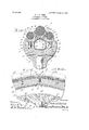
In the drawings, Figure 1 is a transverse section of the rim of an automobile wheel and for th'e purpose of this'description, these parts willbe'referred to as above noted. The main `base rim member is represented at 1Q, preferably of s teel and with sockets 11 at suitable intervals to receive spokes 12, if the device is applied to rims in which spokes are emp oyed.
The rimy is for-med with its inner portion semi-circular and with its sides 'extending parallel'for a distance at their terminals as illustrated at 13 and 14.- K
Fitting within the steel rim 10, is the intermediate rim, preferably of wood, and -formed in two parts 15 and 16, and divided circumferentially of the rim and at one side of its center-as represented at 17, the two parts 15-16 being provided at suitable intervals with studs or pins 18, to prevent the two-part intermediate rim from creeping under the severe strain to which they will be subJected.`
Specicaton of Letters Patent.
Application met october 8,1906. serial No. 338,0420.
Withl these and otherobjects in view, thel 'invention consists incertain novel features of construction, as hereafter shown and de- Patented June 1 1, 1907.
' T he two-part intermediate rim 15-16 is rovlded with an encircling channel 19 in W 'ch an inflatable tire memberk 20 bears, as hereafter explained. 'lhe smaller intermediate rim member 16 is provided with a sheet metal lining 21 preferably of steel, to increase the strength of the device. The two-part tire member 15-16 is further secured by bolts 24 at suitable intervals.
Fitting between the arallel sides 13-14 of the outer steel rim is t 1e outer rim member 22 of aluminium, hard wood, or like suitable material, and provided with an inner channel 23 for bearing over the outer face of the inflatable tire member 20.
The outer face of the two-part rim member 15-16 is inclined inwardly, and the inner face of the rim member 22 is correspondingly inclined, and provided with pins 25 at suitable intervals fltting into sockets26 within the two-part rim member '15-16, the pins being surrounded by springs 27, so that the rim member 22 isyieldable relative to the ,other parts of the structure.
The outer face of the rim member 22 is y provided with axplurality of channels, a cenltral channel 28 to receive the solid rubber tire member- 29, and smaller channels 30-31 at each side of the central channel 28 to receive smaller rubber tire members E32-33, the larger central tire member rojecting for some distance beyond the smailer tire members 32-33, theobject to be hereafter explained.
The rim member 22 rojects at its edges beyond the centers of tiel tire members at 34--35, .to assist in holding them in place upon the rim member 22. v
The ortions of the rim member 22 which comes etween the tire member 29 and tire member 32, and between the tire member 29 and tire member 33 are less in extent than the edges 311-35, and are rovided at these points with threaded soc ets 36-37, the
sockets being rigidly embedded in the rim IOO '43 of the bolts embedded in suitable recesses in their chocks. The heads 40-'43 of the bolts are provided with wrench heads or screw driver recessesto enable them to be operated.
The chocks 38-41 extend laterally for a distance over the tire` members 29, 32 and 33 beyond` their center lines, as shown, and thus serve to bind the tire members upon the rim member 22, in co-a'ction with the inwardly extending edges 34--35, as shown in. Fig. 1.
As many of the chocks 38-41 maybe em# ployed as required, and spaced at suitable distances apart, with the spaces between the cliocks .occupied by filler members of suitable material such as hard rubber,` as represented Aat 44 in Fig. 2.
By this arrangement, it will beobvious that with a device thus constructed and a plied, the pressure will be borne very large y y the central solid rubber tire member 29 when running upon hard pavements or hard roads', but when running over soft roads or' in sand and. likematerial. the sinking of the tire therein will c ause the'sm-ailer flanking tire members 32-33 to bear upon the'road, and thus not only increase the tractive force, but likewise prevent the tire fromV sinking into the ground.
The inner inflatable tire 'member 2.0 to-- which are subjected to the greatest wear, and' are liable to be broken are the relatively cheap portions 29, 32- and 33.
It will be noticed that it will be im ossible to puncture this improved tire, as t e only part subject to puncture is the iniiatable member 20, which is effectually protected by the relatively heavy-rim member 22 and a steel rim member 10.
Having thus described the invention, what is claimed is l. A vehicle wheel comprising a channeled rim, an intermediate rim member seated in the channeled rim and provided with a eripheral groove and with sockets disposedp at intervals on opposite sides of saidgroove, an outer rim member encircling and s aced from the intermediate rim member and) rovided on its inner face with a groove eXtend outer and intermediate rimvmembers and seated in the grooves, studs projecting inwardly from the inner face of the outer rim member and slidably disposed in the several sockets, compressible springs arranged on the studs 'between' the rim members, and a tire applied to the outer face of the outer rim member.
2. In a vehicle wheel, a channeled'rim, an
OuterTirn member encircling said rim and spaced from the bottom wall of the latter, cushioning means interposed between the rim and outer rirnmember, a plurality of spaced tires ap lied to the outer face of the latter, threade sockets embedded in the rim member at -intervals and on rines between the spaced tires,retaining blocks itted between and engaging the opposing walls of the spaced 'tires at points in line with the sockets, and
clamping screws entered through theretaining blocks and engaged with the several sockets. v
3. In a vehicle wheel, a channeled rim having a filling, an outer rinrmember applied aroundls'aid rim and spaced at its inner face from the periphery of the filling, cushioning Y members interposed between the filling and rim member for yieldably supporting the latter, a main central tire applied to the rim member and forming the thread thereof, and auxiliary tires apphed to the rim member respectively at opposite sides of the main tire, said auxiliary tires being disposed in the plane of a circle of smaller diameter than that of the maintire. .Y
4. In a vehicle wheel, a channeled rim, an inner rim member seated in said channel and comprising .apair` of separable sections, transversely-projectingpins carried by one of the j sections and entering sockets provided in the other to fix the sections against relative creepnesses.
' FREDERICK D. G. COOK. Witnesses:
DAYTON E. Coon, S. H. COOK.
TOO
IIO
Priority Applications (1)
| Application Number | Priority Date | Filing Date | Title |
|---|---|---|---|
| US33804006A US856447A (en) | 1906-10-08 | 1906-10-08 | Automobile-tire. |
Applications Claiming Priority (1)
| Application Number | Priority Date | Filing Date | Title |
|---|---|---|---|
| US33804006A US856447A (en) | 1906-10-08 | 1906-10-08 | Automobile-tire. |
Publications (1)
| Publication Number | Publication Date |
|---|---|
| US856447A true US856447A (en) | 1907-06-11 |
Family
ID=2924902
Family Applications (1)
| Application Number | Title | Priority Date | Filing Date |
|---|---|---|---|
| US33804006A Expired - Lifetime US856447A (en) | 1906-10-08 | 1906-10-08 | Automobile-tire. |
Country Status (1)
| Country | Link |
|---|---|
| US (1) | US856447A (en) |
-
1906
- 1906-10-08 US US33804006A patent/US856447A/en not_active Expired - Lifetime
Similar Documents
| Publication | Publication Date | Title |
|---|---|---|
| US856447A (en) | Automobile-tire. | |
| US1067744A (en) | Demountable-rim. | |
| US1223788A (en) | Combined cushioning and fastening device for tires. | |
| US1192348A (en) | Wheel structure. | |
| US1147111A (en) | Tire for vehicle-wheels. | |
| US1209130A (en) | Tire-protector. | |
| US812893A (en) | Wheel-tire. | |
| US807633A (en) | Tire. | |
| US1197254A (en) | Spring-wheel. | |
| US775361A (en) | Rubber tire. | |
| US873841A (en) | Vehicle-wheel. | |
| US770348A (en) | Cuthbert buenett | |
| US1248947A (en) | Emergency-tire. | |
| US1436793A (en) | Cushioned wheel rim | |
| US1355011A (en) | Resilient tire | |
| US1115566A (en) | Wheel-tire. | |
| US1152543A (en) | Demountable felly-band for vehicle-wheels. | |
| US670924A (en) | Detachable tread-shoe for traction-wheels. | |
| US752891A (en) | Rubber tire | |
| US1135876A (en) | Tire for vehicles. | |
| US1032286A (en) | Wheel-rim. | |
| US959706A (en) | Vehicle-wheel. | |
| US1316944A (en) | Vehicle-wheel attachment | |
| US993332A (en) | Vehicle-wheel. | |
| US1345281A (en) | Vehicle-wheel |