US856442A - Track-fastening device. - Google Patents
Track-fastening device. Download PDFInfo
- Publication number
- US856442A US856442A US32906406A US1906329064A US856442A US 856442 A US856442 A US 856442A US 32906406 A US32906406 A US 32906406A US 1906329064 A US1906329064 A US 1906329064A US 856442 A US856442 A US 856442A
- Authority
- US
- United States
- Prior art keywords
- plate
- rails
- track
- fastening device
- cross tie
- Prior art date
- Legal status (The legal status is an assumption and is not a legal conclusion. Google has not performed a legal analysis and makes no representation as to the accuracy of the status listed.)
- Expired - Lifetime
Links
- 238000010276 construction Methods 0.000 description 4
- 239000002184 metal Substances 0.000 description 2
- 101100481408 Danio rerio tie2 gene Proteins 0.000 description 1
- 101100481410 Mus musculus Tek gene Proteins 0.000 description 1
- 229910000831 Steel Inorganic materials 0.000 description 1
- 238000005452 bending Methods 0.000 description 1
- 230000008602 contraction Effects 0.000 description 1
- 239000010959 steel Substances 0.000 description 1
Images
Classifications
-
- E—FIXED CONSTRUCTIONS
- E01—CONSTRUCTION OF ROADS, RAILWAYS, OR BRIDGES
- E01B—PERMANENT WAY; PERMANENT-WAY TOOLS; MACHINES FOR MAKING RAILWAYS OF ALL KINDS
- E01B5/00—Rails; Guard rails; Distance-keeping means for them
- E01B5/16—Distance keepers
Definitions
- the invention relates to improvements in track fastening devices.
- the Object of the present invention is to improve the construction of track fastening devices, and to provide a simple, inexpensive and efficient track fastening device of great strength and durability designed for use on wooden cross ties, and adapted to avoid the wreeks due to the spreading of rails and capable of effectually preventing the rails from spreading under the heaviest engines.
- a further Object of the invention is to provide a track fast'ening device of this character adapted to protect a wooden cross tie, and eapable of materially increasing the life of the latter and of effectually preventing the rails from spreading, should the cross ties rot at the ends.
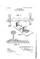
- FIG. 1 is a plan view of a track fastening device, constructed in accordance with this invention.
- Fig. 2 is a sectional view of one of the devices.
- Fig. 3 is a detail Perspective view of one of the devices, the clamping aws being arranged vertically.
- l designates a metallic plate, designed to be arranged on the upper face of a wooden cross tie 2, and constructed preferably of steel of three-eighths of an inch in thiekness, but the size and Weight of this rail-connecting and tie protecting plate may be varied to seeure the desired strength.
- the plate '1 which extends entirely across the space between the rails 3 of a track, is provided at its ends with spaced rail engaging clamping jaws 4, which are formed :integral with the plate.
- the clamping lips or jaws which are arranged in pairs, are substantially rectangular, and are formed by partially severing the metal, and then bending the partially severed portions upward into a vertical position, as illustrated in Fig. 3 of the drawing.
- the outer li p or aw of each pair is connected with the plate at the enter side of the opening 5, formed by cutting such lip or j aw from the said plate, and the other lip or j aw is connected with the plate 1 at the inner side of the Opening 6.
- the plate 1 is arranged llat upon the upper face of the cross tie, and the lower face of the said plate may be corrugated, or otherwise roughened, so that the weight of a heavy engine or trainwill partially enbed the plate in the upper face of the cross tie, and thereby effectually prevent the plate from accidentally slipping.
- the plate is provided with central openings for the reception of spikes 8, which secure the plate to the cross tie before the rails are placed in position.
- the rails are placed upon the plate in the space between the vertically disposed clamping jaws or lips 4, the latter are bent downwardly and inwardly into engagement with the bottom ilanges of the rails, whereby the latter will be securely clamped in an upright position, and will be e'll'ectually prevented fromaccidentally spreading.
- This construction Will entirely eliminate the wrecks due to the spreading of the rails.
- the spikes 9 are driven through the ends of the plate at the inner and outer edges of the rails. The heads of the spikes engage the bottom llanges of the rails, and serve to hold the latter and at the same time fasten the ends of the plate to the cross tie.
- the central spikes 8 which may be either one or two in number, will hold the plate to the tie, even should the end spikes 9 loosen, through partial decay of the end portions of the cross tie, as the end portions of the cross tie are subject to earlier decay than the central portions.
- the clamping jaws er lips do not interfere with the creeping or expansion and contraction of the rails due to the changes in tenperature.
- the track fastening device may be arranged at any dcsired points along a track, but only two are necessary between the j oints of 35 foot rails, and only one on every sixth tie on curves.
- the deVice is made twice the Width of the plate, l provided at its ends with integral clamping which is used between the joints, and two jaws formed byslitting theend portions of the sets of lips or j aws are employed at each end of such enlargement plates. As this is a mere duplication of that shown in the drawing, illustration of such change is deemed unnecessary.
Landscapes
- Engineering & Computer Science (AREA)
- Mechanical Engineering (AREA)
- Architecture (AREA)
- Civil Engineering (AREA)
- Structural Engineering (AREA)
- Joining Of Building Structures In Genera (AREA)
- Railway Tracks (AREA)
Description
No. 856,442. V PATENTED JUNE 11, 1907. L. WMAN. TRACK F NINGDEVICE.
AAAAAAAAAAAAAAAAA UG. 3. 1908.
LEWIS H. BOWMAN, OF LOS ANGELES, CMJIF(`)RNIA.
TRACK-FASTENING DEVlCE.
Specifieation of Letters Patent.
Patented June 11, 1907.
Application filed August 3.1906. Serial No. 329,064.
To Z *Le/tom it may concern:
Be it known that I, Lnwrs II. BOWMAN, a citizenof the United States, residing at Los Angeles, in the county of Los Angeles and State of California, have invented a new and useful Track-Fastening Device, of which the following is a specifieation.
The invention relates to improvements in track fastening devices.
The Object of the present invention is to improve the construction of track fastening devices, and to provide a simple, inexpensive and efficient track fastening device of great strength and durability designed for use on wooden cross ties, and adapted to avoid the wreeks due to the spreading of rails and capable of effectually preventing the rails from spreading under the heaviest engines.
A further Object of the invention is to provide a track fast'ening device of this character adapted to protect a wooden cross tie, and eapable of materially increasing the life of the latter and of effectually preventing the rails from spreading, should the cross ties rot at the ends.
With these and other objects in view, the invention consists in the construction and novel combination of parts hereinafter fully described, illustrated in the acconipanying drawing, and pointed out in the claims hereto appended; it being understood that various changes in the form, proportion, size and minor details of construction, within the scope of the claims, may be resorted to without departing from the spirit or sacrificing any of the advantages of the invention.
In the drawingz-Figure 1 is a plan view of a track fastening device, constructed in accordance with this invention. Fig. 2 is a sectional view of one of the devices. Fig. 3 is a detail Perspective view of one of the devices, the clamping aws being arranged vertically.
Like numerals of reference designate corresponding parts in all the figures of the drawing.
l designates a metallic plate, designed to be arranged on the upper face of a wooden cross tie 2, and constructed preferably of steel of three-eighths of an inch in thiekness, but the size and Weight of this rail-connecting and tie protecting plate may be varied to seeure the desired strength. The plate '1, which extends entirely across the space between the rails 3 of a track, is provided at its ends with spaced rail engaging clamping jaws 4, which are formed :integral with the plate.
The clamping lips or jaws, which are arranged in pairs, are substantially rectangular, and are formed by partially severing the metal, and then bending the partially severed portions upward into a vertical position, as illustrated in Fig. 3 of the drawing. The outer li p or aw of each pair is connected with the plate at the enter side of the opening 5, formed by cutting such lip or j aw from the said plate, and the other lip or j aw is connected with the plate 1 at the inner side of the Opening 6. By this arrangement, the open ings in the ends of the plate 1 are covered by the rails, when the latter are in position.
The plate 1 is arranged llat upon the upper face of the cross tie, and the lower face of the said plate may be corrugated, or otherwise roughened, so that the weight of a heavy engine or trainwill partially enbed the plate in the upper face of the cross tie, and thereby effectually prevent the plate from accidentally slipping. The plate is provided with central openings for the reception of spikes 8, which secure the plate to the cross tie before the rails are placed in position. After the rails are placed upon the plate in the space between the vertically disposed clamping jaws or lips 4, the latter are bent downwardly and inwardly into engagement with the bottom ilanges of the rails, whereby the latter will be securely clamped in an upright position, and will be e'll'ectually prevented fromaccidentally spreading. This construction Will entirely eliminate the wrecks due to the spreading of the rails. After the rails have been clamped by the lips or jaws i, the spikes 9 are driven through the ends of the plate at the inner and outer edges of the rails. The heads of the spikes engage the bottom llanges of the rails, and serve to hold the latter and at the same time fasten the ends of the plate to the cross tie. The central spikes 8, which may be either one or two in number, will hold the plate to the tie, even should the end spikes 9 loosen, through partial decay of the end portions of the cross tie, as the end portions of the cross tie are subject to earlier decay than the central portions. The clamping jaws er lips do not interfere with the creeping or expansion and contraction of the rails due to the changes in tenperature.
The track fastening device may be arranged at any dcsired points along a track, but only two are necessary between the j oints of 35 foot rails, and only one on every sixth tie on curves. At the joints of the rails the deVice is made twice the Width of the plate, l provided at its ends with integral clamping which is used between the joints, and two jaws formed byslitting theend portions of the sets of lips or j aws are employed at each end of such enlargement plates. As this is a mere duplication of that shown in the drawing, illustration of such change is deemed unnecessary.
Having thus fully described my invention, what I claim as new and desire to secure by Letters Patent, is 1- The combination with a wooden cross tie, of a continuous flat tie-protecting and railconnecting plate constructed of a single piece of metal and arranged on and secured to the upper face of the cross tie at the central 'portion thereof, said plate being extended beyond the outer side of each of the rails and plate, said jaws being arranged in pairs and adapted to be bent downward into engagement with the bottom flanges of the rails at the inner and outer edges thereof, and spikes located at the opposite side edges of the jaws for securing both the rails and the plate to the ends of the cross tie.
In testimony, that I claim the foregoing as my own, Ihave hereto aifixed my signature in the presence of two witnesses.
LEVVIS H. BOVVMAN.
Witnesses J. D. BUCKWALTER, JEssE SIMMONS.-
Priority Applications (1)
| Application Number | Priority Date | Filing Date | Title |
|---|---|---|---|
| US32906406A US856442A (en) | 1906-08-03 | 1906-08-03 | Track-fastening device. |
Applications Claiming Priority (1)
| Application Number | Priority Date | Filing Date | Title |
|---|---|---|---|
| US32906406A US856442A (en) | 1906-08-03 | 1906-08-03 | Track-fastening device. |
Publications (1)
| Publication Number | Publication Date |
|---|---|
| US856442A true US856442A (en) | 1907-06-11 |
Family
ID=2924897
Family Applications (1)
| Application Number | Title | Priority Date | Filing Date |
|---|---|---|---|
| US32906406A Expired - Lifetime US856442A (en) | 1906-08-03 | 1906-08-03 | Track-fastening device. |
Country Status (1)
| Country | Link |
|---|---|
| US (1) | US856442A (en) |
-
1906
- 1906-08-03 US US32906406A patent/US856442A/en not_active Expired - Lifetime
Similar Documents
| Publication | Publication Date | Title |
|---|---|---|
| US856442A (en) | Track-fastening device. | |
| US1070270A (en) | Railway-tie. | |
| US1029426A (en) | Device for securing rails to ties. | |
| US1116446A (en) | Railway construction. | |
| US1159842A (en) | Railroad-spike-securing device. | |
| US948375A (en) | Rail-clip. | |
| US737701A (en) | Tie-plate and rail-brace. | |
| US717088A (en) | Fish-plate and noise-reducing device for railways. | |
| US723439A (en) | Fish-plate joint for railway-rails. | |
| US1206055A (en) | Metallic tie and rail-fastener. | |
| US1028432A (en) | Railway-tie and fastener. | |
| US1102725A (en) | Combined rail-brace and tie-plate. | |
| US963294A (en) | Combined rail chair and brace. | |
| US763640A (en) | Rail-support. | |
| US744623A (en) | Railway-rail clamp. | |
| US1155868A (en) | Combined rail-brace and anchor tie-plate. | |
| US988408A (en) | Rail tie and fastener. | |
| US1174298A (en) | Perforated metallic railroad-tie. | |
| US835456A (en) | Tie-bar. | |
| US813611A (en) | Metallic railway-tie. | |
| US462716A (en) | Railway-tie and rail-securing device | |
| US1209823A (en) | Metallic rail-tie cover. | |
| US1048652A (en) | Rail-fastening device. | |
| US1066886A (en) | Rail-fastener. | |
| US739026A (en) | Rail-chair. |