US856441A - Maximum-demand indicator. - Google Patents
Maximum-demand indicator. Download PDFInfo
- Publication number
- US856441A US856441A US34320806A US1906343208A US856441A US 856441 A US856441 A US 856441A US 34320806 A US34320806 A US 34320806A US 1906343208 A US1906343208 A US 1906343208A US 856441 A US856441 A US 856441A
- Authority
- US
- United States
- Prior art keywords
- tube
- bulb
- liquid
- gas
- arm
- Prior art date
- Legal status (The legal status is an assumption and is not a legal conclusion. Google has not performed a legal analysis and makes no representation as to the accuracy of the status listed.)
- Expired - Lifetime
Links
- 239000007788 liquid Substances 0.000 description 71
- 239000004020 conductor Substances 0.000 description 26
- 230000003405 preventing effect Effects 0.000 description 24
- 230000006835 compression Effects 0.000 description 15
- 238000007906 compression Methods 0.000 description 15
- 241000192308 Agrostis hyemalis Species 0.000 description 4
- 238000010438 heat treatment Methods 0.000 description 4
- 238000010276 construction Methods 0.000 description 2
- 230000005574 cross-species transmission Effects 0.000 description 2
- 230000000694 effects Effects 0.000 description 2
- 239000011521 glass Substances 0.000 description 2
- 238000004519 manufacturing process Methods 0.000 description 2
- 230000000630 rising effect Effects 0.000 description 2
- 238000002474 experimental method Methods 0.000 description 1
- 239000011810 insulating material Substances 0.000 description 1
- 239000000463 material Substances 0.000 description 1
- 239000002023 wood Substances 0.000 description 1
Images
Classifications
-
- G—PHYSICS
- G01—MEASURING; TESTING
- G01R—MEASURING ELECTRIC VARIABLES; MEASURING MAGNETIC VARIABLES
- G01R11/00—Electromechanical arrangements for measuring time integral of electric power or current, e.g. of consumption
- G01R11/56—Special tariff meters
- G01R11/60—Subtraction meters; Meters measuring maximum or minimum load hours
Definitions
- My invention relates to maximum-demand [O indicators, and particularly to that type of indicator in which a conductor, carrying t he current to be measured, heats a portion of a tube, thereby expanding the gas therein which, in expanding, causes a liquid in the tube to spillover into an adjacent receptacle beside which is a scale indicating the current that corresponds to the amount of liquid spilled over.
- An instrument of this kind is covered by the patent to ⁇ Vright, No.
- This instrument in its usual form generally comprises a U-shaped tube containing a liquid 0 and terminating at each end in a bulb, a currentcarrying conductor located adjacent one of said bulbs, and a gage tube connected with one arm of the U-tube for receiving the liquid forced out of the U-tube by the expan- 3 5 sion of the gas in the bulb to which the heat ing conductor is applied.
- the bubbles will evcntuallyrise through the constrictions into the bulbs, but this action is not always instantaneous when the tube is brought back to its normal position after resetting.
- the object of my invention is to provide an improved tube which will not be open to the above-mentioned objections.
- my invention consists in applying to a tube for use in'instruments of this kind, means for absolutely pre venting gas from rising into the base of the U-tubc during resetting of the instrument.
- my invention consists in placing in one or both arms of the U-tubc a liquid seal which will prevent the gas in one or both of the bulbs from rising into the base oi the U-tube during resetting.
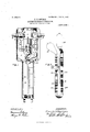
- Fig. 1 is an elevation of an instrument in which my invention is embodied, the cover of the instrument being removed in order to show the working parts
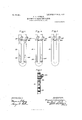
- Fig. 2 is a back elevation of the tube showing the preferred form of my invention
- Figs. 3, 4 and 5 are back views of portions of tubes showing modified forms thereof
- Fig. 6 is a sec tional elevation of a portion of a tube showing the liquid seal and constriction.
- Fig. 1 the casing in which the working parts of the instrument are contained is indicated at 1.
- the cover which is not shown, is hinged to the lower end of this casing and is of the same general form.
- a pane of glass set in the cover allows the scale of the instrument to be seen when the cover is closed.
- Mounted in the inside, of the casing is a block of insulating material 2 to which are attached the terminals 3 and 4.
- the ends of the wires 5 and 6, which carry the current to and form the indicator, pass through insulated bushings 7 in the sides of the casing and are held in holes in the terminals 3 and 4 by means of the screws 8, as is clearly shown in Fig. 1.
- the members 9 and 10 which serve both as conductors, as will be hereafter explained, and as hinge members for connecting the supporting base 11 with the casing of the instrument.
- This base 11 which may be made of wood or some other non-conducting material, is connected to the members 9 and 10 by means of screws, as is clearly shown.
- the glass tube which is mounted upon the back 11, is held thereon by the strap 12, as shown in Fig. l, or in any other suitable manner.
- This tube is more clearly shown in Fig. 2 and consists in general of a U-shaped tube 13 provided atone end with the bulb 14 and at the other end with the bulb 15, a gage tube 16 being attached to the U-tube at a point slightly below the bulb 15.
- This U- tube is filled with a suitable liquid to the levels indicated in Figs. 1 and 2.
- Surrounding the bulb 14 is a thin heating strip 17 of some suitable material electrically connected with the members 9 and 10 by the conductors 18 and 19, as shown in Fig. 1.
- the constrictions whose function, as above explained, is to hold back the main body of the liquid when the tube is inverted during resetting or while being shipped, are shown at 21 and 22. These are easily formed by drawing down the tube at these points.
- the branch tube 26 extends from what is the back side of the U-tube when this is mounted in the casing. It will, therefore, be seen that when the base 11 carrying the tube is tilted upward inorder to allow the liquid in the gage tube to drain back into the bulb 15, the branch tube 26 will always be on the under side of the U-tube and will, therefore, remain filled with liquid. This liquid in the branch tube 26 will cover the end of the bent tube 25, thereby preventing any gas from passing upward from the bulb 15 beyond. this point while the tube is inverted.
- Fig. 4 shows another form of tube that will give satisfaction.
- the constrictions shown in Figs. 2 and 3 are omitted, the liquid seals being depended upon to perform the function of the constrictions as well as their own regular function.
- the effect is obviously the same as that produced by constrictions in the U- tube itself.
- Tubes 3 and 4 are, therefore, just as satisfactory as the form of tube shown in Fig. 2, and the latter form is only preferred out of consideration for ease in manufacture.
- a main tube containing a liquid and terminating at each end in a bulb, a curreiit-carrying conductor located adjacent one of said bulbs, a gage tube connected with the main tube, and a liquid seal in the main tube for preventing the gas in a bulb from passing into the main tube.
- main tube containing a liquid and terminat' ing at each end in a bulb, a current-carrying conductor located adjacent one of said bulbs, a tube connected with said main tube, a gas trap in said main tube, and a liquid seal in said main tube for preventing the gas in a bulb from passing into the main tube.
- a main tube containing a liquid and having constrictions therein and terminating at each end in a bulb, a currelit-carrying conductor located adjacent one of said bulbs, a gage tube connected with said main tube, and a liquid seal in the main tube for preventing the gas in a bulb from passing into the main tube.
- a main tube containing a liquid and having constrictions therein and terminating at each end in a bulb, a current-carrying conductor located adjacent one of said bulbs, a gage tube connected with said main tube, a gas trap in said main tube, and a liquid seal in the main tube for preventing the gas in a bulb from passing into the main tube.
- a U- shaped tube containing a liquid and terminating at each end in a bulb, a c1u'rent-carryiug conductor located adjacent one of said bulbs, a gage tube connected with one arm of the U-tube, and a liquid seal in the U-tube for preventing the gas in one bulb from passing into the U-tube.
- a U- shaped tube containing a liquid and terminating at each end in a bulb, a current-earryiug conductor located adjacent one of said bulbs, a gage tube connected with one arm of the U-tube, and a liquid seal in the U-tube on the compression side thereof for preventing the gas on that side from passing into the U- tube.
- a U- IlO shaped tube containing a liquid and terminating at each end in a bulb, a current-carryin conductor located adjacent one of said bulbs, a gage tube connected with one arm of the U-tube, a gas trap in said U-tube, and a liquid seal in said U-tube for preventing the gas in one bulb from passing into the U-tube.
- a U- shaped tube containing a liquid and terminating at each end in a bulb, a current-carrying conductor located adjacent one of said bulbs, a gage tube connected With one arm of the U-tube, a gas trap in each arm of said U-tube, and a liquid seal in the U-tube for preventing the gas in one bulb from passing into the Utube.
- a U- shaped tube containing a liquid and terminating at each end in a bulb, a current-carrying conductor located adjacent one of said bulbs, a gage tube connected With one arm of the U-tube, a gas trap ineach arm of said U-tube, and a liquid seal in the arm of the U tube on the compression side thereof for preventing the gas on that side from passing into the U-tube.
- a U- shaped tube containing a liquid and having constrictions therein and terminating at each end in a bulb , a current-carrying conductor located adjacent one of said bulbs, a gage tube connected with one arm of the U-tube, and a liquid seal in the U-tubefor preventing the gas in one bulb from passing into the U- tube.
- a U- shaped tube containing a liquid and having constrictions therein and terminating at each end in a bulb, a current-carrying conductor located adjacent to one of said bulbs, a gage tube connected With one arm of the U-tube, a gas trap in each arm of said U-tube, and a liquid seal in the U-tube for preventing the gas in one bulb from passing into the U-tube.
- a U- shaped tube containing a liquid and having a constriction in each arm thereof and terminating at each end in a bulb, a current-carrying conductor located adjacent one of said bulbs, a gage tube connected With one arm of the U-tube, a gas trap in each arm of said U- tube, and a liquid seal in the U-tube for preventing the gas in one bulb from passing into the Utube.
- a U- shaped tube containing a liquid and having constrictions therein and terminating at each end in a bulb, a current-carrying conductor located adjacent one of said bulbs, a gage tube connected with one arm of the U-tube, and a liquid seal located. in the arm of the U- tube on the compression side thereof for preventing the gas in the compression bulb from passing into the U-tube.
- a U-shaped tube containing a liquid and having constrictions therein and terminating at each end in a bulb, a current-carrying conductor located adjacent one of said bulbs, a gage tube connected With one arm of the U-tube, agas trap in each arm of said U- tube, and a liquid seal in the arm of the U- tube on the compression side thereof for preventing the gas in the compression bulb from passing into the U-tube.
- a U-shaped tube containing a liquid and having constrictions therein and terminating at each end in a bulb, a current-carrying conductor located adj acent' one of said bulbs, a gage tube connected With one arm of the U-tube, a gas trap in each arm of said U- tube, and a liquidseal located above the constricted portion in the arm of the U-tube on the compression side thereof for preventing the gas in the compression bulb from passing 16.
- a U-shaped tube having a bore of alternate large and small diameter and terminating at each end.
- a current-carrying conductor located adjacent one of said bulbs, a gage tube connected with one arm of said U-tube, and a liquid seal in the U-tube for preventing the gas in one bulb from passing into the U-tube.
- a U-shaped tube having a bore of alternate large and small diameter and terminating at each end in a bulb and containing a liquid, a current-carrying conductor located adjacent one of said bulbs, a gage tube connected With one arm of said U-tube, and a liquid seal in the U-tube on the compression side thereof for preventing the gas in the compression bulb from passing into the U-tube.
- a U-shaped tube having a bore of alternate large and small diameter and terminating at each end in a bulb and containing a liquid, a current-carrying conductor located adjacent one of said bulbs, a gage tube connected With one arm of said U-tube, a gas trap in said U-tube, and a liquid seal for preventing the gas in one bulb from passing into the U- tube.
- a U-shaped tube having a bore of alternate large and small diameter and terminating at each end in a bulb and containing a liquid, a current-carrying conductor located adjacent one of said bulbs, a gage tube connected with one arm of said U-tube, a gas trap in each arm of said U-tube, and a liquid seal in said U-tube for preventing the gas in one bulb from passing into the U-tube.
- a U-shaped tube having a bore of alternate large and small diameter and terminating compression bulb from passing into the U at each end in a bulb and containing a liquid, tube.
- a current-carrying conductor located adja- In Witness whereof, I have hereunto set cent one of saidbulbs, a gage tube connectmy hand this ninth day ol November, 1906.
- a gas trap FRANCIS H. BOWMAN ed with one arm of said U-tube, a gas trap FRANCIS H. BOWMAN.
Landscapes
- Physics & Mathematics (AREA)
- General Physics & Mathematics (AREA)
- Indicating Or Recording The Presence, Absence, Or Direction Of Movement (AREA)
Description
No. 856,441. PATENTED JUNE 11, 1907. P. H. BOWMAN.
MAXIMUM DEMAND INDICATOR.
APPLICATION FILED NOV. 1a, 1906.
u mllllllmmnmmmm nmunuuunmmnuummmm 2 SHEETS-SHEET 1,
Xlllllll l "III I" )WTN/ISS/IS FFanc/s H/Bovvmam PATENTED JUNE 11, 1907.
F. H. BOWMAN. MAXIMUM DEMAND INDICATOR.
APPLICATION IILED NOV. 13, 1906.
2 SHEETS-SHEET 2.
Fig. 4.
Fig.5
HQ i mm/sss/ss 1m: uoxms PETERS co wAsFnNawN, n. c.
UN ITEI) PATENT OFFICE.
FRANCIS I-I. BOWMAN, OF PITTSFIELI), MASSACHUSETTS, ASSIGNOR TO STANLEY-G. I. ELECTRIC MANUFACTURING COMPANY, A CORPORATION OF NEW JERSEY.
MAXIMUM-DEMAND INDICATOR.
Specification of Letters Patent.
Patented June 11, 1907,
To all whom may concern.-
Be it known that I, FRANCIS II. BOWMAN, a citizen of the United States, residing at Pitts'iield, county of Berkshire, State of Massachusetts, have invented certain new and useful Improvements in Maximum-Demand Indicators, of which the following is a specification.
My invention relates to maximum-demand [O indicators, and particularly to that type of indicator in which a conductor, carrying t he current to be measured, heats a portion of a tube, thereby expanding the gas therein which, in expanding, causes a liquid in the tube to spillover into an adjacent receptacle beside which is a scale indicating the current that corresponds to the amount of liquid spilled over. An instrument of this kind is covered by the patent to \Vright, No.
583,160, May 25, 1897. In this type of demand indicator, resetting of the instrument is accomplished by inverting the tube which contains the liquid. This causes any liquid that may have been spilled over into the 2 5 gage tube to flow back into the tube in which it was originally contained and which it tilled exactly to the overflowing point. This instrument in its usual form generally comprises a U-shaped tube containing a liquid 0 and terminating at each end in a bulb, a currentcarrying conductor located adjacent one of said bulbs, and a gage tube connected with one arm of the U-tube for receiving the liquid forced out of the U-tube by the expan- 3 5 sion of the gas in the bulb to which the heat ing conductor is applied. W'ith this arrangement, obviously some provision had to be made for preventing the gas in one bulb from passing over through the U-tube to the other bulb, as this would have disturbed the zero point of the instrument. This leakage of the gas from one bulb to the other would be likely to ccur during transportation of the instrument or the first time the instrument 5 was reset. In order to confine the gas in each side in its respective bulb, the constrictions, shown in Figure 13 of the patent to \Vright above referred to, were placed in each arm of the U-tube. The constrictions shown in the drawings of the present applica tion are the equivalent of these. These constrictions serve to hold back the greater part of the liquid in the U-tube when it is inverted during resetting. It was found, however, that in spite oi these some bubbles were likely to escape upward into the base of the U-tube while the tube was inverted. In order to keep these bubbles from the two bulbs from mingling together and passing over to either side of the tube as chance mightdirect, the gas traps, shown in Fig. 14 of the right patent, were placed near the bottom of each arm of the U-tube. These gas traps are more clearly shown in the drawings, which are a part of this application and will be hereafter described. They serve to catch any bubbles that mayrise through the constricted portions of the tube during resetting, and when the tube is turned back to its normal position allow these bubbles to rise and pass through the constrizlions back into the bulbs in which they belong. That is, the bubbles will evcntuallyrise through the constrictions into the bulbs, but this action is not always instantaneous when the tube is brought back to its normal position after resetting. This makes no particular tjlitlerence on the expansion side of the instrument, but the oll'cc t on the compression side is to cause an amount oi liquid, equal in volume to the bubbles below the constriction, to spill over into the gage tube, thereby giving an initial indication when there is perhaps no current passing through the instrument. If this indication is lower than the maximum indication, to be recorded before the next time for reading the instrument comes around, no harm is done. If, however, the maximum indication during this period fails to reach this point, the instrument does not give a true reading of the maximum current that has been used.
The object of my invention is to provide an improved tube which will not be open to the above-mentioned objections.
\Vith this end in view my invention consists in applying to a tube for use in'instruments of this kind, means for absolutely pre venting gas from rising into the base of the U-tubc during resetting of the instrument.
More particularly stated my invention consists in placing in one or both arms of the U-tubc a liquid seal which will prevent the gas in one or both of the bulbs from rising into the base oi the U-tube during resetting.
The details of construction and mode of operation oi" my improved. instrumcnt will be better understood from the following description when taken in connection with the drawings which form a part of this applica- 'tion and in which Fig. 1 is an elevation of an instrument in which my invention is embodied, the cover of the instrument being removed in order to show the working parts; Fig. 2 is a back elevation of the tube showing the preferred form of my invention; Figs. 3, 4 and 5 are back views of portions of tubes showing modified forms thereof; and Fig. 6 is a sec tional elevation of a portion of a tube showing the liquid seal and constriction.
In Fig. 1 the casing in which the working parts of the instrument are contained is indicated at 1. The cover, which is not shown, is hinged to the lower end of this casing and is of the same general form. A pane of glass set in the cover allows the scale of the instrument to be seen when the cover is closed. Mounted in the inside, of the casing is a block of insulating material 2 to which are attached the terminals 3 and 4. The ends of the wires 5 and 6, which carry the current to and form the indicator, pass through insulated bushings 7 in the sides of the casing and are held in holes in the terminals 3 and 4 by means of the screws 8, as is clearly shown in Fig. 1. Pivotally connected with the terminals 3 and 4 are the members 9 and 10 which serve both as conductors, as will be hereafter explained, and as hinge members for connecting the supporting base 11 with the casing of the instrument. This base 11, which may be made of wood or some other non-conducting material, is connected to the members 9 and 10 by means of screws, as is clearly shown.
The glass tube, which is mounted upon the back 11, is held thereon by the strap 12, as shown in Fig. l, or in any other suitable manner. This tube is more clearly shown in Fig. 2 and consists in general of a U-shaped tube 13 provided atone end with the bulb 14 and at the other end with the bulb 15, a gage tube 16 being attached to the U-tube at a point slightly below the bulb 15. This U- tube is filled with a suitable liquid to the levels indicated in Figs. 1 and 2. Surrounding the bulb 14 is a thin heating strip 17 of some suitable material electrically connected with the members 9 and 10 by the conductors 18 and 19, as shown in Fig. 1. It is obvious, therefore, that current may flow from one of the terminals 3 or 4 through one of the hinge members, the heating strip, and the other hinge member to the other terminal. In this way the bulb 14 is heated by the current passing through the instrument. The heating of the bulb 14 causes an expansion of the gas therein, thereby forcing some of the liquid in that arm of the U-tube over into the other arm thereof out of which part of it overflows into the gage tube 16 in the manner well understood. A' plate 20, on which is engraved a suitable scale, is supported behind the gage tube, as shown in Fig. 1, and the height to which the liquid rises in the gage tube gives a reading on the scale of the maximum current which has passed through the instrument.
The constrictions whose function, as above explained, is to hold back the main body of the liquid when the tube is inverted during resetting or while being shipped, are shown at 21 and 22. These are easily formed by drawing down the tube at these points.
The gas traps which have been mentioned as being for the purpose of catching any bubbles of gas that may pass by the constrictions when the tube is inverted, are shown in, Fig. 2
as consisting of the small tubes 23 and 24 sealed into the Utube near itsbase. By these traps any bubbles that may pass the constrictions are held on the side of the U-tube on which they belong and their return to their respective bulbs is assured. \Vhile these constrictions and gas traps serve to keep gas in one bulb from passing over to the other bulb, yet, as explained above, tubes which contain these alone are open to certain objections. It is to overcome these that I insert in the tube my so-called liquid seal. The construction of this liquid seal will be understood from Figs. 2 and 6. It consists of the small bent tube 25 which is sealed into the U-tube and has its end extending outward into a branch tube 26. The branch tube 26 extends from what is the back side of the U-tube when this is mounted in the casing. It will, therefore, be seen that when the base 11 carrying the tube is tilted upward inorder to allow the liquid in the gage tube to drain back into the bulb 15, the branch tube 26 will always be on the under side of the U-tube and will, therefore, remain filled with liquid. This liquid in the branch tube 26 will cover the end of the bent tube 25, thereby preventing any gas from passing upward from the bulb 15 beyond. this point while the tube is inverted. While current is passing through the instrument or shortly after current has passed through it, it may happen that there is a lack of pressure in the bulb 14 and a resulting tendency for the liquid in the arm of the U-tube which carries the bulb .15 to pass over to the other arm of the tube. If this condition exists while the tube is inverted, the liquid in the branch tube 26 may be sucked upward through the bent tube 25. It is important therefore that the tube 25 should be made so small and the may be used in the place of the tube shown in Fig. 2. The only difference between the tube shown in Fig. '3 and that shown in Fig. 2 is that in the former a liquid seal is used on the expansion side as well as on the compression side of the U-tube. In other words, two gas traps, two constrictions, and two liquid seals are used. The effect of using a liquid seal on the expansion side of the tube is simply the preventing of bubbles of gas from passing the constriction on this side during resetting of the instrument. As I have found by actual experiment that it does no harm if bubbles do pass the constriction on the expansion side of the tube, the use of a liquid seal to prevent this is a refinement that is for most practical purposes unnecessary.
Fig. 4 shows another form of tube that will give satisfaction. In this tube the constrictions shown in Figs. 2 and 3 are omitted, the liquid seals being depended upon to perform the function of the constrictions as well as their own regular function. By making the bore of the small bent tubes in these liquid seals small, the effect is obviously the same as that produced by constrictions in the U- tube itself. Tubes 3 and 4 are, therefore, just as satisfactory as the form of tube shown in Fig. 2, and the latter form is only preferred out of consideration for ease in manufacture.
In the form of tube shown in Fig. 5, no gas traps or constrictions are used and a liquid seal in each arm of the U-tube is relied upon to keep the gas in each side of the tube in its respective bulb. The small bent tubes in the liquid seals in this tube should be made with a small bore for the same reason as in the tube shown in Fig. 4; namely, in order that they may fulfil the function of the constrictions as well as their own particular func-' tion. An indicator having a tube of this kind is perfectly satisfactory if care is taken to keep the indicator in such a position that the branch tubes of the liquid seals are always filled. It is obvious, however, that if this instrument in shipment is laid in a horizontal position with its face down, the branch tubes of the liquid seals will be drained and the ends of the small bent tubes in the seals exposed to the gas within the bulbs. In this condition it might be possible for the gas to work by the seals and into the bottom of the Utube, and as there are no gas traps to keep the bubbles from the two j sides of the tube separate, they would prob ably mingle together and would not return to their respective bulbs. This would, of course, upset the calibration of the instrument. If, however, an instrument having a tube of this kind is always maintained in an upright position after it has been calibrated, it will operate in a perfectly satisfactory manner.
I/Vhile I have described several forms in which my invention may be embodied, I wish it distinctly understood that I recognize that these may be modified in many ways without departing from the spirit of my invention. For instance, a tube having a liquid seal and a gas trap in the compression side thereof and a constriction aml an air trap in the expansion side would operate satisfactorily. All such mmlifications I intend to cover by the following claims.
that I claim as new, and desire to secure by Letters Patent of the United States, is,
1. In a maximum demand indicator, a main tube containing a liquid and terminating at each end in a bulb, a curreiit-carrying conductor located adjacent one of said bulbs, a gage tube connected with the main tube, and a liquid seal in the main tube for preventing the gas in a bulb from passing into the main tube.
2. In a maximum demand indicator, a
main tube containing a liquid and terminat' ing at each end in a bulb, a current-carrying conductor located adjacent one of said bulbs, a tube connected with said main tube, a gas trap in said main tube, and a liquid seal in said main tube for preventing the gas in a bulb from passing into the main tube.
3. In a maximum demand indicator, a main tube containing a liquid and having constrictions therein and terminating at each end in a bulb, a currelit-carrying conductor located adjacent one of said bulbs, a gage tube connected with said main tube, and a liquid seal in the main tube for preventing the gas in a bulb from passing into the main tube.
4:. In a maximum demand indicator, a main tube containing a liquid and having constrictions therein and terminating at each end in a bulb, a current-carrying conductor located adjacent one of said bulbs, a gage tube connected with said main tube, a gas trap in said main tube, and a liquid seal in the main tube for preventing the gas in a bulb from passing into the main tube.
5. In a maximum demand indicator, a U- shaped tube containing a liquid and terminating at each end in a bulb, a c1u'rent-carryiug conductor located adjacent one of said bulbs, a gage tube connected with one arm of the U-tube, and a liquid seal in the U-tube for preventing the gas in one bulb from passing into the U-tube.
(S. In a maximum demand indicator, a U- shaped tube containing a liquid and terminating at each end in a bulb, a current-earryiug conductor located adjacent one of said bulbs, a gage tube connected with one arm of the U-tube, and a liquid seal in the U-tube on the compression side thereof for preventing the gas on that side from passing into the U- tube.
7. In a maximum demand indicator, a U- IlO shaped tube containing a liquid and terminating at each end in a bulb, a current-carryin conductor located adjacent one of said bulbs, a gage tube connected with one arm of the U-tube, a gas trap in said U-tube, and a liquid seal in said U-tube for preventing the gas in one bulb from passing into the U-tube.
S. In a maximum demand indicator, a U- shaped tube containing a liquid and terminating at each end in a bulb, a current-carrying conductor located adjacent one of said bulbs, a gage tube connected With one arm of the U-tube, a gas trap in each arm of said U-tube, and a liquid seal in the U-tube for preventing the gas in one bulb from passing into the Utube.
9. In a maximum demand indicator, a U- shaped tube containing a liquid and terminating at each end in a bulb, a current-carrying conductor located adjacent one of said bulbs, a gage tube connected With one arm of the U-tube, a gas trap ineach arm of said U-tube, and a liquid seal in the arm of the U tube on the compression side thereof for preventing the gas on that side from passing into the U-tube.
10. In a maximum demand indicator, a U- shaped tube containing a liquid and having constrictions therein and terminating at each end in a bulb ,a current-carrying conductor located adjacent one of said bulbs, a gage tube connected with one arm of the U-tube, and a liquid seal in the U-tubefor preventing the gas in one bulb from passing into the U- tube.
11. In a maximum demand indicator, a U- shaped tube containing a liquid and having constrictions therein and terminating at each end in a bulb, a current-carrying conductor located adjacent to one of said bulbs, a gage tube connected With one arm of the U-tube, a gas trap in each arm of said U-tube, and a liquid seal in the U-tube for preventing the gas in one bulb from passing into the U-tube.
12. In a maximum demand indicator, a U- shaped tube containing a liquid and having a constriction in each arm thereof and terminating at each end in a bulb, a current-carrying conductor located adjacent one of said bulbs, a gage tube connected With one arm of the U-tube, a gas trap in each arm of said U- tube, and a liquid seal in the U-tube for preventing the gas in one bulb from passing into the Utube.
13. In a maximum demand. indicator, a U- shaped tube containing a liquid and having constrictions therein and terminating at each end in a bulb, a current-carrying conductor located adjacent one of said bulbs, a gage tube connected with one arm of the U-tube, and a liquid seal located. in the arm of the U- tube on the compression side thereof for preventing the gas in the compression bulb from passing into the U-tube.
' into the U-tube.
14. In a maximum demand indicator, a U-shaped tube containing a liquid and having constrictions therein and terminating at each end in a bulb, a current-carrying conductor located adjacent one of said bulbs, a gage tube connected With one arm of the U-tube, agas trap in each arm of said U- tube, and a liquid seal in the arm of the U- tube on the compression side thereof for preventing the gas in the compression bulb from passing into the U-tube.
15. In a maximum demand indicator, a U-shaped tube containing a liquid and having constrictions therein and terminating at each end in a bulb, a current-carrying conductor located adj acent' one of said bulbs, a gage tube connected With one arm of the U-tube, a gas trap in each arm of said U- tube, and a liquidseal located above the constricted portion in the arm of the U-tube on the compression side thereof for preventing the gas in the compression bulb from passing 16. In a maximum demand indicator, a U-shaped tube having a bore of alternate large and small diameter and terminating at each end. in a bulb and containing a liquid, a current-carrying conductor located adjacent one of said bulbs, a gage tube connected with one arm of said U-tube, and a liquid seal in the U-tube for preventing the gas in one bulb from passing into the U-tube.
17. In a maximum demand indicator, a U-shaped tube having a bore of alternate large and small diameter and terminating at each end in a bulb and containing a liquid, a current-carrying conductor located adjacent one of said bulbs, a gage tube connected With one arm of said U-tube, and a liquid seal in the U-tube on the compression side thereof for preventing the gas in the compression bulb from passing into the U-tube.
18. In a maximum demand indicator, a U-shaped tube having a bore of alternate large and small diameter and terminating at each end in a bulb and containing a liquid, a current-carrying conductor located adjacent one of said bulbs, a gage tube connected With one arm of said U-tube, a gas trap in said U-tube, and a liquid seal for preventing the gas in one bulb from passing into the U- tube.
19. In a maximum demand indicator, a U-shaped tube having a bore of alternate large and small diameter and terminating at each end in a bulb and containing a liquid, a current-carrying conductor located adjacent one of said bulbs, a gage tube connected with one arm of said U-tube, a gas trap in each arm of said U-tube, and a liquid seal in said U-tube for preventing the gas in one bulb from passing into the U-tube.
20. In a maximum demand indicator, a U-shaped tube having a bore of alternate large and small diameter and terminating compression bulb from passing into the U at each end in a bulb and containing a liquid, tube. lo a current-carrying conductor located adja- In Witness whereof, I have hereunto set cent one of saidbulbs, a gage tube connectmy hand this ninth day ol November, 1906.
ed with one arm of said U-tube, a gas trap FRANCIS H. BOWMAN.
in each arm of said U-tube, and a liquid seal W itnosses:
in the arm of the U-tube on the compression H. H. BARNES, J12,
side thereof for preventing the gas in the A. H. ABELL.
Priority Applications (1)
| Application Number | Priority Date | Filing Date | Title |
|---|---|---|---|
| US34320806A US856441A (en) | 1906-11-13 | 1906-11-13 | Maximum-demand indicator. |
Applications Claiming Priority (1)
| Application Number | Priority Date | Filing Date | Title |
|---|---|---|---|
| US34320806A US856441A (en) | 1906-11-13 | 1906-11-13 | Maximum-demand indicator. |
Publications (1)
| Publication Number | Publication Date |
|---|---|
| US856441A true US856441A (en) | 1907-06-11 |
Family
ID=2924896
Family Applications (1)
| Application Number | Title | Priority Date | Filing Date |
|---|---|---|---|
| US34320806A Expired - Lifetime US856441A (en) | 1906-11-13 | 1906-11-13 | Maximum-demand indicator. |
Country Status (1)
| Country | Link |
|---|---|
| US (1) | US856441A (en) |
-
1906
- 1906-11-13 US US34320806A patent/US856441A/en not_active Expired - Lifetime
Similar Documents
| Publication | Publication Date | Title |
|---|---|---|
| US856441A (en) | Maximum-demand indicator. | |
| US1779232A (en) | Chemical apparatus | |
| US1532871A (en) | Level-indicating device | |
| JP2610250B2 (en) | Thermal insulation plate and its inspection method | |
| US1974187A (en) | Measuring apparatus | |
| US1734342A (en) | Apparatus for the detection and estimation of impurities and dissolved matter in water and other fluids | |
| GB466390A (en) | Improvements in electrical devices for detecting a gas in a gaseous mixture and for determining the amount thereof | |
| US2045640A (en) | Thermal conductivity cell | |
| US20160327424A1 (en) | Liquid surface sensing device | |
| US1826886A (en) | Measuring electric conductivity of fluid | |
| US1674489A (en) | Automatic switch | |
| US1660285A (en) | Multiplier | |
| US1861989A (en) | Gas indicating apparatus | |
| US1966843A (en) | Temperature responsive control means | |
| US794012A (en) | Electric temperature-alarm. | |
| US381441A (en) | Electric meter | |
| US702844A (en) | Electricity-meter. | |
| US1928620A (en) | Gauge | |
| US1999272A (en) | Liquid level indicator | |
| US1495795A (en) | Hjxjhouse electric | |
| US1802713A (en) | Gas-analysis apparatus | |
| US1049516A (en) | Electrical thermostat. | |
| US1749007A (en) | Pressure-gauging apparatus | |
| US487093A (en) | Electric-current indicator | |
| US1946382A (en) | Thermostatic alarm for bearings |