US856437A - Switch-lock. - Google Patents
Switch-lock. Download PDFInfo
- Publication number
- US856437A US856437A US33594206A US1906335942A US856437A US 856437 A US856437 A US 856437A US 33594206 A US33594206 A US 33594206A US 1906335942 A US1906335942 A US 1906335942A US 856437 A US856437 A US 856437A
- Authority
- US
- United States
- Prior art keywords
- bolt
- casing
- lock
- lever
- switch
- Prior art date
- Legal status (The legal status is an assumption and is not a legal conclusion. Google has not performed a legal analysis and makes no representation as to the accuracy of the status listed.)
- Expired - Lifetime
Links
Images
Classifications
-
- B—PERFORMING OPERATIONS; TRANSPORTING
- B61—RAILWAYS
- B61L—GUIDING RAILWAY TRAFFIC; ENSURING THE SAFETY OF RAILWAY TRAFFIC
- B61L5/00—Local operating mechanisms for points or track-mounted scotch-blocks; Visible or audible signals; Local operating mechanisms for visible or audible signals
- B61L5/10—Locking mechanisms for points; Means for indicating the setting of points
Definitions
- This invention relates to an improved switch lock.
- One object of the invention is to provide a switch lock of comparatively simple construction which will reliably hold the lever for moving the switch so that it cannot be moved except by the person who holds the key to the lock.
- Another object is to provide a switch lock with a compound lever comprising two members, one of which is always locked against movement when the other is unlocked and vice versa.
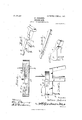
- FIG. 1 represents a side elevation of a switch stand with this improved switch lock applied thereto.
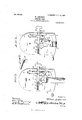
- Fig. 2 represents a top plan view of the lock casing with the top removed to show the working parts which are in position to lock the switch operating lever against movement.
- Fig. 3 represents a similar view with the working parts shown in the position which they assume when the switch lever is unlocked.
- Fig. i represents a longitudinal section taken on line 1-4 of Fig. 2.
- Fig. 5 represents a perspective view of the spring-pressed bolt detached.
- Fig. 6 represents a perspective view of the locking bar detached.
- Fig. 7 represents a perspective view of the locking plate detached.
- Fig. 8 represents a perspective view of the key used to unlock the switch operating lever.
- the numeral 10 designates a turn table or lock casing which is rotatably mounted on the upper side of a platform 1 by means of a shaft 2 to which it is fixed.
- the shaft 2 passes loosely through the platform 1 and is connected at its lower end with a lever for moving the switch points (not shown) and at its top is provided with the usual signal (not shown).
- the lock casing 10 is provided with suit ably shaped recesses in which are disposed the operating parts, and with adetachable top 11 having a recess or chamber 12 in which one end of a hand lever 35 pivoted to the casing is adapted to move.
- a locking bolt 13 is mounted to slide trans versely in a recess in the casing 10 and a coil spring 14 is disposed on its inner end on a guide pin 15, said spring bearing at one end against a shoulder 16 on the bolt and at its other end against the casing wall and resting 011 a supporting block 17 in the casing.
- This bolt is preferably of rectangular form and is provided at its outer end with a head 18 which lies on the outside of the casin across an opening in-the side thereof through which the bolt projects.
- One side of the bolt 13 has short spaced laterally projectin arms 19 and 20, the arm 19 having a slightdy concave inner face for a purpose to be described.
- This bolt also has a stepped notch 21. in its upper face for receiving a locking bar or latch 22.
- This bar 22 is pivoted at one end in a longitudinal recess formed near one side of the casing at right angles to the bolt recess and extends across the top of the bolt 13 and is provided near its free end with an aperture 23 through which projects a guide pin 24 secured to the bottom of the casing.
- a coil spring 25 is disposed on said pin 24 above the bar to hold said bar in engagement with the bolt notch 21.
- the bar or latch 22 preferably has the lower face of its free end beveled for a purpose hereinafter described, and one side thereof is notched to receive the step of the bolt 13.
- This bar also has a curved recess on its lower face to permit the ready insertion of the kcythercunder.
- a key chamber is formed beneath the free end of the locking bar or latch 22 and. has a key-hole 26 opening through the side wall of the casing through which a key 27 is passed to lift the bar 22 out of engagement with the bolt 13 and permit it to be pushed in to release the locking lever 35 as hereinafter described.
- a locking member 28 is pivotally mounted in a recess in the casing and has an arm 29 extending between the lateral arms 19 and 20 of-the bolt 13 and at its opposite side is provided with a segmental plate 30 Which is adapted to move in the path of the hand lever 35 and lock it in vertical position in engagement with the platform 1 and prevent the manipulating of the switch. From one side of this plate 30 projects an arm 31 having one side of its free end beveled to engage the side Wall of the casing which is preferably curved slightly to en age with said arm' whereby the segmental p ate 30 is held out of the path of the lever 35. When in this position the beveled side of the arm 29 bears against the concave face of the arm 19 and holds the bolt 13 retracted against the tension of its spring.
- the key 27 When it is desired to manipulate the switch the key 27 is inserted through the key-hole 26 and turned to raise the lock bar 22 out of engagement with the bolt 13 and the bolt is then pushed in until the beveled end of the arm 31 engages the side wall of the casing with the plate 30 out of the path of the lever 35.
- the lever 35 may then be moved into horizontal position the switch thrown in either direction and the lever again dropped into vertical position in engagement with the platform 1.
- the switchman has then only to push the bolt inward which causes the arm 31 to slip out of engagement with the casing wall and the spring pressed bolt pushes the arm 29 of the locking member outward and brings the plate 30 into the path of the lever 35 and the locking bar 22 drops into the notch 21 of the bolt when the parts are securely locked against movement until the key is again inserted.
- a switch lock comprising a casing, a segmental locking plate, a spring-pressed member bearing against one end of said locking plate, a lever pivoted to the casing and having one end engaged by one end of the locking .plate, a lock bar pivoted within the casing and adapted to engage the springpressed member to lock the same against movement, and a key to lift said lock bar to release said spring-pressed member and locking plate.
- a switch lock comprising a casing, a lever pivoted to said casing and having one end extending thereinto, a spring pressed bolt, 9. locking plate engaging said bolt and member and adapted to project into the path of said lever, a lock bar for holding said bolt in retracted position, and means to raise said bar to release said bolt to permit the locking member arm to be moved out of the path of the lever.
- a switch lock comprising a casing, a lever pivoted to said casing, a spring pressed bolt mounted to slide in said casing and having spaced laterally projecting arms and a notch in its upper face, a locking member mounted to turn in said casing and having an arm extending between said lateral arms and an arm adapted to project into the path of said lever, a lock bar pivoted at one end and adapted to fit in the notch in said bolt, and means for raising said'bar to release said bolt and permit the locking member to be moved out of the path of the lever.
- a switch lock comprising a casing, a lever pivoted to said casing, a bolt mounted to slide in said casing and having spaced laterally projecting arms and a notch in its upper face, a locking member mounted to turn in said casing and having an arm extending between said lateral bolt arms, a segmental plate carried by said member and adapted to extend into the path of said lever, an arm extending from said plate and having its free end beveled-to engage the side wall of the casing, means for locking said bolt against movement, and means for releasing said locking means.
Description
PATBNTED JUNE 11 1907.
W. ANDERSON. SWITCH LOOK. uruonrou FILED 93m. 24. 1000.
2 BHEBTS-SHEET 2.
awoewtoz WZW/am, 174 70077.
NN w\\\ I Yea aflozneaga' UNITED STATES PATENT orrron.
WILLIAM ANDERSON, OF MEMPHIS, TENNESSEE, ASSIGNOR OF FIVF- EIGHTHS TO A. A. STRANGE AND THREE EIGHTHS TO IN. 0. WHITE, OF MEMPHIS, TENNESSEE.
SWITCH-LOCK.
Specification of Letters Patent.
Patented June 11, 1907.
Application filed September 24,1906. Serial No. 335,942.
1'0 all whom "it TH/fIJ/ concern.-
Beit known that I, \VILLIAM ANDERSON, a citizen of the United States, residing at Memphis, in the county of Shelby and State of Tennessee, have invented certain new and useful Improvements in Switclidiocks; and I do declare the following to be a full, clear,
and exact description of the invention, such as will enable others skilled in the art to which it appertains to make and use the same.
This invention relates to an improved switch lock.
One object of the invention is to provide a switch lock of comparatively simple construction which will reliably hold the lever for moving the switch so that it cannot be moved except by the person who holds the key to the lock.
Another object is to provide a switch lock with a compound lever comprising two members, one of which is always locked against movement when the other is unlocked and vice versa.
In the accompanying drawings in which like reference characters are used to represent corresponding parts Figure 1 represents a side elevation of a switch stand with this improved switch lock applied thereto. Fig. 2 represents a top plan view of the lock casing with the top removed to show the working parts which are in position to lock the switch operating lever against movement. Fig. 3 represents a similar view with the working parts shown in the position which they assume when the switch lever is unlocked. Fig. i represents a longitudinal section taken on line 1-4 of Fig. 2. Fig. 5 represents a perspective view of the spring-pressed bolt detached. Fig. 6 represents a perspective view of the locking bar detached. Fig. 7 represents a perspective view of the locking plate detached. Fig. 8 represents a perspective view of the key used to unlock the switch operating lever.
Referring to the drawings for a more par ticular description of the invention the numeral 10 designates a turn table or lock casing which is rotatably mounted on the upper side of a platform 1 by means of a shaft 2 to which it is fixed. The shaft 2 passes loosely through the platform 1 and is connected at its lower end with a lever for moving the switch points (not shown) and at its top is provided with the usual signal (not shown).
The lock casing 10 is provided with suit ably shaped recesses in which are disposed the operating parts, and with adetachable top 11 having a recess or chamber 12 in which one end of a hand lever 35 pivoted to the casing is adapted to move.
A locking bolt 13 is mounted to slide trans versely in a recess in the casing 10 and a coil spring 14 is disposed on its inner end on a guide pin 15, said spring bearing at one end against a shoulder 16 on the bolt and at its other end against the casing wall and resting 011 a supporting block 17 in the casing. This bolt is preferably of rectangular form and is provided at its outer end with a head 18 which lies on the outside of the casin across an opening in-the side thereof through which the bolt projects. One side of the bolt 13 has short spaced laterally projectin arms 19 and 20, the arm 19 having a slightdy concave inner face for a purpose to be described. This bolt also has a stepped notch 21. in its upper face for receiving a locking bar or latch 22. This bar 22 is pivoted at one end in a longitudinal recess formed near one side of the casing at right angles to the bolt recess and extends across the top of the bolt 13 and is provided near its free end with an aperture 23 through which projects a guide pin 24 secured to the bottom of the casing. A coil spring 25 is disposed on said pin 24 above the bar to hold said bar in engagement with the bolt notch 21. The bar or latch 22 preferably has the lower face of its free end beveled for a purpose hereinafter described, and one side thereof is notched to receive the step of the bolt 13. This bar also has a curved recess on its lower face to permit the ready insertion of the kcythercunder.
A key chamber is formed beneath the free end of the locking bar or latch 22 and. has a key-hole 26 opening through the side wall of the casing through which a key 27 is passed to lift the bar 22 out of engagement with the bolt 13 and permit it to be pushed in to release the locking lever 35 as hereinafter described.
A locking member 28 is pivotally mounted in a recess in the casing and has an arm 29 extending between the lateral arms 19 and 20 of-the bolt 13 and at its opposite side is provided with a segmental plate 30 Which is adapted to move in the path of the hand lever 35 and lock it in vertical position in engagement with the platform 1 and prevent the manipulating of the switch. From one side of this plate 30 projects an arm 31 having one side of its free end beveled to engage the side Wall of the casing which is preferably curved slightly to en age with said arm' whereby the segmental p ate 30 is held out of the path of the lever 35. When in this position the beveled side of the arm 29 bears against the concave face of the arm 19 and holds the bolt 13 retracted against the tension of its spring.
When it is desired to manipulate the switch the key 27 is inserted through the key-hole 26 and turned to raise the lock bar 22 out of engagement with the bolt 13 and the bolt is then pushed in until the beveled end of the arm 31 engages the side wall of the casing with the plate 30 out of the path of the lever 35. The lever 35 may then be moved into horizontal position the switch thrown in either direction and the lever again dropped into vertical position in engagement with the platform 1. The switchman has then only to push the bolt inward which causes the arm 31 to slip out of engagement with the casing wall and the spring pressed bolt pushes the arm 29 of the locking member outward and brings the plate 30 into the path of the lever 35 and the locking bar 22 drops into the notch 21 of the bolt when the parts are securely locked against movement until the key is again inserted.
I claim as my invention- 1. A switch lock comprising a casing, a segmental locking plate, a spring-pressed member bearing against one end of said locking plate, a lever pivoted to the casing and having one end engaged by one end of the locking .plate, a lock bar pivoted within the casing and adapted to engage the springpressed member to lock the same against movement, and a key to lift said lock bar to release said spring-pressed member and locking plate.
2. A switch lock comprising a casing, a lever pivoted to said casing and having one end extending thereinto, a spring pressed bolt, 9. locking plate engaging said bolt and member and adapted to project into the path of said lever, a lock bar for holding said bolt in retracted position, and means to raise said bar to release said bolt to permit the locking member arm to be moved out of the path of the lever. I
4. A switch lock comprising a casing, a lever pivoted to said casing, a spring pressed bolt mounted to slide in said casing and having spaced laterally projecting arms and a notch in its upper face, a locking member mounted to turn in said casing and having an arm extending between said lateral arms and an arm adapted to project into the path of said lever, a lock bar pivoted at one end and adapted to fit in the notch in said bolt, and means for raising said'bar to release said bolt and permit the locking member to be moved out of the path of the lever.
5. A switch lock comprising a casing, a lever pivoted to said casing, a bolt mounted to slide in said casing and having spaced laterally projecting arms and a notch in its upper face, a locking member mounted to turn in said casing and having an arm extending between said lateral bolt arms, a segmental plate carried by said member and adapted to extend into the path of said lever, an arm extending from said plate and having its free end beveled-to engage the side wall of the casing, means for locking said bolt against movement, and means for releasing said locking means.
In testimony whereof I have hereunto set my hand in presence of two subscribing Witnesses.
WILLIAM ANDERSON.
Witnesses S. S. FALLS, l/VILL BOND.
Priority Applications (1)
| Application Number | Priority Date | Filing Date | Title |
|---|---|---|---|
| US33594206A US856437A (en) | 1906-09-24 | 1906-09-24 | Switch-lock. |
Applications Claiming Priority (1)
| Application Number | Priority Date | Filing Date | Title |
|---|---|---|---|
| US33594206A US856437A (en) | 1906-09-24 | 1906-09-24 | Switch-lock. |
Publications (1)
| Publication Number | Publication Date |
|---|---|
| US856437A true US856437A (en) | 1907-06-11 |
Family
ID=2924892
Family Applications (1)
| Application Number | Title | Priority Date | Filing Date |
|---|---|---|---|
| US33594206A Expired - Lifetime US856437A (en) | 1906-09-24 | 1906-09-24 | Switch-lock. |
Country Status (1)
| Country | Link |
|---|---|
| US (1) | US856437A (en) |
-
1906
- 1906-09-24 US US33594206A patent/US856437A/en not_active Expired - Lifetime
Similar Documents
| Publication | Publication Date | Title |
|---|---|---|
| US856437A (en) | Switch-lock. | |
| US880932A (en) | Padlock. | |
| US1000666A (en) | Handcuff and like lock. | |
| US297822A (en) | Ladder-hook | |
| US891129A (en) | Switch-lock. | |
| US1147175A (en) | Window-sash lock. | |
| US877747A (en) | Switch-stand. | |
| US524923A (en) | Umbrella-lock | |
| US1015908A (en) | Lock for mail-bags and the like. | |
| US313113A (en) | Double-acting lock | |
| US499459A (en) | Switch-lock | |
| US584985A (en) | Switch-lock | |
| US1003313A (en) | Milk-can lock. | |
| US846231A (en) | Lock. | |
| US1284002A (en) | Lock for switch-operating devices. | |
| US989093A (en) | Lock. | |
| US973920A (en) | Lock. | |
| US1205816A (en) | Coin-controlled mechanism. | |
| US1406790A (en) | Switch lock | |
| US991926A (en) | Switch-lock. | |
| US702028A (en) | Telephone-switchboard. | |
| US374269A (en) | William a | |
| US905777A (en) | Automatic switch-lock. | |
| US559467A (en) | Oscar stoddard | |
| US548222A (en) | Burton s |