US8564339B2 - Method and system for measuring amplitude and phase difference between two sinusoidal signals - Google Patents
Method and system for measuring amplitude and phase difference between two sinusoidal signals Download PDFInfo
- Publication number
- US8564339B2 US8564339B2 US13/587,418 US201213587418A US8564339B2 US 8564339 B2 US8564339 B2 US 8564339B2 US 201213587418 A US201213587418 A US 201213587418A US 8564339 B2 US8564339 B2 US 8564339B2
- Authority
- US
- United States
- Prior art keywords
- phase
- amplitude
- signal
- detector
- filter
- Prior art date
- Legal status (The legal status is an assumption and is not a legal conclusion. Google has not performed a legal analysis and makes no representation as to the accuracy of the status listed.)
- Expired - Fee Related
Links
Images


Classifications
-
- H—ELECTRICITY
- H03—ELECTRONIC CIRCUITRY
- H03L—AUTOMATIC CONTROL, STARTING, SYNCHRONISATION OR STABILISATION OF GENERATORS OF ELECTRONIC OSCILLATIONS OR PULSES
- H03L7/00—Automatic control of frequency or phase; Synchronisation
- H03L7/02—Automatic control of frequency or phase; Synchronisation using a frequency discriminator comprising a passive frequency-determining element
-
- G—PHYSICS
- G01—MEASURING; TESTING
- G01R—MEASURING ELECTRIC VARIABLES; MEASURING MAGNETIC VARIABLES
- G01R25/00—Arrangements for measuring phase angle between a voltage and a current or between voltages or currents
Definitions
- the present invention relates to measurement in the context of digital signal processing. More specifically, the present invention is concerned with a method and system for measuring amplitude and phase difference between two sinusoidal signals.
- phase detection The measurement of the phase between two sinusoidal signals, or phase detection, has a primary role in a number of signal processing applications.
- Phase-Locked Loop for example may be used in scanning-probe microscopy applications for example, such as Atomic-Force Microscopy, where the probe is a mechanical crystal or resonator which resonance characteristics change as it gets close to the scanned surface.
- a digital phase-locked loop as illustrated for example in FIG. 1 , is intended to drive a mechanical crystal or resonator 16 so that its transfer phase is constant, typically of about ⁇ 90 degrees at resonance.
- the PLL comprises a variable-frequency oscillator 12 and a phase detector 14 .
- the phase detector 14 It compares the phase of the input signal from the variable-frequency oscillator 12 with the phase of a signal from the mechanical crystal or resonator 16 and adjusts the frequency of the variable-frequency oscillator 12 to keep the phases matched.
- the signal from the phase detector 14 is used to control the variable-frequency oscillator 12 in a feedback loop.
- the phase detector 14 is based on a modulation followed by a low-pass filter operation, i.e. on synchronous demodulation.
- the role of the low-pass filter is to eliminate upper modulation products at twice the modulation frequency. As a result, the filter limits the useful frequency range of the PLL to at most one octave.
- the filter must be pre-adjusted according to the intended frequency range of the PLL, which affects both the precision and time response of the phase detector 14 . If the filter is wide the frequency range is large and the time response is short, but the precision is poor. Conversely, if the filter is narrow, the frequency range is also narrow, the precision is better, but the time response is poor. So, for a phase detector based on synchronous demodulation, the ratio of precision versus time-response of the phase detector is always tied to the intended frequency range of the PLL.
- phase detection uses phase detection.
- FIG. 1 is a circuit of a resonator and digital PLL, as known in the art
- FIG. 2 is a circuit of a phase/amplitude detector according to an embodiment of an aspect of the present invention
- FIG. 3 is a graph showing adaptation for a normalized least mean square filter according to an embodiment of an aspect of the present invention.
- FIG. 4 is a flowchart of a method according to an embodiment of an aspect of the present invention.
- a detector 20 according to an embodiment of an aspect of the present invention is illustrated in FIG. 2 , and will be described in an application such as PLL for illustrative purposes.
- the detector 20 compares the signal from a sine generator, such as a variable-frequency oscillator 12 with the output signal from a system, such as a resonator 16 , using an adaptive filter 22 .
- the sine generator 12 may be a sine/cosine generator of a recursive type (previously described in Fast and High-Precision Sine Generator for a TMS320C54x fixed-Point DSP Alex Boudreau, Bruno Paillard—Article published on the site of globaldsp.com.), for example, to provide a high-precision synthesis at a very low computational power.
- the adaptive filter 22 determines coefficients a and b that minimize a prediction error on a sample of the output signal from the system 16 , to estimate the output of the resonator 16 from a sample of the reference quadrature inputs Ref Sine, Ref Cosine.
- the coefficients a and b represent the transfer function of the system 16 at a current excitation frequency in the complex plane. From a measurement of the output signal of the system 16 excited by the sine generator 12 , the adaptive filter 22 uses the reference signal and an adaptive method to determine the coefficients a and b that minimize the prediction error on the sample of the output signal from the system 16 .
- the adaptive filter 22 may be a least mean square (LMS) filter for example (see “Adaptive Signal Processing”, Bernard Widrow, Samuel D. Stearns, Prentice Hall Signal Processing Series, ISBN 0-13-004029 01).
- LMS least mean square
- the adaptive filter 22 determines and tracks the coefficients a and b by the LMS method to predict the output signal of the system 16 with a minimized error in the least mean square sense. These coefficients are weights associated with the reference signal sin and cos.
- the sum of the weighed sin and cos signals allows generating a signal (Predic) to be compared with the output signal from the system 16 .
- the error between the signal (Predic) and the output signal from the system 16 is used in the adaptive method to optimize the two coefficients a and b for a following iteration.
- adaptive filter 22 Other adaptive method may be implemented by the adaptive filter 22 .
- the detector 20 can thus send a signal to control the sine generator 12 in the feedback loop.
- This detector and method are very efficient in terms of required computational power.
- the present phase/amplitude detector 20 does not require any pre- or post-filtering to eliminate modulation quadrature components. It can converge to a very high precision in a fixed, small number of samples, irrespective of the excitation frequency. As a result, when the excitation frequency is low, convergence can be achieved even in a small fraction of the period of the excitation signal.
- the present method yields a very high precision result in a fixed, small number of samples, irrespective of the signal frequency. As a result, when the frequency is low, amplitude measurement can be achieved even in a small fraction of an excitation period.
- the operating frequency range of the present phase/amplitude detector 20 extends from zero to the Nyquist frequency, i.e. half the sampling frequency, no over sampling is required. This allows using digital/analog converters running at lower frequencies but offering a better precision.
- the operating frequency range of a traditional, modulation-based, phase detector is generally a narrow-band, which extends over at most one octave to positively exclude modulation components at twice the excitation frequency.
- an F filter 18 may be used to take into account this transfer function (excluding the system under test), as shown in FIG. 2 .
- This loopback transfer function can thus be identified in broadband by the detector 20 in an initial phase. Once identified, this transfer function of the input-output analog chain is essentially a constant, and the present method includes the required correction for the analog chain, which is not possible with traditional methods.
- the adaptive filter 22 then performs a Filtered-X LMS.
- this analog-chain transfer function does not need to be identified, for instance in situations where only the relative phase around a point of operation needs to be determined. In that case, the a and b coefficients simply include the transfer function implicitly.
- the adaptation achieves an error equivalent to the precision of a typical 16-bits acquisition system in as few as 7 samples.
- this convergence rate is independent of the excitation frequency.
- the method also provides the amplitude information, using the same coefficient a and b (see relation 1 above). The convergence rate is the same.
- the method was started from a point where the error was completely unknown.
- a phase detector is used to track the variations of the phase from one sample to the next. In that case, the method is usually fast enough to keep the error at a very low-level at all times.
- phase detector according to an embodiment of the present invention was used in a PLL for applications in scanning-probe microscopy.
- the phase of a 32 kHz resonator could be measured with a 150 KHz sampling rate, rather than a sampling rate in the MHz as needed with traditional, modulation-based, phase detectors.
- the measurements were as fast as, and more accurate than, with traditional, modulation-based, phase detectors.
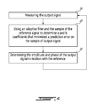
- FIG. 4 is a flowchart of a method according to an aspect of the invention.
- the method generally comprises measuring a sample of an output signal of a system excited by a sample of a reference signal (step 10 ); using an adaptive filter and the sample of the reference signal to determine a and b coefficients that minimize a prediction error on the sample of the output signal (step 20 ); determining at least one of: i) the amplitude and ii) phase of the output of the system using the relations (1) and (2) above (step 30 ); and repeating from step 10 .
- an input-output analog chain transfer function without the system may first be determined, depending on the application.
- the present system and method allow measuring accurately and very rapidly the phase, independently of the excitation frequency.
- phase detector may operate at lower sampling frequency than conventional phase detectors, slower and generally more accurate analog to digital converters may be used.
- the present detector and method allow adjusting the trade-off between time response and precision of the detection independently of the frequency range.
- the present detector and method may be used in different fields, such as, for example digital signal processing, digital radio, software-defined-radio, network analyzers, impedance analyzers, LRC-meters, phase-locked loops, harmonic synthesis . . . etc.
Landscapes
- Stabilization Of Oscillater, Synchronisation, Frequency Synthesizers (AREA)
Abstract
Description
Amplitude=(a 2 +b 2)0.5 (1)
Phase=Tan−1(b/a) (2)
Claims (17)
Amplitude=(a 2 +b 2)0.5 and
Phase=Tan−1(b/a).
Amplitude=(a 2 +b 2)0.5 and
Phase=Tan−1(b/a); and
Priority Applications (1)
| Application Number | Priority Date | Filing Date | Title |
|---|---|---|---|
| US13/587,418 US8564339B2 (en) | 2011-08-19 | 2012-08-16 | Method and system for measuring amplitude and phase difference between two sinusoidal signals |
Applications Claiming Priority (2)
| Application Number | Priority Date | Filing Date | Title |
|---|---|---|---|
| US201161525231P | 2011-08-19 | 2011-08-19 | |
| US13/587,418 US8564339B2 (en) | 2011-08-19 | 2012-08-16 | Method and system for measuring amplitude and phase difference between two sinusoidal signals |
Publications (2)
| Publication Number | Publication Date |
|---|---|
| US20130043907A1 US20130043907A1 (en) | 2013-02-21 |
| US8564339B2 true US8564339B2 (en) | 2013-10-22 |
Family
ID=47712226
Family Applications (1)
| Application Number | Title | Priority Date | Filing Date |
|---|---|---|---|
| US13/587,418 Expired - Fee Related US8564339B2 (en) | 2011-08-19 | 2012-08-16 | Method and system for measuring amplitude and phase difference between two sinusoidal signals |
Country Status (2)
| Country | Link |
|---|---|
| US (1) | US8564339B2 (en) |
| CA (1) | CA2787916A1 (en) |
Families Citing this family (2)
| Publication number | Priority date | Publication date | Assignee | Title |
|---|---|---|---|---|
| JP5975534B2 (en) * | 2011-09-26 | 2016-08-23 | 国立大学法人秋田大学 | Apparatus and method for measuring magnetic profile of DC magnetic field |
| US9780945B1 (en) * | 2016-04-01 | 2017-10-03 | Intel IP Corporation | Methods and devices for spur cancellation in digital phase locked loops |
Citations (8)
| Publication number | Priority date | Publication date | Assignee | Title |
|---|---|---|---|---|
| US6442273B1 (en) * | 1997-09-16 | 2002-08-27 | Sanyo Electric Co., Ltd. | Echo canceller and echo cancelling method |
| US6696886B1 (en) * | 2002-11-18 | 2004-02-24 | Industrial Technology Research Institute | Automatically adjusting gain/bandwidth loop filter |
| US20040181335A1 (en) * | 2003-03-14 | 2004-09-16 | Samsung Electronics Co., Ltd. | Apparatus for detecting location of movable body in navigation system and method thereof |
| US20100104148A1 (en) * | 2008-04-30 | 2010-04-29 | Board Of Regents, The University Of Texas System | Method and apparatus for detecting spiculated masses in mammography |
| US20110134984A1 (en) * | 2009-12-03 | 2011-06-09 | Canon Kabushiki Kaisha | Apparatus and method for obtaining phase corresponding to object position |
| US20120161834A1 (en) * | 2010-12-23 | 2012-06-28 | Electronics And Telecommunication Research Institute | Digital phase locked loop having insensitive jitter characteristic for operating circumstances |
| US8254589B2 (en) * | 2005-04-27 | 2012-08-28 | Asahi Group Holdings, Ltd. | Active noise suppressor |
| US20120280729A1 (en) * | 2009-12-17 | 2012-11-08 | August Nathaniel J | Adaptive digital phase locked loop |
-
2012
- 2012-08-16 US US13/587,418 patent/US8564339B2/en not_active Expired - Fee Related
- 2012-08-17 CA CA2787916A patent/CA2787916A1/en not_active Abandoned
Patent Citations (8)
| Publication number | Priority date | Publication date | Assignee | Title |
|---|---|---|---|---|
| US6442273B1 (en) * | 1997-09-16 | 2002-08-27 | Sanyo Electric Co., Ltd. | Echo canceller and echo cancelling method |
| US6696886B1 (en) * | 2002-11-18 | 2004-02-24 | Industrial Technology Research Institute | Automatically adjusting gain/bandwidth loop filter |
| US20040181335A1 (en) * | 2003-03-14 | 2004-09-16 | Samsung Electronics Co., Ltd. | Apparatus for detecting location of movable body in navigation system and method thereof |
| US8254589B2 (en) * | 2005-04-27 | 2012-08-28 | Asahi Group Holdings, Ltd. | Active noise suppressor |
| US20100104148A1 (en) * | 2008-04-30 | 2010-04-29 | Board Of Regents, The University Of Texas System | Method and apparatus for detecting spiculated masses in mammography |
| US20110134984A1 (en) * | 2009-12-03 | 2011-06-09 | Canon Kabushiki Kaisha | Apparatus and method for obtaining phase corresponding to object position |
| US20120280729A1 (en) * | 2009-12-17 | 2012-11-08 | August Nathaniel J | Adaptive digital phase locked loop |
| US20120161834A1 (en) * | 2010-12-23 | 2012-06-28 | Electronics And Telecommunication Research Institute | Digital phase locked loop having insensitive jitter characteristic for operating circumstances |
Non-Patent Citations (1)
| Title |
|---|
| Widrow, B. and Stearns, Samuel D.; Adaptive Signal Processing; Prentice-Hall Signal Processing Series, ISBN 0-13-004029 0. |
Also Published As
| Publication number | Publication date |
|---|---|
| CA2787916A1 (en) | 2013-02-19 |
| US20130043907A1 (en) | 2013-02-21 |
Similar Documents
| Publication | Publication Date | Title |
|---|---|---|
| Wang et al. | Noncontact distance and amplitude-independent vibration measurement based on an extended DACM algorithm | |
| CN113446925B (en) | Digital Phase Tracking Filters for Position Sensing | |
| Liang et al. | Fundamental limits on the digital phase measurement method based on cross-correlation analysis | |
| Cárdenas-Olaya et al. | Noise characterization of analog to digital converters for amplitude and phase noise measurements | |
| Ferrari et al. | Improving the accuracy and operating range of quartz microbalance sensors by a purposely designed oscillator circuit | |
| US8564339B2 (en) | Method and system for measuring amplitude and phase difference between two sinusoidal signals | |
| CN110720183B (en) | Optical frequency comb locking system, method for locking an optical frequency comb, and at least one machine readable medium | |
| JPWO2014155983A1 (en) | Signal detection circuit and scanning probe microscope | |
| Addabbo et al. | A novel front-end circuit for the digital conversion of QCM-D responses for FPGA-based frequency measurements | |
| Bertotti et al. | A simple method to measure phase difference between sinusoidal signals | |
| Jain et al. | Digital lock-in amplifier for space rubidium atomic clock | |
| Hu et al. | A compact wideband precision impedance measurement system based on digital auto-balancing bridge | |
| Yamada et al. | Demonstration of Johnson noise thermometry with all-superconducting quantum voltage noise source | |
| Singh | Simultaneous estimation of moving-vibration parameters by sliding Goertzel algorithm in PLL technique | |
| CN108333407B (en) | Wide-frequency-range analog-digital mixed self-balancing bridge | |
| Tyagi et al. | Frequency estimation techniques in capacitance-to-frequency conversion measurement | |
| Tyagi et al. | Frequency estimation based on moving-window DFT with fractional bin-index for capacitance measurement | |
| JPS63100381A (en) | Phase detector | |
| Sell et al. | A digital PLL circuit for resonator sensors | |
| CN107576842A (en) | A kind of broadband synchronous sampling method | |
| Zhao et al. | High accuracy amplitude and phase measurements based on a double heterodyne architecture | |
| Dabóczi | ADC testing using a resonator-based observer: Processing very long time records and/or testing systems with limited stability | |
| Das et al. | Noniterative digital AC bridge balance | |
| Senturk et al. | A quartz crystal microbalance (QCM)-based easy setup device for real-time mass change detection under high-power RF plasma | |
| US12235137B2 (en) | Position detection by an inductive position sensor |
Legal Events
| Date | Code | Title | Description |
|---|---|---|---|
| AS | Assignment |
Owner name: SOFT DB INC., CANADA Free format text: NUNC PRO TUNC ASSIGNMENT;ASSIGNORS:PAILLARD, BRUNO;BOUDREAU, ALEX;REEL/FRAME:028799/0093 Effective date: 20120814 |
|
| STCF | Information on status: patent grant |
Free format text: PATENTED CASE |
|
| FEPP | Fee payment procedure |
Free format text: PAYOR NUMBER ASSIGNED (ORIGINAL EVENT CODE: ASPN); ENTITY STATUS OF PATENT OWNER: SMALL ENTITY |
|
| FPAY | Fee payment |
Year of fee payment: 4 |
|
| FEPP | Fee payment procedure |
Free format text: MAINTENANCE FEE REMINDER MAILED (ORIGINAL EVENT CODE: REM.); ENTITY STATUS OF PATENT OWNER: SMALL ENTITY |
|
| LAPS | Lapse for failure to pay maintenance fees |
Free format text: PATENT EXPIRED FOR FAILURE TO PAY MAINTENANCE FEES (ORIGINAL EVENT CODE: EXP.); ENTITY STATUS OF PATENT OWNER: SMALL ENTITY |
|
| STCH | Information on status: patent discontinuation |
Free format text: PATENT EXPIRED DUE TO NONPAYMENT OF MAINTENANCE FEES UNDER 37 CFR 1.362 |
|
| FP | Lapsed due to failure to pay maintenance fee |
Effective date: 20211022 |