US856429A - Commutator-brush. - Google Patents
Commutator-brush. Download PDFInfo
- Publication number
- US856429A US856429A US23953705A US1905239537A US856429A US 856429 A US856429 A US 856429A US 23953705 A US23953705 A US 23953705A US 1905239537 A US1905239537 A US 1905239537A US 856429 A US856429 A US 856429A
- Authority
- US
- United States
- Prior art keywords
- brush
- hole
- shunt
- conductor
- web
- Prior art date
- Legal status (The legal status is an assumption and is not a legal conclusion. Google has not performed a legal analysis and makes no representation as to the accuracy of the status listed.)
- Expired - Lifetime
Links
Images
Classifications
-
- H—ELECTRICITY
- H01—ELECTRIC ELEMENTS
- H01R—ELECTRICALLY-CONDUCTIVE CONNECTIONS; STRUCTURAL ASSOCIATIONS OF A PLURALITY OF MUTUALLY-INSULATED ELECTRICAL CONNECTING ELEMENTS; COUPLING DEVICES; CURRENT COLLECTORS
- H01R39/00—Rotary current collectors, distributors or interrupters
- H01R39/02—Details for dynamo electric machines
- H01R39/36—Connections of cable or wire to brush
Definitions
- Ta'otZZ whom it may concern:
- M ylnvention relates to carbon .commutator brushes for electrical machines, and its obj ect is to provide improved rneansvfor connectingv flexible metal conductors to such brushes.
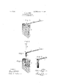
- FIG. 2, 3 and 4 arekviews, in perspective, respectively of a .hole 1n its outer end and a dou le-Web, Woven pin,'a shunt conductor and 'a brush which illustrate the structural 'details of my invention, a portion of the brush of Fig. 4 being broken away for. the sake of clearness of illustration, Fig. 5 is an enlarged, detail 2 5- in FigzS. yA hole 1 is bored into one' end of a brush 2, the upper portion of the hole being countersunk, asshown at 3, and notched, as shown at 4.
- Conducting shunt 5 comprises a double web thatis woven from wires or strands and a clip 6 which is soldered or otherwise secured to the free end of the shunt, by means of which connection may be made to other conducting portions of a br'ush holder, (not shown);
- the other end 7 of the conducting ⁇ shunt 5 is distended to tubular form and is bent approximately at right-angles to the main, attened portion and inserted into the hole l in the ⁇ brush 2.
- the strands on the one side of the tribular portion of the shunt 5 are spread at 8 -and a pin 9 is inserted and forced into the distended end 7, thereby causing good 'electrical contact between the i the pressure exerted by the pin 9.
- FIG. 1 is a perspective view of a brush* with its shunt oonnectlon made 1n accord view of one endlof the shunt conductor shownv j point of insertion.
- a carbon brush having a cylindrical hole in its outer end and a double-web,woven conductor, one 'endof which is inserted in said hole, and a pin that is driven into the hole through one side ofthe web and through the interior of the portion that is beyond the y5.
- a carbon brush havin outer end and a double-we iiexible' con ⁇ ductor, one end of which projects into said hole at an angle to its body portion, and a pin that projects through one side of the Web Patented Jua@ 11, ieo' ⁇ a hole in its f adjacent to the end of the brush and distende o the web within the hole.
- a contact lneinber having a cavity formed therein, a double-web, iiexible conductor, one end of which is inserted into Said cavity and a wedge that projects throu h one side of the flexible conductor into t cavity and forces the conductor into close contact with the walls thereof.
Landscapes
- Massaging Devices (AREA)
Description
PTENTED JUNE ll, 1%?.
WLMUTTR BRUSH APELIGATIGN FILED JAN.3,1905.
S LL S S E N W W vIO ' STATES PATENT FFE. ROBERT siEeRRiitD, oF PITTSBURG, PENN-sYLvANiA, AssieNoR To vvnsr- INGHOUSE,ELECTRIC-AMANURAOTURING COMPANY, A CORPORATION or rENNsYLvANIA.1
'coMmuTATon-Bnusl-i.
` Appnmion mammary 3,1905. sal-19.1 No. zeste?.
Ta'otZZ whom it may concern:
Be it known that I, ROBERT SIEGFRIE1 a citizen of the 'United States, and a' resident of Pittsburg,in the county of 'Allegheny and and State oflennsylvania, have invented a new and useful Improvement in'Cornrnutator-Brushes, ofvwhich the .following is a speci-lv fication. l
M ylnvention relates to carbon .commutator brushes for electrical machines, and its obj ect is to provide improved rneansvfor connectingv flexible metal conductors to such brushes.
panying drawing, in which ance with my invention. Figs. 2, 3 and 4 arekviews, in perspective, respectively of a .hole 1n its outer end and a dou le-Web, Woven pin,'a shunt conductor and 'a brush which illustrate the structural 'details of my invention, a portion of the brush of Fig. 4 being broken away for. the sake of clearness of illustration, Fig. 5 is an enlarged, detail 2 5- in FigzS. yA hole 1 is bored into one' end of a brush 2, the upper portion of the hole being countersunk, asshown at 3, and notched, as shown at 4. Conducting shunt 5 comprises a double web thatis woven from wires or strands and a clip 6 which is soldered or otherwise secured to the free end of the shunt, by means of which connection may be made to other conducting portions of a br'ush holder, (not shown); The other end 7 of the conducting` shunt 5 is distended to tubular form and is bent approximately at right-angles to the main, attened portion and inserted into the hole l in the` brush 2. The strands on the one side of the tribular portion of the shunt 5 are spread at 8 -and a pin 9 is inserted and forced into the distended end 7, thereby causing good 'electrical contact between the i the pressure exerted by the pin 9. The head sures a good electrical connectionbetween' My invention is illustratedin the acconc-v Figure 1 is a perspective view of a brush* with its shunt oonnectlon made 1n accord view of one endlof the shunt conductor shownv j point of insertion.
brush l and the conducting shunt, owing to- The construction shown and described inl lthe -shunt conductor and the top of the carn bon brush and one thatis readily and inoxpensively made meuch manner as to econornize space and insure a desired relation .of
the parts.
\ I claim as Iny invention:
l. The combination with a vbrush oir-ter` minalwhichris provided with 'a hole,of a double-web conducting cable havingcne end inserted into said hole and 'a pi'nwhich pierces one side of the cable and is forced into said. hole so as to distend the end of thecable.
2. The combination with a brush which is provided with a'hole, ofr ailattened, doubleweb conducting cable having one end inserted into said hole, and a pin which pierces one sideeof the cable and forces the, cable into close contact with the walls oi' the hole.
3. vA carbon Ubrush havin@r a cylindrical conductor, one end of which projects into said hole at an angle to its body portion,and a pin that projectsinto the bent end'of the woven conductor to clani'p itin position. A
4. A carbon brush having a cylindrical hole in its outer end and a double-web,woven conductor, one 'endof which is inserted in said hole, and a pin that is driven into the hole through one side ofthe web and through the interior of the portion that is beyond the y5. A carbon brush havin outer end and a double-we iiexible' con` ductor, one end of which projects into said hole at an angle to its body portion, and a pin that projects through one side of the Web Patented Jua@ 11, ieo'` a hole in its f adjacent to the end of the brush and distende o the web within the hole. o
6. A contact lneinber having a cavity formed therein, a double-web, iiexible conductor, one end of which is inserted into Said cavity and a wedge that projects throu h one side of the flexible conductor into t cavity and forces the conductor into close contact with the walls thereof.
In'testiniony whereof, l have hereunto subscribed my naine this 30th day of December, i904.
' ROBERT SIEGFRIED.
Witnesses: v
OTTO S. SOHAIRRR, BIRNEY HINEs.
Priority Applications (1)
| Application Number | Priority Date | Filing Date | Title |
|---|---|---|---|
| US23953705A US856429A (en) | 1905-01-03 | 1905-01-03 | Commutator-brush. |
Applications Claiming Priority (1)
| Application Number | Priority Date | Filing Date | Title |
|---|---|---|---|
| US23953705A US856429A (en) | 1905-01-03 | 1905-01-03 | Commutator-brush. |
Publications (1)
| Publication Number | Publication Date |
|---|---|
| US856429A true US856429A (en) | 1907-06-11 |
Family
ID=2924884
Family Applications (1)
| Application Number | Title | Priority Date | Filing Date |
|---|---|---|---|
| US23953705A Expired - Lifetime US856429A (en) | 1905-01-03 | 1905-01-03 | Commutator-brush. |
Country Status (1)
| Country | Link |
|---|---|
| US (1) | US856429A (en) |
Cited By (1)
| Publication number | Priority date | Publication date | Assignee | Title |
|---|---|---|---|---|
| US2523797A (en) * | 1945-12-13 | 1950-09-26 | Allied Electric Products Inc | Solderless wire terminal |
-
1905
- 1905-01-03 US US23953705A patent/US856429A/en not_active Expired - Lifetime
Cited By (1)
| Publication number | Priority date | Publication date | Assignee | Title |
|---|---|---|---|---|
| US2523797A (en) * | 1945-12-13 | 1950-09-26 | Allied Electric Products Inc | Solderless wire terminal |
Similar Documents
| Publication | Publication Date | Title |
|---|---|---|
| US856429A (en) | Commutator-brush. | |
| US886262A (en) | Switch-cord plug. | |
| US1247656A (en) | Terminal for conductors. | |
| US1342819A (en) | Connector-plug | |
| US902235A (en) | Cable-tip. | |
| US533910A (en) | Tip for electric conductors | |
| US661669A (en) | Connecting conductors to carbon brushes. | |
| US1145338A (en) | Spring-jack. | |
| US973592A (en) | Soldering-iron. | |
| US1696583A (en) | Coupling for electric circuits | |
| US294851A (en) | And frank shaw | |
| US1273647A (en) | Brush-holder. | |
| US1425632A (en) | Commutator brush | |
| US969796A (en) | Brush for dynamo-electric machines. | |
| US805249A (en) | Electric conductor. | |
| US938604A (en) | Brush for dynamo-electric machines. | |
| US845740A (en) | Commutator-brush for dynamo-electric machines. | |
| US1300239A (en) | Commutator-brush. | |
| US1167962A (en) | Cable-splice. | |
| US903972A (en) | Pigtail-brush. | |
| US631970A (en) | Electric terminal. | |
| US1510247A (en) | Electric-socket plug | |
| US561424A (en) | Paul minnis | |
| US761565A (en) | Trolley mechanism. | |
| DE1613433B2 (en) | BRUSH HOLDER OF AN ELECTRIC MOTOR, ESPECIALLY A SMALL MOTOR |