US856426A - Elastic-fluid turbine. - Google Patents
Elastic-fluid turbine. Download PDFInfo
- Publication number
- US856426A US856426A US29290205A US1905292902A US856426A US 856426 A US856426 A US 856426A US 29290205 A US29290205 A US 29290205A US 1905292902 A US1905292902 A US 1905292902A US 856426 A US856426 A US 856426A
- Authority
- US
- United States
- Prior art keywords
- stage
- fluid
- turbine
- elastic
- steam
- Prior art date
- Legal status (The legal status is an assumption and is not a legal conclusion. Google has not performed a legal analysis and makes no representation as to the accuracy of the status listed.)
- Expired - Lifetime
Links
- 239000012530 fluid Substances 0.000 title description 15
- XLYOFNOQVPJJNP-UHFFFAOYSA-N water Substances O XLYOFNOQVPJJNP-UHFFFAOYSA-N 0.000 description 4
- 239000007788 liquid Substances 0.000 description 2
- 238000005192 partition Methods 0.000 description 2
- 101100065720 Caenorhabditis elegans ets-5 gene Proteins 0.000 description 1
- 235000008694 Humulus lupulus Nutrition 0.000 description 1
- 244000025221 Humulus lupulus Species 0.000 description 1
- 238000006811 Samuelson reaction Methods 0.000 description 1
- 241001080526 Vertica Species 0.000 description 1
- 239000004927 clay Substances 0.000 description 1
- 238000007599 discharging Methods 0.000 description 1
- 238000000034 method Methods 0.000 description 1
Images
Classifications
-
- F—MECHANICAL ENGINEERING; LIGHTING; HEATING; WEAPONS; BLASTING
- F01—MACHINES OR ENGINES IN GENERAL; ENGINE PLANTS IN GENERAL; STEAM ENGINES
- F01D—NON-POSITIVE DISPLACEMENT MACHINES OR ENGINES, e.g. STEAM TURBINES
- F01D25/00—Component parts, details, or accessories, not provided for in, or of interest apart from, other groups
- F01D25/32—Collecting of condensation water; Drainage ; Removing solid particles
Definitions
- This invention relates to steam turbines and has for its object to provide simple and efficient means for separating moisture from the steam in its passagethrough a turbine of the multi-stage type, thereby preventing the loss inefficiency arising from the presence of moisture in the steam during its passage through the turbine.
- Iihe' turbine illustrated is a two-stage machine and the steam. is delivered into each of the stages througlinezzles 6, which may be e anding or non-expanding in characters he nozzles of the second stage are secured on the underside of a dis hragm iseparating centrifugal force .and collects in an annular the first from the seconc stage.
- diaphragm 7 On the upper side of diaphragm 7 is secured an inclined annularpartition S which overhangs the dis-j tributing nozzles 6 of the second stage and extends -for some distance toward the axis of the turbine, so that the steam as it is discharged from the first wheel is caused to flow radially inward toward the turbine shaft and thenl'outward under the partitions 8 to the pozzles of the second stage.
- Any moisture in the steam instead;of gassing radially inward with'the steam is t own outward by de'ression-ior channel 9 formed at the' perip hery of" the diaphragm 7.
- a plura ' employed to direct thesteam' in any prefer to provide drainage-channels 10 some or all of which may be fitted with stop-cocks 11.
- These channels discharge the water into an annular chamber 12 the water passes through passages 13 on to the diaphragm of the second stage.
- a condenser 16 Mounted in the base of the turbine is a condenser 16. and between the condenser tubes and the last wheel is awall or dia- 'hragm l7 slanting toward the shaft and oYming a part of the condenser casing.- It is provided with suitable openings, shown in dotted lines, to enable the steam-topass to the condenser tubes. This wall may also be desired manner through the condenser.
- e astic-iizid turbine of the mutistage type having means for preventing moisture from passing with the fluid from one stage to the next comprising an annular inclined partition overhanging the inlet nozzles of a stage so that the fluid has to pass inward toward the axis of the turbine and then outward to the nozzles, the liquid being thrown outward While the elastic fluid is passing inward, substantially as described.
Description
PATENTBD JUNE 11, 1907.
F. SAMUELSON.
ELASTIC FLUID TURBINE.
APPLICATION I'ILED 1320.22, 1905.
. WiTNESSES.
INVE NTDR.
FREdERlEK5AMUELSEIN UNITED STATES PATENT OFFICE. FREDERICK SAMUELSONLOF' RUGBY, ENGLAND, ASSIGNOR TO GENERAL ELECTRIC COMPANY, A CORPORATION OF NEW YORK.
. ELASTlC-FLUID TURBINEL Specification of Letters Patent.
Patented June 11,1907.
' Application filed December 22,1906. Serial No. 292,902-
To all whom, it may concern: Be it known that I, FREDERICK SAMUEL- SON, a subject-of the King of Sweden, residing at Rugby, En land,'have invented certain new and usefdl Improvements in -.Elastic- Fluid Turbines, of which the following is a specification.
This invention relates to steam turbines and has for its object to provide simple and efficient means for separating moisture from the steam in its passagethrough a turbine of the multi-stage type, thereby preventing the loss inefficiency arising from the presence of moisture in the steam during its passage through the turbine.
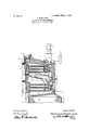
. The accompanying drawing which is a art.
sectional view of a multi-stage turbine o the Curtis type, clearly illustrates one method of carrymgm inventioninto eifect.
In the a'wing 1 re resents the turbine casing, 2 the shaft ant 3 the rotating elemerits or ,wheelscarrying the fluid receiving vanes or buckets 4 on their peripheries. Each of the wheels 8-,is shown as provided with three rows of buckets and inter osed between these rows. are-stationary buc ets 5 secured to the cas' 1. y
Iihe' turbine illustrated is a two-stage machine and the steam. is delivered into each of the stages througlinezzles 6, which may be e anding or non-expanding in characters he nozzles of the second stage are secured on the underside of a dis hragm iseparating centrifugal force .and collects in an annular the first from the seconc stage. On the upper side of diaphragm 7 is secured an inclined annularpartition S which overhangs the dis-j tributing nozzles 6 of the second stage and extends -for some distance toward the axis of the turbine, so that the steam as it is discharged from the first wheel is caused to flow radially inward toward the turbine shaft and thenl'outward under the partitions 8 to the pozzles of the second stage. Any moisture in the steam instead;of gassing radially inward with'the steam is t own outward by de'ression-ior channel 9 formed at the' perip hery of" the diaphragm 7. By thus de fleeting the steam in its passage between sta es themoisture is effectively separated and the: steam is delivered to. thesucceedingeta sin a dry condition.
be water which collects in the channel 9 may be discharged from'the turbine but I my invention a plura 'employed to direct thesteam' in any prefer to provide drainage-channels 10 some or all of which may be fitted with stop-cocks 11. These channels discharge the water into an annular chamber 12 the water passes through passages 13 on to the diaphragm of the second stage. Some of the water which isthus drained off from the first to the second stage is caused to evaporate owing. to the lower pressure and the steam so roduced does useful work in passing througi the remaining stages of the turbine.
Steam or other elastic fluid is admitted by the chest 14 containing one ormore admission valves. C In the resentillustration of iity of valves are employed, each under the control of an electromagnet 15. J
Mounted in the base of the turbine is a condenser 16. and between the condenser tubes and the last wheel is awall or dia- 'hragm l7 slanting toward the shaft and oYming a part of the condenser casing.- It is provided with suitable openings, shown in dotted lines, to enable the steam-topass to the condenser tubes. This wall may also be desired manner through the condenser.
. Although I have particularly described my invention as applied to a two-stage tu-r- "bine of the Curtis type it will be obvious that it is equally applicable to turbines havin more than two stages and also to any vertica discharging devices, wheel buckets acted upon by the fluid from said devices, and an annular device which causes the fluid exhausting from one stage to flow inwardly toward the shaft to discharge moisture in so doing, and to flow outwardly to the fluid-- 'dis'chargin devices of a lower-pressure stage. 2. e astic-i luid turbine of the mutistage type: having means for preventing moisture from passing with the fluid from one stage to the next comprising an annular inclined partition overhanging the inlet nozzles of a stage so that the fluid has to pass inward toward the axis of the turbine and then outward to the nozzles, the liquid being thrown outward While the elastic fluid is passing inward, substantially as described.
3. In'an elastic-fluid turbine of the multistage type, the combination of inlet nozzles, an inclined annular plate overhanging the inlet nozzles between one stage and the next succeeding stage, an annular channel surrounding said plate, and passages leading from said annular channel to the succeeding stage, substantially as and for the purposes described. a
4. In an elastic-fluid turbine which is divided. into stages of expansion, fluiddischarging devices and wheel buckets for each stage, and a means for separating moisture from the fluid as it flows from one sta e'tb another, comprising a plate for suddenly changing the direction of flow, one or more passages receiving the liquid discharged "from the fluid and that flowing over the plate, and a means in a stage of lower pressure for collecting the liquidand dischar ing it at a point or points out of the norma path of the entering fluid.
In witness whereof, I have hereunto set my hand this 7th clay ofDeeember, 1905.
FREDERICK SAMUELSON. Vitnesses:
ERNEST HARKER, ETHEL M. WEBB.
Priority Applications (1)
| Application Number | Priority Date | Filing Date | Title |
|---|---|---|---|
| US29290205A US856426A (en) | 1905-12-22 | 1905-12-22 | Elastic-fluid turbine. |
Applications Claiming Priority (1)
| Application Number | Priority Date | Filing Date | Title |
|---|---|---|---|
| US29290205A US856426A (en) | 1905-12-22 | 1905-12-22 | Elastic-fluid turbine. |
Publications (1)
| Publication Number | Publication Date |
|---|---|
| US856426A true US856426A (en) | 1907-06-11 |
Family
ID=2924881
Family Applications (1)
| Application Number | Title | Priority Date | Filing Date |
|---|---|---|---|
| US29290205A Expired - Lifetime US856426A (en) | 1905-12-22 | 1905-12-22 | Elastic-fluid turbine. |
Country Status (1)
| Country | Link |
|---|---|
| US (1) | US856426A (en) |
-
1905
- 1905-12-22 US US29290205A patent/US856426A/en not_active Expired - Lifetime
Similar Documents
| Publication | Publication Date | Title |
|---|---|---|
| US3881842A (en) | Diaphragm for steam turbine stage | |
| US741776A (en) | Means for improving the efficiency of turbines. | |
| US856426A (en) | Elastic-fluid turbine. | |
| US2399009A (en) | Elastic fluid turbine | |
| US2377611A (en) | Turbine | |
| US1597467A (en) | Turbine blading | |
| US3724967A (en) | Moisture removal device for a steam turbine | |
| US1814629A (en) | Elastic fluid turbine | |
| US1004664A (en) | Condenser. | |
| US744727A (en) | Means for improving the efficiency of turbines. | |
| US1723110A (en) | Elastic-fluid turbine | |
| US910170A (en) | Elastic-fluid turbine. | |
| US791674A (en) | Elastic-fluid turbine. | |
| US1297803A (en) | Elastic-fluid turbine. | |
| US984435A (en) | Condenser. | |
| US860967A (en) | Elastic-fluid turbine. | |
| US1012813A (en) | Turbine. | |
| US777313A (en) | Steam-turbine. | |
| US1352438A (en) | Condenser | |
| US1277151A (en) | Condensate and air removing apparatus. | |
| US837308A (en) | Apparatus for condensing steam. | |
| US1171216A (en) | Steam-turbine. | |
| US753855A (en) | Expansible-fluid turbine. | |
| US1362963A (en) | Turbine | |
| US822257A (en) | Elastic-fluid turbine. |