US856418A - Automatic coupling for railway-vehicles. - Google Patents
Automatic coupling for railway-vehicles. Download PDFInfo
- Publication number
- US856418A US856418A US29594006A US1906295940A US856418A US 856418 A US856418 A US 856418A US 29594006 A US29594006 A US 29594006A US 1906295940 A US1906295940 A US 1906295940A US 856418 A US856418 A US 856418A
- Authority
- US
- United States
- Prior art keywords
- lever
- coupling
- vehicles
- railway
- draw
- Prior art date
- Legal status (The legal status is an assumption and is not a legal conclusion. Google has not performed a legal analysis and makes no representation as to the accuracy of the status listed.)
- Expired - Lifetime
Links
- 230000008878 coupling Effects 0.000 title description 23
- 238000010168 coupling process Methods 0.000 title description 23
- 238000005859 coupling reaction Methods 0.000 title description 23
- 238000005452 bending Methods 0.000 description 1
- 230000036461 convulsion Effects 0.000 description 1
Images
Classifications
-
- B—PERFORMING OPERATIONS; TRANSPORTING
- B61—RAILWAYS
- B61G—COUPLINGS; DRAUGHT AND BUFFING APPLIANCES
- B61G1/00—Couplings comprising interengaging parts of different shape or form and having links, bars, pins, shackles, or hooks as coupling means
- B61G1/02—Couplings comprising interengaging parts of different shape or form and having links, bars, pins, shackles, or hooks as coupling means having links or bars coupling or uncoupling by rotating around a transverse horizontal axis
- B61G1/06—Couplings comprising interengaging parts of different shape or form and having links, bars, pins, shackles, or hooks as coupling means having links or bars coupling or uncoupling by rotating around a transverse horizontal axis and coupling when the coupling halves are pushed together
Definitions
- This invention relates to automatic couplings for railway vehicles, and particularly to that class of coupling in which a weighted pivoted lever, according to its position at one or other'side of its dead center, maintains the parts of the coupling in the coupling or uncoupled position respectively, and is designed to obviate the necessity of independent means for securing the lever in either terminal position, to provide means for maintaining the coupling securely in both terminal positions, to avoid any possibility of jerks or jolts swinging or bending the weighted lever or shaking it out of position when set until it is released and to permit of the non automatic coupling and uncoupling of the vehicles if desired.
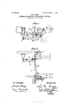
- Figure 1 is a side view showing the apparatus in the coupling position and in dotted lines in the uncoupled position.
- Fig. 2 is a plan of the apparatus in the coupling position.
- the weighted lever j which according to its position maintains the coupling hook a jointed to the draw hook in the coupling or uncoupled position is mounted on a horizontal pivot Z carried by a bracket under the frame of the wagon, and so arranged that the weight is above the pivot Z and not hanging below it as hitherto.
- the weighted lever j is connected by a link or connecting rod m with a lever or arm n keyed on the operating rod 6 mounted on the draw beam 0, in such a way that when the rod 1) is rotated into the coupling position the weight Ir is drawn or swung forward some distance in front of the dead point and toward the draw beam 0 thereby raising the coupling hook a and keeping it raised and so that when the operating rod 1) is turned into the uncoupled position the weight kis raised and swung backward to a short distance behind the dead point.
- the coupling hook a is lifted and lowered by means of a rod or link (Z connected to the lever e rigidly mounted upon the operating rod or shaft b.
- the pivot connecting the link (Z and lever 0 passes through a slot in the end of the lever (Z in which it is free to slide.
- the shaft b is mounted in bearings g preferably carried by the draw beam 0 and provided at one or both ends with a handle 71 for operating it and the bearings g are formed with stops f which engage corresponding proj ections or stops on the shaft 1) to restrict the movement of the shaft.
- the operation of the coupling is as fol lows :WVhen two vehicles are to be coupled the handles i at either end of the shafts b of the two couplings are raised from the dotted position shown in Fig. 1, to that shown in full lines when further rotation is stopped by the projections 7t on the handles "L engaging the stops f.
- the rotation of the shafts f) raises the levers e and with them the links (Z and coupling hooks a, and at the same time by means of the lever a and links m pulls over the levers and weights is till the resultant leverage of the weights 7r is considerably more than sufficient to permit them to counterbalance the weights of the hooks a.
Landscapes
- Engineering & Computer Science (AREA)
- Mechanical Engineering (AREA)
- Passenger Equipment (AREA)
Description
No 856,418. PATENTED JUNE 11, 1907. L. M. OROSZ.
AUTOMATIC COUPLING FOR RAILWAY VEHICLES.
APPLICATION FILED JAN.13, 1906 WITNESSES. INVENTOR 1 UNITED STATES PATENT ()EEIGE.
LUDWVIG MATIASZ OROSZ, OF ARAD, AUSTRIA-HUNGARY, ASSIGNOR OF ON F- HALF TO DANIEL NEUMAN, OF ARAD, AUSTRIA-HUNGARY.
AUTOMATIC COUPLING FOR RAILWAY-VEHICLES.
Specification of Letters Patent.
Patented June 11, 1907.
Application filed January 13, 1906. Serial No. 295,940.
To all whom it may concern:
Be it known that I, Lunwrc Miiritisz Onosz, a subject of the King of Hungary, and a resident in the city of Arad, in the Empire of Austria-Hungary, have invented certain new and useful Improvements in Automatic Couplings for Railway-Vehicles, of which the following is a specification.
This invention relates to automatic couplings for railway vehicles, and particularly to that class of coupling in which a weighted pivoted lever, according to its position at one or other'side of its dead center, maintains the parts of the coupling in the coupling or uncoupled position respectively, and is designed to obviate the necessity of independent means for securing the lever in either terminal position, to provide means for maintaining the coupling securely in both terminal positions, to avoid any possibility of jerks or jolts swinging or bending the weighted lever or shaking it out of position when set until it is released and to permit of the non automatic coupling and uncoupling of the vehicles if desired.
The accompanying drawings show one form of the invention.
Figure 1. is a side view showing the apparatus in the coupling position and in dotted lines in the uncoupled position. Fig. 2 is a plan of the apparatus in the coupling position.
The weighted lever j which according to its position maintains the coupling hook a jointed to the draw hook in the coupling or uncoupled position is mounted on a horizontal pivot Z carried by a bracket under the frame of the wagon, and so arranged that the weight is above the pivot Z and not hanging below it as hitherto. The weighted lever j is connected by a link or connecting rod m with a lever or arm n keyed on the operating rod 6 mounted on the draw beam 0, in such a way that when the rod 1) is rotated into the coupling position the weight Ir is drawn or swung forward some distance in front of the dead point and toward the draw beam 0 thereby raising the coupling hook a and keeping it raised and so that when the operating rod 1) is turned into the uncoupled position the weight kis raised and swung backward to a short distance behind the dead point.
The coupling hook a is lifted and lowered by means of a rod or link (Z connected to the lever e rigidly mounted upon the operating rod or shaft b. The pivot connecting the link (Z and lever 0 passes through a slot in the end of the lever (Z in which it is free to slide.
The shaft b is mounted in bearings g preferably carried by the draw beam 0 and provided at one or both ends with a handle 71 for operating it and the bearings g are formed with stops f which engage corresponding proj ections or stops on the shaft 1) to restrict the movement of the shaft.
The operation of the coupling is as fol lows :WVhen two vehicles are to be coupled the handles i at either end of the shafts b of the two couplings are raised from the dotted position shown in Fig. 1, to that shown in full lines when further rotation is stopped by the projections 7t on the handles "L engaging the stops f. The rotation of the shafts f) raises the levers e and with them the links (Z and coupling hooks a, and at the same time by means of the lever a and links m pulls over the levers and weights is till the resultant leverage of the weights 7r is considerably more than sufficient to permit them to counterbalance the weights of the hooks a. The vehicles are then run together and the slots in the ends of the levers d permit the extremities of each hook a to ride over the draw-bar of the other hook and enter into engagement therewith. WVhen the vehicles are to be uncoupled the shafts b of the two couplings are retated into the position shown in dotted lines in Fig. 1. by the handles i when further rotation is prevented by the projections 7L engag ing the lower stopsf of the bearings g. This rotation of the shafts b, by means of the levers n and links m raises the weights It and pushes them back a short distance beyond their dead centers and raises the connections between levers n and links m above the dead point so that the weights 7r cannot be jolted forward. At the same time the rotation of the shafts I) lowers and disengages the hooks a by means of the lovers 0 and links (Z and, due to the position of the weights 7t beyond the dead centers, the weight of the hooks a also acts to maintain the weights in position and to prevent them being jolted forward.
l Vhat I claim as my invention and desire to protect by Letters Patent isz 1. In a coupling .for railway and like vehicles the combination with the draw-beam, of an operating shaft a handle to rotate same, a weighted lever pivotedtofthewagon independently of the operating shaft, a lever on the operating shaft, a link connecting said lever and said Weighted lever, a draw-hook mounted on the draw beam, a second lever on the operating shaft a link connecting said second lever With the draw-hook and stops to restrict the rotation of the operating lever substantially as hereinbefore described.
2. In a coupling for railway and like vehicles the combination with the draWbeam, of an operating shaft, a handle to rotate same, a lever pivoted at its lower end to the frame of the Wagon, a Weight upon the upper end of said lever, a lever on the operating shaft, a link connecting said lever and said Weighted lever, and adapted on the rotation of the op erating shaft to move said Weighted lever from one side to the other 01' its dead center, a draw-hook mounted on the draw beam, a
second lever on the operating shaft a link 20 my name in the presence of two subscribing Witnesses.
LUDW IG MATIASZ OROSZ.
\Vitnesses:
JULIUS new, F. C. MALLETT
Priority Applications (1)
| Application Number | Priority Date | Filing Date | Title |
|---|---|---|---|
| US29594006A US856418A (en) | 1906-01-13 | 1906-01-13 | Automatic coupling for railway-vehicles. |
Applications Claiming Priority (1)
| Application Number | Priority Date | Filing Date | Title |
|---|---|---|---|
| US29594006A US856418A (en) | 1906-01-13 | 1906-01-13 | Automatic coupling for railway-vehicles. |
Publications (1)
| Publication Number | Publication Date |
|---|---|
| US856418A true US856418A (en) | 1907-06-11 |
Family
ID=2924873
Family Applications (1)
| Application Number | Title | Priority Date | Filing Date |
|---|---|---|---|
| US29594006A Expired - Lifetime US856418A (en) | 1906-01-13 | 1906-01-13 | Automatic coupling for railway-vehicles. |
Country Status (1)
| Country | Link |
|---|---|
| US (1) | US856418A (en) |
-
1906
- 1906-01-13 US US29594006A patent/US856418A/en not_active Expired - Lifetime
Similar Documents
| Publication | Publication Date | Title |
|---|---|---|
| US856418A (en) | Automatic coupling for railway-vehicles. | |
| US260725A (en) | Car-coupling | |
| US306065A (en) | darling | |
| US196267A (en) | Improvement in car-couplings | |
| US296640A (en) | Car-coupling | |
| US254111A (en) | chase | |
| US357504A (en) | Car-coupling | |
| US255547A (en) | Car-coupling attachment | |
| US220719A (en) | Improvement in car-couplings | |
| US267531A (en) | Car-coupling | |
| US342381A (en) | Car-coupling | |
| US499078A (en) | Cab coupling | |
| US300245A (en) | Thomas geeitt | |
| US353804A (en) | Oae coupling | |
| US567902A (en) | Car-coupling | |
| US490811A (en) | miller | |
| US150158A (en) | Improvement in car-couplings | |
| US474691A (en) | Car-coupling | |
| US449974A (en) | Car-coupling | |
| US368914A (en) | evans | |
| US211341A (en) | Improvement in car-couplings | |
| US483640A (en) | Car-coupling | |
| US267101A (en) | Car-coupling | |
| US305418A (en) | Car-coupling | |
| US185874A (en) | Improvement in car-couplings |