US856417A - Electrical controller for steam plants, &c. - Google Patents
Electrical controller for steam plants, &c. Download PDFInfo
- Publication number
- US856417A US856417A US1905251028A US856417A US 856417 A US856417 A US 856417A US 1905251028 A US1905251028 A US 1905251028A US 856417 A US856417 A US 856417A
- Authority
- US
- United States
- Prior art keywords
- contact
- motor
- stem
- lever
- valve
- Prior art date
- Legal status (The legal status is an assumption and is not a legal conclusion. Google has not performed a legal analysis and makes no representation as to the accuracy of the status listed.)
- Expired - Lifetime
Links
Images
Classifications
-
- G—PHYSICS
- G05—CONTROLLING; REGULATING
- G05D—SYSTEMS FOR CONTROLLING OR REGULATING NON-ELECTRIC VARIABLES
- G05D23/00—Control of temperature
- G05D23/19—Control of temperature characterised by the use of electric means
- G05D23/275—Control of temperature characterised by the use of electric means with sensing element expanding, contracting, or fusing in response to changes of temperature
- G05D23/27535—Details of the sensing element
- G05D23/2754—Details of the sensing element using bimetallic element
-
- Y—GENERAL TAGGING OF NEW TECHNOLOGICAL DEVELOPMENTS; GENERAL TAGGING OF CROSS-SECTIONAL TECHNOLOGIES SPANNING OVER SEVERAL SECTIONS OF THE IPC; TECHNICAL SUBJECTS COVERED BY FORMER USPC CROSS-REFERENCE ART COLLECTIONS [XRACs] AND DIGESTS
- Y10—TECHNICAL SUBJECTS COVERED BY FORMER USPC
- Y10T—TECHNICAL SUBJECTS COVERED BY FORMER US CLASSIFICATION
- Y10T137/00—Fluid handling
- Y10T137/1842—Ambient condition change responsive
- Y10T137/1939—Atmospheric
- Y10T137/1963—Temperature
Definitions
- My invention has for its object to provide an improved electrical controller, adapted for use as an automatic heat regulator, and
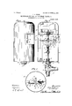
- Figure 1 is a view inside elevation, with some parts broken away, showing the improved automatic heat regulator.
- Fig. 2 is a vertical section taken approximately on the line 0s? of Fig. 1.
- Fig. 3 is a horizontal section taken through the device on the line m x of Fig.
- Fig. 4 is a detail in elevation, showing a reversing switch, and a spring kicker for moving the same.
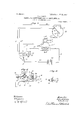
- Fig. 5 is a view in diagram, illustrating the wiring of the device, and Fig. 6 is a view of the revers ing switch with the parts turned upside down.
- the numeral 1 indicates one of the steam or water circulating pipes of a heating system, shown as having horizontal and verticalsections connected by a Tcoupling 2,-aifording a valve seat, and having at its upper end a plug 3. Circulation through the pipe 1 is adapted to be cut elf by a valve 4, the stem 5 of which works vertically upward through the plug 3 and through a stuiiing box 6,
- thevalve stem 5 has a supplemental section 5*, the upper end of which is threaded.
- Said sleeve 7 is'rigidly connected to the stem section 5 by a set screw 9, and a bushing 10 of insulating material is preferably placed is yielding'ly connected I around said stem Within said sleeve.
- the said sleeve 7 has a'detachable cap nut 8 that engages the headed upper end of the stem 5, as best shown in Fig. 2.
- the spring 3 reacts against the head of the stem 5 and against an insulating washer 11 which is placed against the end of the stem section 5.
- This frame 14 has a disk-like upper plate 15, a similar lo'wer plate 16, and an intermediate shelf or arm 17.
- the said plate 16 has ahub rigidly secured thereto by a set screw 13.
- An insulating bushing 19 is interposed between the plug 3 and the hub 16 for a purpose which will presently appear.
- the electric motor which, as shown, is directly supported by a bracket 21 mounted on the upper plate of the main supporting bracket 14. Of the parts of this motor, it is only necessary to particularly designate the commutator the brushes 20" the lield magnet 20" and the pole pieces 120 of said field magnet.
- the commutator 20 carries a spur pinion 22 that meshes with a spur gear 23.
- This spur gear 23 is rigidly, but detachably secured, as shown, by. a set screw 24. to a hub-like nut 25.
- This nut 25 works on the threaded end of the valve stem section 5, is loosely journaled inthe plate 15, and below said plate, is flanged so that it is held against endwise movement.
- the valve 4 may be raised and lowered, ac cording to the direction of movement of said gear.
- the direction ol rotation of said gear depends upon the direction of rotation of the motor armature.
- This switch lever has one contact finger 33 that is elec trically connected therewith, and it carries insulated therefrom by a spacing block 36 or suitable insulating material.
- the two fingers 34 and 35 are electrically connected with each other, preferably by being formed from The stem section 5* is held against rota- 10" that telescopes over the plug 3, and is The numeral 20 indicates a small reversible
- ICC two other contact fingers 34 and 35 that are IIO the same piece of metal, as shown in Fig. 6.
- These contact fingers, 33, 34 and 35, 006 erate with/tho four contact posts just note in a manner which will presently be described.
- One extreme position of the switch lever 32 and its fingers is illustrated in Fig. 2, and the other extreme position thereof is indicated in Fig. 4. To quickly move said switch lever from one extreme position to the other, at the proper times, and under the control or action of the valve stem 5 -5 a.
- This spring kicker involves an oscillatory bolt 37 which is pivoted to the bracket 14 at 38, and at its free end, has a telescopicallymovable head 39, the outer end of which is pronged and preferably carries a 1 small roller 40.
- a lever 42 is pivoted at its intermediate portion on the stud 31 before noted. At'its end, adjacent to the roller 40, the lever 42 is provided with an approximately straight surface with which'said roller engages, and this surface terminates in laterally spaced lugs 43. At its other end, said lever is provided with laterally spaced lugs 44 that act as tappets, to alternately engage a stud or projection 45 on said switch lever 32.
- the valve stem section 5 carries a pair or laterally projecting longitudinally spaced tappet lugs 46, located one on each side of the free end ofthe rod 37, 'andengageable alternately with the head 39.- The exact vrelatiofi of these parts just described will more fully appear in the description of the operation.
- a thin shell or housing 47 preferably formed of wood fiber, or other insulating inaterial, is detachably'secured to the-plates 15 and 16of the bracket 14, and incloses the parts of the apparatus so far described.
- thermostat For automatically closing and opening the circuits to the field and armature of the motor, under varyirfg temperatures, I thermostat.
- This thermostat may suitable form, such as a standard thermometer-haying a pointer which is arranged to be vibrated, usually over a dial, by thermally actuated devices, not necessary for the purposes of this case to consider.
- this thermostat or thermometer is indicated in diagram, the case being designated by the numeral 48 and the pointer thereof being designated by the numeral 49.
- the numergrovide a als 50 and 51 designate contacts applied to the face of the thermostat, one on each side of the free end of-the pointer 49, and in position to be engaged thereby: It may be assumed that the pointer 49 will engage the contact 50 under a low temperature, and will engage the contact 51 under a high temperature. The which is illustrated only in Fig.
- the numeral 52 indicates the battery, which is connected by a lead 53 to the stud 31 which afiords the lever pivot before described.
- the battery 52 is also connected to the binding ost 28 by a lead 54 that includes the coil 0 the motor field magnet 20.
- the bindin .post 29 is connected by a wire 55 to one o the commutator brushes 20 and the other commutator brush is connected by a wire 55 to the pointer 49 of the thermostat or thermometor.
- the contact post ,27 is'connected by a wire 56 to the contact 50 of the thermostat, While the contact post 30 is connected by a wire 57 to the contact 51 of said thermostat.
- the valve In Fig. 2, the valve must be assumed to be moving upward under the action of the motor, the armature of. which is then rotating in the direction indicated by the arrow marked through the lever 32. and finger 33 of the contact post .29, thence through the wire 55 to one contact brush 20', through thearmature 'of the motor thence out through the other brush and .the wire 55 to the pointer 49 of the thermostat, from thence through the wire 56 to the contact post 27, thence through the contact fingers 34 and 35 to the contact post 28, and from thence through the lead 54 and the coil of the field .magnet 20 back to the battery.
- switch lever 32 will not be moved until after said valve has been closed.
- the spring 8 permits a considerable downward movement of the supplemental valve stem 5 after the valve has been closed, and it also affords a cushion between the said parts which prevents the valve from being seated under excessive pressure.
- the insulations' at and 19 prevent grounding of the motor circuit.
- the insulating case 47 covers up all of the parts that are electrically charged when the' motor is in action.
- the current for operating themotor is, of course, supplied by the battery or source of energy 52'. 7
- a tensi n or friction bar 58 is secured at its ends to'the plate 26, and presses the upper surface of said lever, under friction.
- the device described while especially adapted for use as a heat regulator for hot water, steam and hot air heating systems, is capable of many other uses. For instance, it is well adapted for use as an automatic means for regulating the supply of steam to a pump used to elevate water, and in which a floatactuated circuit closer and breaker may be used in lieu ofthe thermostat.
- a reversible electric motor of a two part operating plunger, receiving reciprocating movements from said motor, the sections thereof being yieldingly connected, circuit connections to said motor involving a circuit-maker-and-breaker and a reversing switch, a tappet lever, operative on said switch, and a sprin actuated kicker arranged to be thrown om one side to the other of a dead center, by said operating lunger, and operating in turn on said tappet ever, substantially as described,
Description
PATENTED JUNE 11, 1907.
J. A. OLSON. ELECTRICAL CONTROLLER FOR STEAM PLANTS, &0.
APPLIOATION FILED MAR. 20, 1905.
r m 96.7 m a 2 M wifiases.
Nb. 856,417. PATENTED JUNE 11, 1907. q. A. OLSON. ELECTRICAL CONTROLLER FOR STEAM PLANTS, awn
APPLICATION FILED MAR. 20, 1905.
2 SHEETS-411E311? Z,
J j J7) J0 f Ff wz i ximsw. EJ627707.
Q? will? .6? 029027.
UNITED STATES PATENT OFFICE.
ELECTRICAL CONTROLLER FOR STEAM PLANTS, &c.
Specification of Letters Patent...
Patented June 11, 1907.
Application filed March 20, 1905. Serial No. 251,028.
To all whom it um/y concern:
Be it known that I, JOHN A. OLSON, a citi zen of the United States, residing at Minneapolis, in the county of llennepin and State of Minnesota, have invented certain new and usei'ul Improvements inflfllectric Controllers for Steam Plants, &c.; and I do hereby de clare the following to be a lull, clear, and exact description of the invention, such as will enable others skilled in the art to which it appertains to make and use the same.
My invention has for its object to provide an improved electrical controller, adapted for use as an automatic heat regulator, and
for other purposes, and to this end, it consists of the novel devices and combinations of devices hereinafter described and defined in the claims.
The invention applied to open and close a valve of a steam or hot water heating system, is illustrated in the accompanying drawings, wherein like characters indicate like parts throughout the several views.
Figure 1 is a view inside elevation, with some parts broken away, showing the improved automatic heat regulator. Fig. 2 is a vertical section taken approximately on the line 0s? of Fig. 1. Fig. 3 is a horizontal section taken through the device on the line m x of Fig. Fig. 4 is a detail in elevation, showing a reversing switch, and a spring kicker for moving the same. Fig. 5 is a view in diagram, illustrating the wiring of the device, and Fig. 6 is a view of the revers ing switch with the parts turned upside down.
' The numeral 1 indicates one of the steam or water circulating pipes of a heating system, shown as having horizontal and verticalsections connected by a Tcoupling 2,-aifording a valve seat, and having at its upper end a plug 3. Circulation through the pipe 1 is adapted to be cut elf by a valve 4, the stem 5 of which works vertically upward through the plug 3 and through a stuiiing box 6,
shown as applied to said plug. In this ap plication of the invention, thevalve stem 5, has a supplemental section 5*, the upper end of which is threaded.
For an important purpose, which will presently appear, the supplemental valve stem or extension 5 tg said stem 5, such connection being prefera 1y made by a sleeve 7, and a spring 8. Said sleeve 7is'rigidly connected to the stem section 5 by a set screw 9, and a bushing 10 of insulating material is preferably placed is yielding'ly connected I around said stem Within said sleeve. At its I lower end, the said sleeve 7 has a'detachable cap nut 8 that engages the headed upper end of the stem 5, as best shown in Fig. 2. The spring 3 reacts against the head of the stem 5 and against an insulating washer 11 which is placed against the end of the stem section 5. tion by a bracket 12 rigidly secured thereto, and working slidably on a vertical guide stud 13 supported by a frame 14. This frame 14 has a disk-like upper plate 15, a similar lo'wer plate 16, and an intermediate shelf or arm 17. The said plate 16 has ahub rigidly secured thereto by a set screw 13. An insulating bushing 19 is interposed between the plug 3 and the hub 16 for a purpose which will presently appear.
electric motor which, as shown, is directly supported by a bracket 21 mounted on the upper plate of the main supporting bracket 14. Of the parts of this motor, it is only necessary to particularly designate the commutator the brushes 20" the lield magnet 20" and the pole pieces 120 of said field magnet. The commutator 20 carries a spur pinion 22 that meshes witha spur gear 23. This spur gear 23 is rigidly, but detachably secured, as shown, by. a set screw 24. to a hub-like nut 25. This nut 25 works on the threaded end of the valve stem section 5, is loosely journaled inthe plate 15, and below said plate, is flanged so that it is held against endwise movement. rotary movements of the gear 23, acting on the valve stem through the rotary nut 25, the valve 4 may be raised and lowered, ac cording to the direction of movement of said gear. The direction ol rotation of said gear, of course, depends upon the direction of rotation of the motor armature. Rigidly secured to the shelf 17 of the bracket 14, is a plate 26 of insulating material, and secured to this plate is a row of four fixed. contact posts 27, 28, 29, and 30. Pivoted to the insulating plate on the stud 31 is a vibrating switch lever 32. This switch lever has one contact finger 33 that is elec trically connected therewith, and it carries insulated therefrom by a spacing block 36 or suitable insulating material. The two fingers 34 and 35 are electrically connected with each other, preferably by being formed from The stem section 5* is held against rota- 10" that telescopes over the plug 3, and is The numeral 20 indicates a small reversible As is evident, under ICC two other contact fingers 34 and 35 that are IIO the same piece of metal, as shown in Fig. 6. These contact fingers, 33, 34 and 35, 006 erate with/tho four contact posts just note in a manner which will presently be described. One extreme position of the switch lever 32 and its fingers is illustrated in Fig. 2, and the other extreme position thereof is indicated in Fig. 4. To quickly move said switch lever from one extreme position to the other, at the proper times, and under the control or action of the valve stem 5 -5 a. so-called spring kicker, is provided. This spring kicker involves an oscillatory bolt 37 which is pivoted to the bracket 14 at 38, and at its free end, has a telescopicallymovable head 39, the outer end of which is pronged and preferably carries a 1 small roller 40. A
' spring 41 reacts against a collar on said bolt 37 and against said head 39, to yieldingly force the latter outward.
A lever 42 is pivoted at its intermediate portion on the stud 31 before noted. At'its end, adjacent to the roller 40, the lever 42 is provided with an approximately straight surface with which'said roller engages, and this surface terminates in laterally spaced lugs 43. At its other end, said lever is provided with laterally spaced lugs 44 that act as tappets, to alternately engage a stud or projection 45 on said switch lever 32.
The valve stem section 5 carries a pair or laterally projecting longitudinally spaced tappet lugs 46, located one on each side of the free end ofthe rod 37, 'andengageable alternately with the head 39.- The exact vrelatiofi of these parts just described will more fully appear in the description of the operation.
A thin shell or housing 47, preferably formed of wood fiber, or other insulating inaterial, is detachably'secured to the-plates 15 and 16of the bracket 14, and incloses the parts of the apparatus so far described.
For automatically closing and opening the circuits to the field and armature of the motor, under varyirfg temperatures, I thermostat. This thermostat may suitable form, such as a standard thermometer-haying a pointer which is arranged to be vibrated, usually over a dial, by thermally actuated devices, not necessary for the purposes of this case to consider. In Fig.- 5, this thermostat or thermometer ,is indicated in diagram, the case being designated by the numeral 48 and the pointer thereof being designated by the numeral 49. The numergrovide a als 50 and 51 designate contacts applied to the face of the thermostat, one on each side of the free end of-the pointer 49, and in position to be engaged thereby: It may be assumed that the pointer 49 will engage the contact 50 under a low temperature, and will engage the contact 51 under a high temperature. The which is illustrated only in Fig.
e of anyv 5, is preferably as follows: The numeral 52 indicates the battery, which is connected by a lead 53 to the stud 31 which afiords the lever pivot before described. The battery 52 is also connected to the binding ost 28 by a lead 54 that includes the coil 0 the motor field magnet 20. The bindin .post 29 is connected by a wire 55 to one o the commutator brushes 20 and the other commutator brush is connected by a wire 55 to the pointer 49 of the thermostat or thermometor. The contact post ,27 is'connected by a wire 56 to the contact 50 of the thermostat, While the contact post 30 is connected by a wire 57 to the contact 51 of said thermostat.
In Fig. 2, the valve must be assumed to be moving upward under the action of the motor, the armature of. which is then rotating in the direction indicated by the arrow marked through the lever 32. and finger 33 of the contact post .29, thence through the wire 55 to one contact brush 20', through thearmature 'of the motor thence out through the other brush and .the wire 55 to the pointer 49 of the thermostat, from thence through the wire 56 to the contact post 27, thence through the contact fingers 34 and 35 to the contact post 28, and from thence through the lead 54 and the coil of the field .magnet 20 back to the battery.
When the valve stem is moved slightly farther upward than shown in Fig.2, the
There is such clearance between the two tappet lugs 46 and the head 39, and the cooperating parts are so arranged, that under a downward movement of the valve, the
switch lever 32 will not be moved until after said valve has been closed. The spring 8, of course, permits a considerable downward movement of the supplemental valve stem 5 after the valve has been closed, and it also affords a cushion between the said parts which prevents the valve from being seated under excessive pressure.
The insulations' at and 19 prevent grounding of the motor circuit. The insulating case 47 covers up all of the parts that are electrically charged when the' motor is in action. The current for operating themotor is, of course, supplied by the battery or source of energy 52'. 7
To prevent accidental movement of the switch lever 32, and to hold the contact ingers thereof pressed nto the cooperating contact posts, a tensi n or friction bar 58 is secured at its ends to'the plate 26, and presses the upper surface of said lever, under friction. J The device described, while especially adapted for use as a heat regulator for hot water, steam and hot air heating systems, is capable of many other uses. For instance, it is well adapted for use as an automatic means for regulating the supply of steam to a pump used to elevate water, and in which a floatactuated circuit closer and breaker may be used in lieu ofthe thermostat.
From what has been said, it'will be understood that the mechanism described is capable of a great many modifications within the scope of my invention as herein setforth and claimed.
What I claim and desire to secure by Letters Patent of the UnitedStates, is as follows 1. In a device of the character described, I
the combination with a reversiblefimotor and circuit connections thereto involving an automatic circuit maker-and-breaker and a motor reversing switch, of a reciprocating stem or plunger driven from said motor, and a spring-actuated kicker independent of said switch and operative on said switch, when thrown to either side of a dead center, itself arranged to be operated by said plunger, substantially as described.
2. In a device of the character described, the combination with a reversible electric motor, of a two part operating plunger, receiving reciprocating movements from said motor, the sections thereof being yieldingly connected, circuit connections to said motor involving a circuit-maker-and-breaker and a reversing switch, a tappet lever, operative on said switch, and a sprin actuated kicker arranged to be thrown om one side to the other of a dead center, by said operating lunger, and operating in turn on said tappet ever, substantially as described,
3. In a device of the character described, the combination with a reversible motor and electrical connections theretoinvolving a said reversing switch, at the limits of its movement, an oscillating-bolt having a spring pressed kicker head, operating on sai tappet lever, when thrownto either side of a dead center, a threaded stem or plunger connected to a controller, such as a valve, amotor driven sleeve, operating as a nut on said stem, and tappets on said stem-operatin on the head of said bolt, to force the same t to one side and then to another of dead center, substantially as described.
4. In a device of the character described, the combination with a reversible electric motor and circuit connectionsthereto involving a motor reversing switch, of a p1v-- in presence of twov witnesses.
JOHN A.OLSON.
Witnesses:
E. W. JEPPnsEN, F. D. MERCHANT.
Priority Applications (1)
| Application Number | Priority Date | Filing Date | Title |
|---|---|---|---|
| US1905251028 US856417A (en) | 1905-03-20 | 1905-03-20 | Electrical controller for steam plants, &c. |
Applications Claiming Priority (1)
| Application Number | Priority Date | Filing Date | Title |
|---|---|---|---|
| US1905251028 US856417A (en) | 1905-03-20 | 1905-03-20 | Electrical controller for steam plants, &c. |
Publications (1)
| Publication Number | Publication Date |
|---|---|
| US856417A true US856417A (en) | 1907-06-11 |
Family
ID=2924872
Family Applications (1)
| Application Number | Title | Priority Date | Filing Date |
|---|---|---|---|
| US1905251028 Expired - Lifetime US856417A (en) | 1905-03-20 | 1905-03-20 | Electrical controller for steam plants, &c. |
Country Status (1)
| Country | Link |
|---|---|
| US (1) | US856417A (en) |
Cited By (1)
| Publication number | Priority date | Publication date | Assignee | Title |
|---|---|---|---|---|
| US2481663A (en) * | 1945-02-09 | 1949-09-13 | Breese Burners Inc | Modulating control |
-
1905
- 1905-03-20 US US1905251028 patent/US856417A/en not_active Expired - Lifetime
Cited By (1)
| Publication number | Priority date | Publication date | Assignee | Title |
|---|---|---|---|---|
| US2481663A (en) * | 1945-02-09 | 1949-09-13 | Breese Burners Inc | Modulating control |
Similar Documents
| Publication | Publication Date | Title |
|---|---|---|
| US856417A (en) | Electrical controller for steam plants, &c. | |
| US2182450A (en) | Fluid pressure controlled switch | |
| US1226696A (en) | Thermostat-operated circuit. | |
| US1275766A (en) | Combined electromagnetically and manually operable organ stop-key. | |
| US539863A (en) | Elie f | |
| US902600A (en) | Valve-controlling apparatus. | |
| US1046777A (en) | Electric heating apparatus. | |
| US506569A (en) | Automatic draft-regulator | |
| US878423A (en) | Combined gage and circuit-closer. | |
| US1985395A (en) | Brush control for motor commutators | |
| US1284715A (en) | Damper-regulator. | |
| US391783A (en) | Automatic | |
| US727411A (en) | Alternating-current motor. | |
| US852700A (en) | Automatic device for producing intermittent motion. | |
| US1001758A (en) | Incubator-temperature regulator. | |
| US775329A (en) | Engine-stop. | |
| US448273A (en) | Electrically-controlled valve | |
| US513948A (en) | Automatic dam per-regulator | |
| US1236521A (en) | Electric switch. | |
| US2671881A (en) | Temperature regulating system | |
| US1142553A (en) | Damper-controlling mechanism. | |
| US910058A (en) | Electrical controlling mechanism. | |
| US394307A (en) | Thermo-electric valve-controller | |
| US448274A (en) | John v | |
| US849762A (en) | Automatic pressure-controlled electric switch and air-gage. |