US2481663A - Modulating control - Google Patents
Modulating control Download PDFInfo
- Publication number
- US2481663A US2481663A US577084A US57708445A US2481663A US 2481663 A US2481663 A US 2481663A US 577084 A US577084 A US 577084A US 57708445 A US57708445 A US 57708445A US 2481663 A US2481663 A US 2481663A
- Authority
- US
- United States
- Prior art keywords
- control
- motor
- liquid fuel
- button
- pot
- Prior art date
- Legal status (The legal status is an assumption and is not a legal conclusion. Google has not performed a legal analysis and makes no representation as to the accuracy of the status listed.)
- Expired - Lifetime
Links
- 239000000446 fuel Substances 0.000 description 25
- 239000007788 liquid Substances 0.000 description 20
- 230000002441 reversible effect Effects 0.000 description 17
- 239000004020 conductor Substances 0.000 description 9
- 230000004044 response Effects 0.000 description 5
- 230000000712 assembly Effects 0.000 description 4
- 238000000429 assembly Methods 0.000 description 4
- 238000010586 diagram Methods 0.000 description 4
- 239000000203 mixture Substances 0.000 description 3
- 238000006243 chemical reaction Methods 0.000 description 2
- 238000002485 combustion reaction Methods 0.000 description 2
- 238000009434 installation Methods 0.000 description 2
- 238000013021 overheating Methods 0.000 description 2
- 238000005192 partition Methods 0.000 description 2
- 230000009471 action Effects 0.000 description 1
- 230000008901 benefit Effects 0.000 description 1
- 230000008859 change Effects 0.000 description 1
- 230000000994 depressogenic effect Effects 0.000 description 1
- 230000000640 hydroxylating effect Effects 0.000 description 1
- 230000006872 improvement Effects 0.000 description 1
- 239000011810 insulating material Substances 0.000 description 1
- 230000000873 masking effect Effects 0.000 description 1
- 230000007246 mechanism Effects 0.000 description 1
- 229910052751 metal Inorganic materials 0.000 description 1
- 239000002184 metal Substances 0.000 description 1
- 230000009467 reduction Effects 0.000 description 1
- 230000000284 resting effect Effects 0.000 description 1
- 238000009834 vaporization Methods 0.000 description 1
- 230000008016 vaporization Effects 0.000 description 1
Images
Classifications
-
- F—MECHANICAL ENGINEERING; LIGHTING; HEATING; WEAPONS; BLASTING
- F23—COMBUSTION APPARATUS; COMBUSTION PROCESSES
- F23D—BURNERS
- F23D5/00—Burners in which liquid fuel evaporates in the combustion space, with or without chemical conversion of evaporated fuel
- F23D5/12—Details
- F23D5/14—Maintaining predetermined amount of fuel in evaporator
-
- F—MECHANICAL ENGINEERING; LIGHTING; HEATING; WEAPONS; BLASTING
- F23—COMBUSTION APPARATUS; COMBUSTION PROCESSES
- F23D—BURNERS
- F23D5/00—Burners in which liquid fuel evaporates in the combustion space, with or without chemical conversion of evaporated fuel
- F23D5/02—Burners in which liquid fuel evaporates in the combustion space, with or without chemical conversion of evaporated fuel the liquid forming a pool, e.g. bowl-type evaporators, dish-type evaporators
- F23D5/04—Pot-type evaporators, i.e. using a partially-enclosed combustion space
-
- F—MECHANICAL ENGINEERING; LIGHTING; HEATING; WEAPONS; BLASTING
- F24—HEATING; RANGES; VENTILATING
- F24C—DOMESTIC STOVES OR RANGES ; DETAILS OF DOMESTIC STOVES OR RANGES, OF GENERAL APPLICATION
- F24C5/00—Stoves or ranges for liquid fuels
- F24C5/16—Arrangement or mounting of control or safety devices
-
- F—MECHANICAL ENGINEERING; LIGHTING; HEATING; WEAPONS; BLASTING
- F23—COMBUSTION APPARATUS; COMBUSTION PROCESSES
- F23N—REGULATING OR CONTROLLING COMBUSTION
- F23N2225/00—Measuring
- F23N2225/08—Measuring temperature
- F23N2225/12—Measuring temperature room temperature
-
- F—MECHANICAL ENGINEERING; LIGHTING; HEATING; WEAPONS; BLASTING
- F23—COMBUSTION APPARATUS; COMBUSTION PROCESSES
- F23N—REGULATING OR CONTROLLING COMBUSTION
- F23N2237/00—Controlling
- F23N2237/14—Controlling burners with gasification or vaporizer elements
-
- F—MECHANICAL ENGINEERING; LIGHTING; HEATING; WEAPONS; BLASTING
- F23—COMBUSTION APPARATUS; COMBUSTION PROCESSES
- F23N—REGULATING OR CONTROLLING COMBUSTION
- F23N2239/00—Fuels
- F23N2239/06—Liquid fuels
-
- F—MECHANICAL ENGINEERING; LIGHTING; HEATING; WEAPONS; BLASTING
- F23—COMBUSTION APPARATUS; COMBUSTION PROCESSES
- F23N—REGULATING OR CONTROLLING COMBUSTION
- F23N2241/00—Applications
- F23N2241/02—Space-heating
Definitions
- This invention relates to an improvement in control means for burners and has for one purpose to provide an improved oating or modulating control for liquid fuel burners.
- Another purpose is to provide an improved oating or modulating control adaptable for use with pot type liquid fuel burners operated on natural draft.
- Another purpose is to provide an improved control means for modulating the rate of flow of liquid fuel to a burner in order to prevent undesired fluctuations of temperature from the space to be heated.
- Another purpose is to provide improved floating or modulating heat responsive control means-for oil burners.
- Another purpose is to provide a floating or modulating control employable in addition to ordinary manual control.
- Figure 1 is a vertical section through a burner illustrating the control structure in side elevaF tion
- Figure 2 is a side elevation of thecontrol unitwith parts broken away and parts in section;
- Figure 3 is a section on an enlarged scale on the line 3-3 of Figure 2;
- Figure 4 is a section on an enlarged scale on the line 4-4 of Figure 3;
- Figure 5 is a wiring diagram
- Figure 6 is a horizontal section through a variant form.
- Figure? is a section on the line 'I-'I of Figure 6;
- Figure 8 is a wiring diagram illustrative of the use oi the form shown in Figures 6 and 7.
- I generally indicates an outer housing the upper portion 2 of which may serve as the combustion chamber of a heater or stove.
- 3 are downward extensions or supporting legs defining between them air inlet apertures or gaps 4.
- 5 is a transversely extending partition centrally apertured as at 6 to permit air to enter about the pot 'I.
- the pot 'I has a generally concave bottom 8 through which liquid fuel may be delivered along an inlet duct 9.
- the pot has an upper flange ID resting upon a supporting partition or angle ring II.
- the otherwise open I2 having a central aperture I3. Air is admitted to the interior of the pot through a plurality of primary air inlets I4 circumferentially spaced about the side wall of the pot and arranged at varying distances from the ends of the pot.
- Secondary air may be admitted by the secondary air inlet apertures I5 which are shown as larger and more closely spaced than the primary air inlets I4. They are preferably upwardly inclined toward the aperture I3 of the flame ring.
- the invention may be applied to other types of burner but the type herein described and shown in Figure l is well adapted for use, with the particular control device or system herein described and shown, It will be understood that liquid Afuel is delivered, at varying rates of iiow, along the ducts 9 to the interior of the burner pot.
- Figure l is illustrated a vertically axised pot in which the liquid fuel is delivered to the concave bottom 8 of the pot and is vaporized in response to combustion taking place in or above the pot.
- the liquid fuel As the liquid fuel is vaporized it is mixed with primary air from the apertures I4, which produces a primary or partly combustible mixture. This primary mixture moves toward the apertures I3 of the flame end of the pot is partially closed by a flame ring ring and receives secondary air through the apertures I5. The iinal mixture thus formed is burned at or above the top of the pot. It will be understood that where the pot is horizontally axised or arranged otherwise as shown in Figure l, any suitable means may be provided for receiving the liquid fuel for vaporization.
- the rate of iiow of the fuel may vary from a minimum or pilot stage to ⁇ high re stage.
- lin order to control the rate of ow of the liquid fuel I illustrate a known type of iioat valve assembly. It will be understood that liquid fuel from any suitable source may be delivered along an inlet duct 20,. It reaches the interior of the float valve housing 2l past any suitable valve diagrammatically indicated at 22. The level of liquid fuel in the housing 2I may be controlled by any suitable floats 23, 24, Since the details of the oat valve assembly do not of themselves form part of the present invention it will not be further described except to say that the rate of flow of liquid fuel along the duct 9 of the burner pot may be varied by rotation of the manual knob 26 or of axial movement of the control button 2I.
- 28 indicates any suitable cover plate for the housingv 2l. It is apertured to permit the upward extension of the control button 2l.
- the oil control knob 26 is also located above the cover plate 28 which may be suitably calibrated as at 29 to permit manual control when necessary or desired.
- 38 indicates a housing removably positioned on -the top of the cover plate 28. Located within 1t is a slow moving reversing motor 3
- Movable along the screw 33 is a nut 36 having an upper enlarged portion 31 forming a ledge bearing against the top of a thrust member 38.
- the nut has a portion 38 which extends through the thrust member and is xed in relation thereto. Rotation of the thrust member and of the nut is prevented by the pin 40 which extends through and into the thrust member.
- the opposite end of the thrust member extends outwardly through a gap or aperture 4
- the button 21 is normally moved toward minimum flow position as by any suitable spring means 21a. As the button 21 is depressed the rate of flow of liquid fuel along the duct 8 to the burner is increased. It will be understood that as the screw 33 is rotated in one direction it may be employed to move the thrust member 38 downwardly against the button 21, from the full line to the dotted line position of Figure 4,
- the modulating control can be cut out by rotating the pivoted member 45, from the full line to the dotted line position of Figure 3. This unmasks an aperture 46 in the member 38 through which the button 21 may pass, and modulating control is terminated.
- T is a transformer having a primary coil 52; a core 53, and a secondary coil 54.
- the secondary or low voltage circuit may be traced as follows:
- a conductor 55 extends to any suitable room thermostat, to the thermostatic leaf or warping bar 56.
- the thermostat is shown as having two normally fixed contacts 51 and 58.
- 59 is a conductor extending from the contact 51 to the limit switch contact opposed to the contact 6
- 62 is a conductor extending from the contact 6
- 63 is a conductor extending from the reversible motor to the transformer secondary coil 54. From the thermostat contact 58 is a conductor 65 which extends to the limit switch contact 66. From the opposite limit switch contact 61 a conductor 68 extends to the reversible motor. The circuit is continued by a conductor 69 extending to the conductor 63 and thus to the coil 54.
- the movable limit switch contacts or blades 60 and 66 are in the line of movement of the member 38.
- the limit of the adjustment of the button 21 by the member 38 is controlled, and the circuit for the reversible motor is broken, at each limit of movement of the 4 member 38, by the irnpingement of the member 38 against the member 66 or 6 8.
- the member 38a is provided with an offset 38h which performs the same function as the corresponding offset in the form of Figure 3, but is inclined to the rest of the member 38.
- a pin 60 of insulating material Secured to the member 38a is a pin 60 of insulating material which is adapted to operate the intermediate movable switch member 6
- , 62 and 63 are connected'in parallel with the members 56, 51 and 58 of the room thermostat.
- the wiring diagram is otherwise identical with the diagrammatic showing of Figure 5 and like parts are given like indicating symbols.
- the pin 68 is effective to keep either the switch members 6
- any predetermined range may be cut out, and modulation may be prevented, for example in the range between pilot fire and intermediate fire.
- the range through which the pin 60 is effective to prevent modulation may be varied to suit particular conditions, by a suitable variation in the size, location and proportion of the pin and the cooperating switch parts.
- system may be employed with a wide variety of oil burners and may also be employed with burners employing a gaseous fuel, where modulation of the rate of fuel delivery is desired.
- the invention is illustrated in connection with a natural draft burner of the hydroxylating pot type.
- the floating or modulating control is superimposed on the normal manually operable oil ow control in which the knob 26 may be used for manual adjustment of any suitable oil flow controlling valve which controls the rate of flow of fuel along the duct 9.
- the user can move the blade 45 to the dotted line position of Figure 3, thereby permitting the button 21 to extend through the aperture 46 of the member 38. This entirely interrupts the operation of the actuating connection between the modulating control system and the oil flow supply.
- the modulating system works on the button 21.
- the button21 is spring thrust upwardly to the limit of its possible upward movement, its downward movement and its return upward movement is entirely controlled by downward and'upward movement of the member 38.
- the leaf 56 contacts the opposite or hot contact and the reversible motor rotates in the opposite direction. The result is to raise the member 38 and to permit the spring 21a to raise the button 21 and to decrease the rate of flow of the liquid fuel. In practice a balance is shortly reached, with the thermostat satised and the leaf 56 in intermediate position, the rate of iiow of liquid fuel being properly controlled in relation tothe necessary heat delivery to the heated space.
- the upward and downward limit of movement of the button 21, or the maximum and minimum weight of liquid fuel flow, may be controlled by the limit switches shown for example in Figures 4 and 5.
- the limit switch contact 65 When the member 38 breaks the limit switch contact 65, the button 21 can go no higher, and a minimum possible ilow is thus provided.
- the member 38 breaks the limit switch contact Bil the button 21 can go no lower, and this establishes a maximum fuel flow rate.
- anticipators such as the resistances 1t! and 'll may be associated with the limit switch leaves or contacts E@ and 66 which, in that event, may be bi-metals, spring or warping bars. Any suitable circuit for the anticipators may be employed including the conductors.
- the limit switches may be so positioned that there is a small amount of excess travel of the leaf spring, so that in the iinal position the oil stem button 21 will be all the way up, or all the way down, on the pilot re. Any excess travel downward maybe taken up vin the spring action of the leaf spring.
- the thermostat blade 56 stands between the contacts 51 and 58, the reversible motor 3l is stationary and the oil stem button 21 remains at its point of last setting.
- the thermostat is effective, after modulation, to set the oil flow to maintain the heat output at just the right amount to keep the thermostat satised.
- control is suitable not only for new installations but can be adapted to present field installations, since it can be attached to float valve assemblies which are already on the market and in common use. It has the further advantage that in the case of failure, such as current failure, manual control can be resorted to by the use of the manual knob 26.
- a transformer is illustrated for permitting the above modulating control system to be operated from commercial line current, an ordinary low voltage battery may be employed, since low voltage reversing motors are available.
- I can also out out the modulation through any desired range in the travel of the member 38a between the limit switches 60 and 66.
- a control for oil burner iloat valve assemblies having a primary manually operable valve control member and a secondary valve control member
- means for controlling the secondary valve control member including a reversible rotary motor, a movable control member adapted to be opposed to said secondary control member, a driving connection between said reversible motor and said movable control member, means for causing said motor to rotate in one direction in response to overheating of the space to be heated and for causing it to rotate in an opposite directionl in response to underheating of the space to be heated
- limit switch means in circuit with said reversible motor, adapted to limit the possible excursion of said movable control member in either direction, and means for terminating the actuating connection between the movable control member and the secondary valve control member without otherwise effecting the operation of the control.
- a conversion unit adapted to be applied to a float valve assembly for liquid fuel valve assemblies having an exterior manual control knob and an exteriorly extending secondary valve control element, a housing, a reversible rotary motor in said housing, a control arm having a portion aligned with and opposable to said secondary valve control member, means for moving said control arm in response to rotation of said reversible motor in either direction, said control arm being apertured in alignment with said secondary valve control member, means for normally closing said aperture and for thereby maintaining an operative relationship between said control arm and said secondary valve control member, including a closure for said aperture adapted to be moved to aperture opening position, whereby, when said closure is so moved, the actuating connection between the valve control member and the control arm is terminated.
- a conversion unit adapted to be applied to a float valve assembly for liquid fuel valve assemblies having an exterior manual control knob and an exteriorly extending secondary valve control element, a housing, a reversible rotary motor in said housing, a control arm having a portion aligned with and opposable to said secondary valve control member, means for moving said control arm in response to rotation of said reversible motor in either direction, means for normally maintaining an operative relationship between said control arm and said secondary valve control, and for interrupting said operative relationship while permitting movement of said control arm and rotation of said motor.
- a control housing mounted on the valve housing, a reversing motor and an actuating member in the control housing, a screw and nut connection between them whereby motor rotation displaces the actuating member laterally, a connection between the actuating member and the flow control member whereby movement of the actuating member operates the flow control member, an electric circuit including the motor and having forward and reverse branches, limit switches, one in each branch in opposition to the actuating member whereby at each end of its excursion it operates one of the switches, a room thermostat having contacts adapted selectively to energize one of the motor circuit branches, a by-pass circuit in parallel with the thermostat, a selector switch therein, connections between the selector switch and the limit switch controlled circuits, means carried by the actuating member for operating the selector switch to connect the by-pass circuit selectively to one of the motor circuit branches.
Landscapes
- Engineering & Computer Science (AREA)
- Chemical & Material Sciences (AREA)
- Combustion & Propulsion (AREA)
- Mechanical Engineering (AREA)
- General Engineering & Computer Science (AREA)
- Feeding And Controlling Fuel (AREA)
Description
pto E3? H949 a. MMWR MODULATNG CONTROL Filed Feb. 9, 1945 2 Sheets-Sheet l Patented Sept. 13, 1949 y MODULATIN G CONTROL Bruce Hayter, Santa Fe, N. Mex., assignor, by lmesne assignments, to Breese Burners, Inc., Santa Fe, N. Me'x., a corporation of Delaware Application February 9, 1945, Serial No. 577,084
Claims.
This invention relates to an improvement in control means for burners and has for one purpose to provide an improved oating or modulating control for liquid fuel burners.
Another purpose is to provide an improved oating or modulating control adaptable for use with pot type liquid fuel burners operated on natural draft.
Another purpose is to provide an improved control means for modulating the rate of flow of liquid fuel to a burner in order to prevent undesired fluctuations of temperature from the space to be heated.
Another purpose is to provide improved floating or modulating heat responsive control means-for oil burners.
Another purpose is to provide a floating or modulating control employable in addition to ordinary manual control. v
Other purposes will appear from time to time in the course of the specification and claims.
The inventionis illustrated more or less diagrammatically in the accompanying drawings wherein:
Figure 1 is a vertical section through a burner illustrating the control structure in side elevaF tion;
Figure 2 is a side elevation of thecontrol unitwith parts broken away and parts in section;
Figure 3 is a section on an enlarged scale on the line 3-3 of Figure 2;
Figure 4 is a section on an enlarged scale on the line 4-4 of Figure 3;
Figure 5 is a wiring diagram;
Figure 6 is a horizontal section through a variant form.
Figure? is a section on the line 'I-'I of Figure 6; and
' Figure 8 is a wiring diagram illustrative of the use oi the form shown in Figures 6 and 7.
Like parts are indicated by like symbols throughout the specification and drawings.
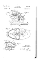
Referring to the drawings I generally indicates an outer housing the upper portion 2 of which may serve as the combustion chamber of a heater or stove. 3 are downward extensions or supporting legs defining between them air inlet apertures or gaps 4. 5 is a transversely extending partition centrally apertured as at 6 to permit air to enter about the pot 'I. The pot 'I has a generally concave bottom 8 through which liquid fuel may be delivered along an inlet duct 9. The pot has an upper flange ID resting upon a supporting partition or angle ring II. The otherwise open I2 having a central aperture I3. Air is admitted to the interior of the pot through a plurality of primary air inlets I4 circumferentially spaced about the side wall of the pot and arranged at varying distances from the ends of the pot. Secondary air may be admitted by the secondary air inlet apertures I5 which are shown as larger and more closely spaced than the primary air inlets I4. They are preferably upwardly inclined toward the aperture I3 of the flame ring. It will be understood that the invention may be applied to other types of burner but the type herein described and shown in Figure l is well adapted for use, with the particular control device or system herein described and shown, It will be understood that liquid Afuel is delivered, at varying rates of iiow, along the ducts 9 to the interior of the burner pot. In Figure l is illustrated a vertically axised pot in which the liquid fuel is delivered to the concave bottom 8 of the pot and is vaporized in response to combustion taking place in or above the pot. As the liquid fuel is vaporized it is mixed with primary air from the apertures I4, which produces a primary or partly combustible mixture. This primary mixture moves toward the apertures I3 of the flame end of the pot is partially closed by a flame ring ring and receives secondary air through the apertures I5. The iinal mixture thus formed is burned at or above the top of the pot. It will be understood that where the pot is horizontally axised or arranged otherwise as shown in Figure l, any suitable means may be provided for receiving the liquid fuel for vaporization.
The rate of iiow of the fuel may vary from a minimum or pilot stage to` high re stage. lin order to control the rate of ow of the liquid fuel I illustrate a known type of iioat valve assembly. It will be understood that liquid fuel from any suitable source may be delivered along an inlet duct 20,. It reaches the interior of the float valve housing 2l past any suitable valve diagrammatically indicated at 22. The level of liquid fuel in the housing 2I may be controlled by any suitable floats 23, 24, Since the details of the oat valve assembly do not of themselves form part of the present invention it will not be further described except to say that the rate of flow of liquid fuel along the duct 9 of the burner pot may be varied by rotation of the manual knob 26 or of axial movement of the control button 2I. The details .whereby this control are obtainedare not described. 28 indicates any suitable cover plate for the housingv 2l. It is apertured to permit the upward extension of the control button 2l. The oil control knob 26 is also located above the cover plate 28 which may be suitably calibrated as at 29 to permit manual control when necessary or desired. 38 indicates a housing removably positioned on -the top of the cover plate 28. Located within 1t is a slow moving reversing motor 3| which, through any suitable gear reduction 32, the detalls. of which do not form part of the present invention, rotates the threaded adjusting member 33 which is rotatably centered as by its lower portion 34 extending into any suitable bearing aperture 35a in the bottom element 35 of the housing 38. Movable along the screw 33 is a nut 36 having an upper enlarged portion 31 forming a ledge bearing against the top of a thrust member 38. The nut has a portion 38 which extends through the thrust member and is xed in relation thereto. Rotation of the thrust member and of the nut is prevented by the pin 40 which extends through and into the thrust member. The opposite end of the thrust member extends outwardly through a gap or aperture 4| in the side wall of the housing 30 and overlies the oil flow controlling button 21. It will be understood that the button 21 is normally moved toward minimum flow position as by any suitable spring means 21a. As the button 21 is depressed the rate of flow of liquid fuel along the duct 8 to the burner is increased. It will be understood that as the screw 33 is rotated in one direction it may be employed to move the thrust member 38 downwardly against the button 21, from the full line to the dotted line position of Figure 4,
thus increasing the rate of fuel flow to the burner. Rotation of the reversing motor 3| in the opposite direction will move the member 38 upwardly and the spring 21a will raise the pin 21 and decrease the rate of flow of liquid fuel to the burner. If it is desired to operate the device manually the modulating control can be cut out by rotating the pivoted member 45, from the full line to the dotted line position of Figure 3. This unmasks an aperture 46 in the member 38 through which the button 21 may pass, and modulating control is terminated.
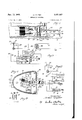
Referring to the wiring diagram of Figure 5, 50, 5| indicates a line circuit from any suitable source of electric power. T is a transformer having a primary coil 52; a core 53, and a secondary coil 54. The secondary or low voltage circuit may be traced as follows: A conductor 55 extends to any suitable room thermostat, to the thermostatic leaf or warping bar 56. The thermostat is shown as having two normally fixed contacts 51 and 58. 59 is a conductor extending from the contact 51 to the limit switch contact opposed to the contact 6|. 62 is a conductor extending from the contact 6| to the reversible motor 3|.
63 is a conductor extending from the reversible motor to the transformer secondary coil 54. From the thermostat contact 58 is a conductor 65 which extends to the limit switch contact 66. From the opposite limit switch contact 61 a conductor 68 extends to the reversible motor. The circuit is continued by a conductor 69 extending to the conductor 63 and thus to the coil 54.
With reference to Figures 4 and 5 it will be noted that the movable limit switch contacts or blades 60 and 66 are in the line of movement of the member 38. Thus the limit of the adjustment of the button 21 by the member 38 is controlled, and the circuit for the reversible motor is broken, at each limit of movement of the 4 member 38, by the irnpingement of the member 38 against the member 66 or 6 8.
With reference to the form of Figures 6 to 8 inclusive, the member 38a is provided with an offset 38h which performs the same function as the corresponding offset in the form of Figure 3, but is inclined to the rest of the member 38. Secured to the member 38a is a pin 60 of insulating material which is adapted to operate the intermediate movable switch member 6| which is movable between the normally fixed switch members 62 and 63. The switch members 6|, 62 and 63 are connected'in parallel with the members 56, 51 and 58 of the room thermostat. The wiring diagram is otherwise identical with the diagrammatic showing of Figure 5 and like parts are given like indicating symbols. It will be understood that the pin 68 is effective to keep either the switch members 6| and 62 or switch members 6| and 63 in closed position, regardless of the position of the thermostat leaf 56, when the pin 60 is at the right level in the vertical travel of the member 38a. Thus any predetermined range may be cut out, and modulation may be prevented, for example in the range between pilot fire and intermediate fire. The range through which the pin 60 is effective to prevent modulation may be varied to suit particular conditions, by a suitable variation in the size, location and proportion of the pin and the cooperating switch parts.
It will be realized that, whereas, I have described and illustrated a practical and operative device, nevertheless many changes may be made in the size, shape, number and disposition of parts without departing from the spirit of the invention. I therefore wish my description and drawings to be taken as in a broad sense illustrative or diagrammatic, rather than as limiting me to my precise showing.
For instance the system may be employed with a wide variety of oil burners and may also be employed with burners employing a gaseous fuel, where modulation of the rate of fuel delivery is desired.
The use and operation of the invention are as follows:
The invention is illustrated in connection with a natural draft burner of the hydroxylating pot type. The floating or modulating control is superimposed on the normal manually operable oil ow control in which the knob 26 may be used for manual adjustment of any suitable oil flow controlling valve which controls the rate of flow of fuel along the duct 9. If the user prefers to employ the manual controlor if the modulating control is out of order, the user can move the blade 45 to the dotted line position of Figure 3, thereby permitting the button 21 to extend through the aperture 46 of the member 38. This entirely interrupts the operation of the actuating connection between the modulating control system and the oil flow supply.
Assume that the device is operating as a floating or modulating control, with the blade ,45 masking the aperture 46, then the modulating system works on the button 21. As the button21 is spring thrust upwardly to the limit of its possible upward movement, its downward movement and its return upward movement is entirely controlled by downward and'upward movement of the member 38.
Assume that the house thermostat is satisfied and the leaf or contact 56 is in the intermediate position in which it is shown in Figure 5, the reversible motor is not energized and is not rotated, and the nut 36 is in fixed position, and with it the member 38. Assume that there is a change in the temperature of the heated space and the thermostat leaf 56 moves to close the cold contact, calling for heat, a circuit is closed through the reversible motor, and its rotor begins to rotate and drive the nut 36. Rotation of the member 33 is then effective to depress the nut 36 and with it the member 38 and the button 21. The rate of now of liquid fuel increases, and the burner burns at a higher stage. Shortly an increase in the temperature of the heated space returns the thermostat leaf 56 to intermediate position. If the result is overheating, then the leaf 56 contacts the opposite or hot contact and the reversible motor rotates in the opposite direction. The result is to raise the member 38 and to permit the spring 21a to raise the button 21 and to decrease the rate of flow of the liquid fuel. In practice a balance is shortly reached, with the thermostat satised and the leaf 56 in intermediate position, the rate of iiow of liquid fuel being properly controlled in relation tothe necessary heat delivery to the heated space.
The upward and downward limit of movement of the button 21, or the maximum and minimum weight of liquid fuel flow, may be controlled by the limit switches shown for example in Figures 4 and 5. When the member 38 breaks the limit switch contact 65, the button 21 can go no higher, and a minimum possible ilow is thus provided. Similarly when the member 38 breaks the limit switch contact Bil, the button 21 can go no lower, and this establishes a maximum fuel flow rate. If desired anticipators such as the resistances 1t! and 'll may be associated with the limit switch leaves or contacts E@ and 66 which, in that event, may be bi-metals, spring or warping bars. Any suitable circuit for the anticipators may be employed including the conductors. A
The limit switches may be so positioned that there is a small amount of excess travel of the leaf spring, so that in the iinal position the oil stem button 21 will be all the way up, or all the way down, on the pilot re. Any excess travel downward maybe taken up vin the spring action of the leaf spring. In the actual operation of the device, when the thermostat blade 56 stands between the contacts 51 and 58, the reversible motor 3l is stationary and the oil stem button 21 remains at its point of last setting. The thermostat is effective, after modulation, to set the oil flow to maintain the heat output at just the right amount to keep the thermostat satised.
The above described control is suitable not only for new installations but can be adapted to present field installations, since it can be attached to float valve assemblies which are already on the market and in common use. It has the further advantage that in the case of failure, such as current failure, manual control can be resorted to by the use of the manual knob 26. Whereas in Figure 5 a transformer is illustrated for permitting the above modulating control system to be operated from commercial line current, an ordinary low voltage battery may be employed, since low voltage reversing motors are available.
By employing the switch mechanism 60, 6I, 62 and 63 of Figure 6, I can also out out the modulation through any desired range in the travel of the member 38a between the limit switches 60 and 66.
I claim:
1. In a control for oil burner iloat valve assemblies having a primary manually operable valve control member and a secondary valve control member, means for controlling the secondary valve control member including a reversible rotary motor, a movable control member adapted to be opposed to said secondary control member, a driving connection between said reversible motor and said movable control member, means for causing said motor to rotate in one direction in response to overheating of the space to be heated and for causing it to rotate in an opposite directionl in response to underheating of the space to be heated, limit switch means, in circuit with said reversible motor, adapted to limit the possible excursion of said movable control member in either direction, and means for terminating the actuating connection between the movable control member and the secondary valve control member without otherwise effecting the operation of the control.
2. In a conversion unit adapted to be applied to a float valve assembly for liquid fuel valve assemblies having an exterior manual control knob and an exteriorly extending secondary valve control element, a housing, a reversible rotary motor in said housing, a control arm having a portion aligned with and opposable to said secondary valve control member, means for moving said control arm in response to rotation of said reversible motor in either direction, said control arm being apertured in alignment with said secondary valve control member, means for normally closing said aperture and for thereby maintaining an operative relationship between said control arm and said secondary valve control member, including a closure for said aperture adapted to be moved to aperture opening position, whereby, when said closure is so moved, the actuating connection between the valve control member and the control arm is terminated.
3. In a conversion unit adapted to be applied to a float valve assembly for liquid fuel valve assemblies having an exterior manual control knob and an exteriorly extending secondary valve control element, a housing, a reversible rotary motor in said housing, a control arm having a portion aligned with and opposable to said secondary valve control member, means for moving said control arm in response to rotation of said reversible motor in either direction, means for normally maintaining an operative relationship between said control arm and said secondary valve control, and for interrupting said operative relationship while permitting movement of said control arm and rotation of said motor.
4. In combination with a float valve housing having a ilow control member projecting for longitudinal movement, a control housing mounted on the valve housing, a reversing motor and an actuating member in the control housing, a screw and nut connection between them whereby motor rotation displaces the actuating member laterally, a connection between the actuating member and the flow control member whereby movement of the actuating member operates the flow control member, an electric circuit including the motor and having forward and reverse branches, limit switches, one in each branch in opposition to the actuating member whereby at each end of its excursion it operates one of the switches, a room thermostat having contacts adapted selectively to energize one of the motor circuit branches, a by-pass circuit in parallel with the thermostat, a selector switch therein, connections between the selector switch and the limit switch controlled circuits, means carried by the actuating member for operating the selector switch to connect the by-pass circuit selectively to one of the motor circuit branches.
5. In combination with a iloat valve housing having a flow control member projecting for longitudinal movement, a control housing mounted on the valve housing, a reversing motor and an actuating member in the control'housing, a screw and nut connection between them Whereby motor rotation displaces the actuating member laterally, a connection between the actuating member of the flow control member whereby movement of the actuating member operates the flow control member, an electric circuit including the motor and having forward and reverse branches, limit switches, one in each branch in opposition to the actuating member whereby at each end of its excursion it operates one of the switches, a room thermostat having contacts adapted selectively to energize one of the motor A circuit branches, a by-pass circuit in parallel with REFERENCES CITED The following references are of record in the tlle of this patent:
UNITED STATES PATENTS Number Name Date 856,417 Olson June 11, 1907 2,028,110 Taylor Jan. 14, 1936 2,086,482 Stewart et al July 6, 1937 2,317,063v Johnson Apr. 20, 1943
Priority Applications (1)
| Application Number | Priority Date | Filing Date | Title |
|---|---|---|---|
| US577084A US2481663A (en) | 1945-02-09 | 1945-02-09 | Modulating control |
Applications Claiming Priority (1)
| Application Number | Priority Date | Filing Date | Title |
|---|---|---|---|
| US577084A US2481663A (en) | 1945-02-09 | 1945-02-09 | Modulating control |
Publications (1)
| Publication Number | Publication Date |
|---|---|
| US2481663A true US2481663A (en) | 1949-09-13 |
Family
ID=24307205
Family Applications (1)
| Application Number | Title | Priority Date | Filing Date |
|---|---|---|---|
| US577084A Expired - Lifetime US2481663A (en) | 1945-02-09 | 1945-02-09 | Modulating control |
Country Status (1)
| Country | Link |
|---|---|
| US (1) | US2481663A (en) |
Citations (4)
| Publication number | Priority date | Publication date | Assignee | Title |
|---|---|---|---|---|
| US856417A (en) * | 1905-03-20 | 1907-06-11 | John A Olson | Electrical controller for steam plants, &c. |
| US2028110A (en) * | 1935-04-08 | 1936-01-14 | Honeywell Regulator Co | Remote control system |
| US2086482A (en) * | 1931-11-12 | 1937-07-06 | Howard D Colman | Control for air conditioning systems |
| US2317063A (en) * | 1940-04-04 | 1943-04-20 | Roy W Johnson | Conversion oil control device |
-
1945
- 1945-02-09 US US577084A patent/US2481663A/en not_active Expired - Lifetime
Patent Citations (4)
| Publication number | Priority date | Publication date | Assignee | Title |
|---|---|---|---|---|
| US856417A (en) * | 1905-03-20 | 1907-06-11 | John A Olson | Electrical controller for steam plants, &c. |
| US2086482A (en) * | 1931-11-12 | 1937-07-06 | Howard D Colman | Control for air conditioning systems |
| US2028110A (en) * | 1935-04-08 | 1936-01-14 | Honeywell Regulator Co | Remote control system |
| US2317063A (en) * | 1940-04-04 | 1943-04-20 | Roy W Johnson | Conversion oil control device |
Similar Documents
| Publication | Publication Date | Title |
|---|---|---|
| US2685917A (en) | Oil burner | |
| US2291805A (en) | Burner control system | |
| US2251055A (en) | Control mechanism for fluid fuel burners | |
| US2237041A (en) | Fuel control for fluid fuel burners | |
| US2481663A (en) | Modulating control | |
| US2396205A (en) | Controlling means | |
| US1832090A (en) | Valve operating mechanism | |
| US2075314A (en) | Air conditioning apparatus | |
| US2569877A (en) | Thermostatically controlled vaporizing fuel burner | |
| US1786901A (en) | Fluid-fuel heating system | |
| US2456170A (en) | Liquid fuel burner control | |
| US2336730A (en) | Thermostatic float valve adjustment | |
| US2337476A (en) | Control apparatus | |
| US2369739A (en) | Oil control device | |
| US3047273A (en) | Air conditioning apparatus | |
| US2655987A (en) | Combination oil-gas fired conversion burner | |
| US2348143A (en) | Control for combustion apparatus | |
| US2247689A (en) | Liquid fuel burning apparatus | |
| US2286137A (en) | Furnace control | |
| US1853196A (en) | Gas burner control system | |
| US2012100A (en) | Liquid fuel burner | |
| US2244631A (en) | Temperature regulation | |
| US2353498A (en) | Valve operated motor controlling switch | |
| US2255917A (en) | Automatic air shutter for oil burners | |
| US2476807A (en) | Control for oil burners |