US855713A - Self-exciting alternator. - Google Patents
Self-exciting alternator. Download PDFInfo
- Publication number
- US855713A US855713A US29126205A US1905291262A US855713A US 855713 A US855713 A US 855713A US 29126205 A US29126205 A US 29126205A US 1905291262 A US1905291262 A US 1905291262A US 855713 A US855713 A US 855713A
- Authority
- US
- United States
- Prior art keywords
- armature
- field
- magnetic
- self
- polar
- Prior art date
- Legal status (The legal status is an assumption and is not a legal conclusion. Google has not performed a legal analysis and makes no representation as to the accuracy of the status listed.)
- Expired - Lifetime
Links
- XEEYBQQBJWHFJM-UHFFFAOYSA-N Iron Chemical compound [Fe] XEEYBQQBJWHFJM-UHFFFAOYSA-N 0.000 description 10
- 238000004804 winding Methods 0.000 description 8
- 230000004907 flux Effects 0.000 description 5
- 229910052742 iron Inorganic materials 0.000 description 5
- 230000000694 effects Effects 0.000 description 3
- 230000005415 magnetization Effects 0.000 description 3
- 208000019901 Anxiety disease Diseases 0.000 description 1
- 241001674044 Blattodea Species 0.000 description 1
- 230000003247 decreasing effect Effects 0.000 description 1
- 239000000428 dust Substances 0.000 description 1
- 230000005284 excitation Effects 0.000 description 1
- 239000002360 explosive Substances 0.000 description 1
- 238000009413 insulation Methods 0.000 description 1
- YWXYYJSYQOXTPL-SLPGGIOYSA-N isosorbide mononitrate Chemical compound [O-][N+](=O)O[C@@H]1CO[C@@H]2[C@@H](O)CO[C@@H]21 YWXYYJSYQOXTPL-SLPGGIOYSA-N 0.000 description 1
- 239000000463 material Substances 0.000 description 1
- 239000000203 mixture Substances 0.000 description 1
Images

Classifications
-
- H—ELECTRICITY
- H02—GENERATION; CONVERSION OR DISTRIBUTION OF ELECTRIC POWER
- H02K—DYNAMO-ELECTRIC MACHINES
- H02K21/00—Synchronous motors having permanent magnets; Synchronous generators having permanent magnets
- H02K21/26—Synchronous motors having permanent magnets; Synchronous generators having permanent magnets with rotating armatures and stationary magnets
- H02K21/28—Synchronous motors having permanent magnets; Synchronous generators having permanent magnets with rotating armatures and stationary magnets with armatures rotating within the magnets
- H02K21/32—Synchronous motors having permanent magnets; Synchronous generators having permanent magnets with rotating armatures and stationary magnets with armatures rotating within the magnets having horse-shoe magnets
- H02K21/325—Synchronous motors having permanent magnets; Synchronous generators having permanent magnets with rotating armatures and stationary magnets with armatures rotating within the magnets having horse-shoe magnets with the axis of the rotating armature perpendicular to the plane of the magnet
Definitions
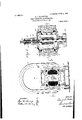
- Figure 1 is a central vertical the plane of the line lel of Fig. 2; .Fig. 2 is a horizontal section onftheplane of the line 2 -2 of 1; Fig. is a diagrammatic view.
- the numeral 1 designates a base of suitable material upon which are mounted said p prevent eddy currents, and held rigidly apart from each other by two nonmagnetic end plates 3 and 4 through which I pass suitable bolts 5. Permanent magnets The rotation of this proximity to magnetic proper windings caused the alternating currents induced in these windings to reach cured by su1table means against the outer ar projections 2, developing jections two A plate 7 bridges the u per part of the structure to properly inc ose the armature in a dust proof case.
- he armature 8 is preferably formed of a number of soft iron laminae secured together insulated rivets .9 and after being assembliedare keyed to the The form of
- the polar surfaces10 and 10 oppositely located on each side of the axial line are substantially circular in shape, while the oppositely located polar surfaces 11 and 11 are not concentric.
- the polar surfaces 10 and 10 being substantially circular in shape the edges 21 different intensities bemagnetic field threading through these reluctance of the same magnetic field was decreased. It is obvious that under the above conditions that one of the two currents reaching value has rents tending to field or to maintain it at least to a fairly permanent state of magnetization.
- the object of-the present invention is to apply this same principle to the magnetization of the permanent magnets of the alternating type of shuttle wound Siemens magn degrees the air ga It s known that the rota ting element of this (1 between the poles N and S and the polar surfaces 11-11 of the armature, which is initially very large, will gradually decrease until the armature has com leted its rotation through 90 degrees.
- armature 8 Upon the armature 8 is wound a coil 12 in the usual manner and protected by suitable insulation 13. One terminal of the winding is grounded, the other terminal being led through an insulatedbushing 14 to a conpin 15 secured in the hollow shaft 22 and insulated therefrom by a bushing 16. A. brush 17 insulated from the cap 4 is pressed against revolving pin 15 by a spring 18 in electrical connection with a binding post 19.
- auxiliary coils In order to increase the magnetizing effect' of these auxiliary coils upon the total field I advance the phase of the current flowing through said auxiliary coils by placing a condenser 23 in shunt with them thus causing the maximum current to take place while the armature edges 21 and 21 being in close proximity to the edges of the poles N andS presents a fiirly good magnetic path for the auxiliary
- the shaft 22 may be driven from any suitable source of power through a gear 24.
- a partially self exciting alternator having a-permanent magnetic field, polar projections of soft iron adjacent to the magnetic poles developed by said field, a rotor having dissymmetric polar faces adapted to rotate ducting soft iron polar projections said coils being connected in series with each other and in shunt with said rotor winding, whereby the waves of the alternating current generated which have a magnetizing effect on the permanent magnetic field reach a higher value than those which have feet on said field and the magnetizing effect being increased by the location of theauxiliary windings in the magnetic circuit.
- a partially self exciting alternator having a permanent magnetic field, polar projections of soft iron adjacent to the magnetic poles developed by said field, a rotor having dissymmetric polar faces adapted to rotate in close proximity to said poles, a winding on said rotor auxiliary coils wound around said soft iron polar projections said coils' being connected in series with each other and in shunt with said rotor windings, and a condenser connected in shunt with said auxiliary coils, whereby the phase of the auxiliary magnetizing current is sufficiently advanced to enable the auxiliary magnetic field thus set up to exert its action on the main field while the rotor by its position in the field presents a path of sufficiently low magnetic reluctance.
Landscapes
- Engineering & Computer Science (AREA)
- Power Engineering (AREA)
- Synchronous Machinery (AREA)
Description
.PATENTED JUNE 4, 1907.
L. I. LE PONTOIS. SELF EXCITING ALTERNATOR.
APPLIOATION TILED DEC. 11, 1905.
2 SHEETBBHBET 1.
No. 855,713. PATENTED JUNE 4, 1907. L. J. LB PONTOIS.
SELF EXCITING ALTERNATOR.
APPLIGATION FILED DEO.11,1905.
2 SHEBTS-SHEET 2.
Angsts I 0a r ATTORNEY i poles surrounded by cause the rate at whichthe reluctance of the UNITED STATES PATENT OFFICE. LEON LE ro 'ro'rsI or New noonannn, NEW PQLYQPIIASE .IGNITIGN SYSTEM COIVIPANY, A YORK."
YORK, ASSIGNOR TO CORPORATION OF NEW szLF- sxosrme ALTERNATOR.
Specification of il' etters latent. Patented 'il'une, 190?. e iieeeien filed December 1 1, 1905; "senel No. 291.262. I Y
necsmia To all whom itfmay concern: I I Be it known that I, LEON J. Lu PONTOIS, a citizen of the Republic of France, and a resiilent of New Rochelle, Westchester county, New York, haveinvented certain new and useful Improvements in Self-Exciting Alternators', of which thefollowing is a specification. I 4
In my Patent-808,555 dated December 26, 1905, I have described an alternating current magneto of the inductor type designed primarily to deliver suitable currents to socalled spark coils usedfor theignition of explosive mixtures tern, said magneto resenting a very portant feature, in tli at, without the use of .rectifying means the alternating current generatedwas partially utilized in maintaining the so-called permanent magnets, constituting the field of the magneto to a really ence to which v.
Figure 1 is a central vertical the plane of the line lel of Fig. 2; .Fig. 2 is a horizontal section onftheplane of the line 2 -2 of 1; Fig. is a diagrammatic view.
the accompanying drawings in .Similar reference numerals indicate similar parts throughout the several views Referring to the drawings the numeral 1 designates a base of suitable material upon which are mounted said p prevent eddy currents, and held rigidly apart from each other by two nonmagnetic end plates 3 and 4 through which I pass suitable bolts 5. Permanent magnets The rotation of this proximity to magnetic proper windings caused the alternating currents induced in these windings to reach cured by su1table means against the outer ar projections 2, developing jections two A plate 7 bridges the u per part of the structure to properly inc ose the armature in a dust proof case.
he armature 8 is preferably formed of a number of soft iron laminae secured together insulated rivets .9 and after being assembliedare keyed to the The form of The polar surfaces10 and 10 oppositely located on each side of the axial line are substantially circular in shape, while the oppositely located polar surfaces 11 and 11 are not concentric. The polar surfaces 10 and 10 being substantially circular in shape the edges 21 different intensities bemagnetic field threading through these reluctance of the same magnetic field was decreased. It is obvious that under the above conditions that one of the two currents reaching value has rents tending to field or to maintain it at least to a fairly permanent state of magnetization.
The object of-the present invention is to apply this same principle to the magnetization of the permanent magnets of the alternating type of shuttle wound Siemens magn degrees the air ga It s known that the rota ting element of this (1 between the poles N and S and the polar surfaces 11-11 of the armature, which is initially very large, will gradually decrease until the armature has com leted its rotation through 90 degrees. It will follow, therefore, that the reluctance of the The invention will be understobd l ly-refer section on 6, four being shown in the drawings, are semagnetic flux induced by the permanent reason I locate two auxiliary field coils 20 on magnets in the magnetic circuit, comprising the edges of the poles N and 'S, which coils themselves, the polar pro ections are in series with each other and are prefer- Z2, the air gaps between the armature and said polar projections, and the armature, will decrease very gradually, attaining its minimum when the armature reaches a position at right angles to that-shown. When the armature rotates from this latter position to the position shown in Fig. 1 the magnetic reluctance of the field will increase at a very slow rate up to the point where the polar surfaces 10-10 abruptly leave the edges of the poles N and S. It will be seen by the drawing that the air gap increases very suddenly with a slight angular motion of the armature.
Upon the armature 8 is wound a coil 12 in the usual manner and protected by suitable insulation 13. One terminal of the winding is grounded, the other terminal being led through an insulatedbushing 14 to a conpin 15 secured in the hollow shaft 22 and insulated therefrom by a bushing 16. A. brush 17 insulated from the cap 4 is pressed against revolving pin 15 by a spring 18 in electrical connection with a binding post 19.
From the above description it will be seen that an alternating current wave will e generated in the armature circuit while it rotates in the direction of the arrow from the position shown in Fig. 1 to a position at right angles thereto. During that period of rotation the intensity of the magnetic fiux threading through the armature coil will increase rogressively from zero to a maximum va ue, but as this increase is very radual the current wave may be represented by the curve a of Fig. 8. During the retation of the armature from this last de scribed position to that shown in Fig. 1 the magnetic flux threading through the armature coil'will at first decrease very slowly, but as the armature ap roaches the edges of the oles N and S it decrease abruptly caus ing thereby a sudden and rapid increase in the rate of change of the intensity of the magnetic flux threading through the coil 12 and a subsequent sudden rise in value of the current induced in the armature coil. It will be noticed that the field created in the armature by this induced current tends to increase the intensity of the total magnetic flux issuing from the permanent magnets, but owing to the fact that when that auxiliary field excitation takes place the axis of the armature forms a considerable angle with the axis of the permanent magnetic flux, the auxiliary magnetization is not felt as well by the permanent magnetic field as if the axis of both fields coincided. For this ably connected in shunt across the armature circuit as shown in Fig. 4. In order to increase the magnetizing effect' of these auxiliary coils upon the total field I advance the phase of the current flowing through said auxiliary coils by placing a condenser 23 in shunt with them thus causing the maximum current to take place while the armature edges 21 and 21 being in close proximity to the edges of the poles N andS presents a fiirly good magnetic path for the auxiliary The shaft 22 may be driven from any suitable source of power through a gear 24.
What I claim and desire to secure by Letters Patent is:
1. A partially self exciting alternator having a-permanent magnetic field, polar projections of soft iron adjacent to the magnetic poles developed by said field, a rotor having dissymmetric polar faces adapted to rotate ducting soft iron polar projections said coils being connected in series with each other and in shunt with said rotor winding, whereby the waves of the alternating current generated which have a magnetizing effect on the permanent magnetic field reach a higher value than those which have feet on said field and the magnetizing effect being increased by the location of theauxiliary windings in the magnetic circuit.
2. A partially self exciting alternator having a permanent magnetic field, polar projections of soft iron adjacent to the magnetic poles developed by said field, a rotor having dissymmetric polar faces adapted to rotate in close proximity to said poles, a winding on said rotor auxiliary coils wound around said soft iron polar projections said coils' being connected in series with each other and in shunt with said rotor windings, and a condenser connected in shunt with said auxiliary coils, whereby the phase of the auxiliary magnetizing current is sufficiently advanced to enable the auxiliary magnetic field thus set up to exert its action on the main field while the rotor by its position in the field presents a path of sufficiently low magnetic reluctance.
In testimony whereof I have hereunto signed my name in the presence of two subscribing witnesses.
. LEON J. LE PONTOIS. Witnesses:
'OLIN AuFo's'rnn, GEORGE W. Youuo.
in close proxim1 t'y to said poles, a winding on said rotor auxiliary COIlS'WOUIld around saida demagnetizing ef-
Priority Applications (1)
| Application Number | Priority Date | Filing Date | Title |
|---|---|---|---|
| US29126205A US855713A (en) | 1905-12-11 | 1905-12-11 | Self-exciting alternator. |
Applications Claiming Priority (1)
| Application Number | Priority Date | Filing Date | Title |
|---|---|---|---|
| US29126205A US855713A (en) | 1905-12-11 | 1905-12-11 | Self-exciting alternator. |
Publications (1)
| Publication Number | Publication Date |
|---|---|
| US855713A true US855713A (en) | 1907-06-04 |
Family
ID=2924168
Family Applications (1)
| Application Number | Title | Priority Date | Filing Date |
|---|---|---|---|
| US29126205A Expired - Lifetime US855713A (en) | 1905-12-11 | 1905-12-11 | Self-exciting alternator. |
Country Status (1)
| Country | Link |
|---|---|
| US (1) | US855713A (en) |
Cited By (1)
| Publication number | Priority date | Publication date | Assignee | Title |
|---|---|---|---|---|
| US2710930A (en) * | 1952-11-15 | 1955-06-14 | Automatic Elect Lab | Hand generator |
-
1905
- 1905-12-11 US US29126205A patent/US855713A/en not_active Expired - Lifetime
Cited By (1)
| Publication number | Priority date | Publication date | Assignee | Title |
|---|---|---|---|---|
| US2710930A (en) * | 1952-11-15 | 1955-06-14 | Automatic Elect Lab | Hand generator |
Similar Documents
| Publication | Publication Date | Title |
|---|---|---|
| JPS62147936A (en) | Electric rotary apparatus | |
| JP4082445B2 (en) | Electronically switched two-phase reluctance machine | |
| US3132272A (en) | Dynamo-electric machines | |
| US1653946A (en) | Electric step-by-step motor | |
| US2230878A (en) | Magnetoelectric ignition apparatus | |
| US3283190A (en) | Dynamoelectric machine | |
| US855713A (en) | Self-exciting alternator. | |
| US579012A (en) | scheeffer | |
| US2713128A (en) | Dynamoelectric machine | |
| US1234914A (en) | Dynamo-electric machine. | |
| US1545422A (en) | Dynamo-electric machine | |
| US925499A (en) | Dynamo-electric machinery. | |
| US1401883A (en) | Dynamo-electric generator | |
| US399800A (en) | Dynamo-electric machine | |
| US1056360A (en) | Inductor-generator for ignition purposes. | |
| US752692A (en) | Leon jules le pontois | |
| US947647A (en) | Inductor-generator for ignition purposes. | |
| US1081760A (en) | Ignition-dynamo. | |
| US6734593B2 (en) | Alternating current generator with unpolarized rotor | |
| US1183286A (en) | Dynamo-electric machine. | |
| USRE14373E (en) | Ignition-dynamo | |
| US500301A (en) | Setts | |
| US550464A (en) | Necticut | |
| US1160995A (en) | Magneto-electric machine. | |
| USRE14181E (en) | Assighos |