US8553529B2 - Method and apparatus for performing a HARQ operation in a multi-carrier system - Google Patents
Method and apparatus for performing a HARQ operation in a multi-carrier system Download PDFInfo
- Publication number
- US8553529B2 US8553529B2 US13/057,704 US200913057704A US8553529B2 US 8553529 B2 US8553529 B2 US 8553529B2 US 200913057704 A US200913057704 A US 200913057704A US 8553529 B2 US8553529 B2 US 8553529B2
- Authority
- US
- United States
- Prior art keywords
- phich
- carrier
- index
- uplink
- group
- Prior art date
- Legal status (The legal status is an assumption and is not a legal conclusion. Google has not performed a legal analysis and makes no representation as to the accuracy of the status listed.)
- Expired - Fee Related, expires
Links
- 238000000034 method Methods 0.000 title claims abstract description 51
- 239000000969 carrier Substances 0.000 claims description 132
- 230000005540 biological transmission Effects 0.000 claims description 95
- 125000004122 cyclic group Chemical group 0.000 claims description 94
- 238000013507 mapping Methods 0.000 description 36
- 108010003272 Hyaluronate lyase Proteins 0.000 description 32
- 230000002776 aggregation Effects 0.000 description 21
- 238000004220 aggregation Methods 0.000 description 21
- 230000006870 function Effects 0.000 description 21
- 238000004891 communication Methods 0.000 description 16
- 238000013468 resource allocation Methods 0.000 description 13
- 230000015654 memory Effects 0.000 description 9
- 238000001228 spectrum Methods 0.000 description 9
- 230000001174 ascending effect Effects 0.000 description 6
- 230000008859 change Effects 0.000 description 5
- 230000001105 regulatory effect Effects 0.000 description 5
- 238000010586 diagram Methods 0.000 description 4
- 230000007774 longterm Effects 0.000 description 4
- 230000008569 process Effects 0.000 description 4
- 230000011664 signaling Effects 0.000 description 4
- 230000000694 effects Effects 0.000 description 3
- 230000008901 benefit Effects 0.000 description 2
- 238000007796 conventional method Methods 0.000 description 2
- 239000013256 coordination polymer Substances 0.000 description 2
- 230000003247 decreasing effect Effects 0.000 description 2
- 238000001514 detection method Methods 0.000 description 2
- 230000006866 deterioration Effects 0.000 description 2
- 238000012545 processing Methods 0.000 description 2
- 230000004913 activation Effects 0.000 description 1
- 230000004931 aggregating effect Effects 0.000 description 1
- 239000011159 matrix material Substances 0.000 description 1
- 238000010295 mobile communication Methods 0.000 description 1
- 238000012544 monitoring process Methods 0.000 description 1
- 230000010363 phase shift Effects 0.000 description 1
- 230000004044 response Effects 0.000 description 1
- 230000000630 rising effect Effects 0.000 description 1
- 230000007480 spreading Effects 0.000 description 1
Images


Classifications
-
- H—ELECTRICITY
- H04—ELECTRIC COMMUNICATION TECHNIQUE
- H04L—TRANSMISSION OF DIGITAL INFORMATION, e.g. TELEGRAPHIC COMMUNICATION
- H04L1/00—Arrangements for detecting or preventing errors in the information received
- H04L1/12—Arrangements for detecting or preventing errors in the information received by using return channel
- H04L1/16—Arrangements for detecting or preventing errors in the information received by using return channel in which the return channel carries supervisory signals, e.g. repetition request signals
- H04L1/18—Automatic repetition systems, e.g. Van Duuren systems
- H04L1/1829—Arrangements specially adapted for the receiver end
- H04L1/1854—Scheduling and prioritising arrangements
-
- H—ELECTRICITY
- H04—ELECTRIC COMMUNICATION TECHNIQUE
- H04L—TRANSMISSION OF DIGITAL INFORMATION, e.g. TELEGRAPHIC COMMUNICATION
- H04L1/00—Arrangements for detecting or preventing errors in the information received
- H04L1/12—Arrangements for detecting or preventing errors in the information received by using return channel
- H04L1/16—Arrangements for detecting or preventing errors in the information received by using return channel in which the return channel carries supervisory signals, e.g. repetition request signals
- H04L1/18—Automatic repetition systems, e.g. Van Duuren systems
- H04L1/1829—Arrangements specially adapted for the receiver end
- H04L1/1861—Physical mapping arrangements
-
- H—ELECTRICITY
- H04—ELECTRIC COMMUNICATION TECHNIQUE
- H04L—TRANSMISSION OF DIGITAL INFORMATION, e.g. TELEGRAPHIC COMMUNICATION
- H04L5/00—Arrangements affording multiple use of the transmission path
- H04L5/0001—Arrangements for dividing the transmission path
- H04L5/0003—Two-dimensional division
- H04L5/0005—Time-frequency
- H04L5/0007—Time-frequency the frequencies being orthogonal, e.g. OFDM(A) or DMT
Definitions
- the present invention relates to wireless communications, and more particularly, to a method of performing hybrid automatic repeat request (HARQ) in a wireless communication system supporting multiple carriers.
- HARQ hybrid automatic repeat request
- Wireless communication systems are widely spread all over the world to provide various types of communication services such as voice or data.
- the wireless communication system is a multiple access system capable of supporting communication with multiple users by sharing available system resources (e.g., bandwidth, transmit power, etc.).
- Examples of the multiple access system include a code division multiple access (CDMA) system, a frequency division multiple access (FDMA) system, a time division multiple access (TDMA) system, an orthogonal frequency division multiple access (OFDMA) system, a single carrier frequency division multiple access (SC-FDMA) system, etc.
- CDMA code division multiple access
- FDMA frequency division multiple access
- TDMA time division multiple access
- OFDMA orthogonal frequency division multiple access
- SC-FDMA single carrier frequency division multiple access
- only one carrier is considered generally even if a bandwidth is differently set between an uplink and a downlink.
- the carrier is defined with a center frequency and a bandwidth.
- 3GPP 3 rd generation partnership project
- LIE long term evolution
- one carrier constitutes each of the uplink and the downlink, and the bandwidth of the uplink is symmetrical to the bandwidth of the downlink in general.
- 3GPP 3 rd generation partnership project
- LIE long term evolution
- a spectrum aggregation (or carrier aggregation) technique is being developed to obtain the same effect as when a band of a wide bandwidth is logically used by aggregating a plurality of physically non-contiguous bands (i.e., frequency bands) in a frequency domain.
- LTE is currently under study in the 3GPP and is one of the latest standards of mobile communication techniques. Wireless access of the LTE is referred to as an evolved-UMTS terrestrial radio access network (E-UTRAN).
- E-UTRAN evolved-UMTS terrestrial radio access network
- a 3GPP LTE system uses hybrid automatic repeat request (HARQ) to increase transmission efficiency.
- Downlink HARQ implies that, when a base station (BS) transmits downlink data, a user equipment (UE) transmits an acknowledgement (ACK)/not-acknowledgement (NACK) signal for the downlink data.
- ACK acknowledgement
- NACK not-acknowledgement
- Uplink HARQ implies that, when the UE transmits uplink data, the BS transmits an ACK/NACK signal for the uplink data.
- the BS when the UE transmits uplink data on a physical uplink shared channel (PUCCH), the BS sends an ACK/NACK signal on a physical hybrid-ARQ indicator channel (PHICH).
- the PHICH is a physical channel for carrying HARQ ACK/NACK, and is identified by the UE by using a resource used in PUSCH transmission and a cyclic shift of a demodulation-reference signal (DM-RS) used for demodulation.
- DM-RS demodulation-reference signal
- the 3GPP LTE considers only a single carrier. Therefore, an uplink carrier used in PUSCH transmission and a downlink carrier used in PHICH transmission are unique. However, there is a problem in that it is difficult to be directly applied to the multiple-carrier system.
- the present invention provides a method and apparatus for performing hybrid automatic repeat request (HARQ) in a multiple-carrier system.
- HARQ hybrid automatic repeat request
- a method of performing HARQ of a user equipment (UE) in a multiple-carrier system includes: transmitting uplink data on an uplink carrier; and receiving acknowledgement (ACK)/not-acknowledgement (NACK) for the uplink data on a downlink carrier associated with the uplink carrier, wherein the downlink carrier is associated on the basis of an index of the uplink carrier, a radio resource used for transmission of the uplink data, and a demodulation-reference signal (DM-RS) applied to the uplink data.
- ACK acknowledgement
- NACK not-acknowledgement
- DM-RS demodulation-reference signal
- a method of performing HARQ of a UE in a multiple-carrier system includes: receiving information regarding a downlink carrier associated with an uplink carrier; transmitting uplink data on a physical uplink shared channel (PUSCH) of the uplink carrier; and receiving ACK/NACK for the uplink data on a physical hybrid-ARQ indicator channel (PHICH) of the downlink carrier, wherein a radio resource used by the PHICH is identified by a PHICH group index and a sequence index used in a PHICH channel indicated by the PHICH group index, and the PHICH group index and the sequence index are determined based on the lowest physical resource block used for transmission of the PUSCH and a cyclic shift index of a DM-RS used for transmission of the PUSCH.
- PUSCH physical uplink shared channel
- PHICH physical hybrid-ARQ indicator channel
- a UE including: a radio frequency (RF) unit for transmitting and receiving a radio signal; and a processor coupled to the RF unit, wherein the processor transmits uplink data on a uplink carrier, receives information regarding a downlink carrier mapped to the uplink carrier by using a mapping rule, receives ACK/NACK for the uplink data on the downlink carrier, wherein the mapping rule is determined based on an index of the uplink carrier, the lowest physical resource block index in the uplink carrier, and a cyclic shift index of a DM-RS applied to the uplink data.
- RF radio frequency
- an uplink carrier and a downlink carrier can be flexibly allocated in a multiple-carrier system.
- An operation for performing hybrid automatic repeat request (HARQ) is provided.
- the present invention can apply to the multiple-carrier system while maintaining an operation of a legacy 3 rd generation partnership project (3GPP) long term evolution (LTE) system.
- 3GPP 3 rd generation partnership project
- LTE long term evolution
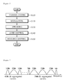
- FIG. 1 shows a wireless communication system
- FIG. 2 shows a structure of a radio frame in 3 rd generation partnership project (3GPP) long term evolution (LTE) system.
- 3GPP 3 rd generation partnership project
- LTE long term evolution
- FIG. 3 is a diagram showing an example of a resource grid for one downlink slot.
- FIG. 4 shows an example of a downlink subframe structure.
- FIG. 5 shows uplink hybrid automatic repeat request (HARQ).
- HARQ uplink hybrid automatic repeat request
- FIG. 6 is a flowchart showing a configuration of a physical hybrid-ARQ indicator channel (PHICH).
- PHICH physical hybrid-ARQ indicator channel
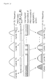
- FIG. 7 shows an example of asymmetric aggregation.
- FIG. 8 is a flowchart showing a method of performing HARQ in a multiple-carrier system.
- FIG. 9 shows a method of determining a PHICH resource according to an embodiment of the present invention.
- FIG. 10 shows an example of mapping between an uplink carrier and a downlink carrier.
- FIG. 11 shows another example of mapping between an uplink carrier and a downlink carrier.
- FIG. 12 shows a method of determining a PHICH resource according to an embodiment of the present invention.
- FIG. 13 shows indexing of a PHICH resource when a control region occupies 4 orthogonal frequency division multiplexing (OFDM) symbols.
- FIG. 14 is a block diagram showing a wireless communication system for implementing an embodiment of the present invention.
- 3rd generation partnership project (3GPP) long term evolution (LTE) is a part of an evolved-UMTS (E-UMTS) using evolved-universal terrestrial radio access network (E-UTRAN).
- the 3GPP LTE employs orthogonal frequency division multiple access (OFDMA) in a downlink and employs single carrier-frequency division multiple access (SC-FDMA) in an uplink.
- OFDMA orthogonal frequency division multiple access
- SC-FDMA single carrier-frequency division multiple access
- LTE-advanced (LTE-A) is an evolution of the 3GPP LTE.
- FIG. 1 shows a wireless communication system
- a wireless communication system 10 includes at least one base station (BS) 11 .
- Respective BSs 11 provide communication services to specific geographical regions (generally referred to as cells) 15 a , 15 b , and 15 c .
- the cell can be divided into a plurality of regions (also referred to as sectors).
- a user equipment (UE) 12 may be fixed or mobile, and may be referred to as another terminology, such as a mobile station (MS), a user terminal (UT), a subscriber station (SS), a wireless device, a personal digital assistant (PDA), a wireless modem, a handheld device, etc.
- the BS 11 is generally a fixed station that communicates with the UE 12 and may be referred to as another terminology, such as an evolved node-B (eNB), a base transceiver system (BTS), an access point, etc.
- eNB evolved node-B
- BTS base transceiver system
- access point etc.
- a downlink (DL) denotes communication from the BS to the UE
- an uplink (UL) denotes communication from the UE to the BS.
- a transmitter may be a part of the BS
- a receiver may be a part of the UE
- the transmitter may be a part of the UE
- the receiver may be a part of the BS.
- FIG. 2 shows a structure of a radio frame in 3GPP LTE.
- the radio frame consists of 10 subframes.
- One subframe consists of 2 slots.
- a time required for transmitting one subframe is defined as a transmission time interval (TTI).
- TTI transmission time interval
- one subframe may have a length of 1 millisecond (ms)
- one slot may have a length of 0.5 ms.
- One slot includes a plurality of orthogonal frequency division multiplexing (OFDM) symbols in a time domain and includes a plurality of resource blocks (RBs) in a frequency domain. Since the 3GPP LTE uses DL OFDMA, the OFDM. symbol is for representing one symbol period, and can be referred to as an SC-FDMA symbol or a symbol period according to a multiple-access scheme.
- OFDM orthogonal frequency division multiplexing
- the RB includes a plurality of contiguous subcarriers in one slot as a resource assignment unit.
- the structure of the radio frame is for exemplary purpose only, and the number of subframes included in the radio frame or the number of slots included in the subframe and the number of OFDM symbols included in the slot can change variously.
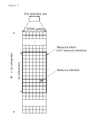
- FIG. 3 is a diagram showing an example of a resource grid for one DL slot.
- the DL slot includes a plurality of OFDM symbols in a time domain. Although it is described herein that one DL slot includes 7 OFDM symbols, and one RB includes 12 subcarriers in a frequency domain, the present invention is not limited thereto.
- Each element on the resource grid is referred to as a resource element (RE).
- One RB includes 12 ⁇ 7 REs.
- An RB group is an aggregation of four RBs.
- the number N DL of RBs included in the DL slot depends on a DL transmission bandwidth defined in a cell.
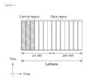
- FIG. 4 shows an example of a DL subframe structure.
- a subframe includes two slots. Up to three preceding OFDM symbols of a 1 st slot in the subframe correspond to a control region to which control channels are assigned. The remaining OFDM symbols correspond to a data region to which a physical downlink shared channel (PDSCH) is assigned.
- PDSCH physical downlink shared channel
- Examples of DL control channels used in 3GPP LTE include a physical control format indicator channel (PCFICH), a physical downlink control channel (PDCCH), a physical hybrid-ARQ indicator channel (PHICH), etc.
- PCFICH physical control format indicator channel
- PDCCH physical downlink control channel
- PHICH physical hybrid-ARQ indicator channel
- the PCFICH transmitted in a 1 st OFDM symbol of the subframe carries information regarding the number of OFDM symbols (i.e., a size of the control region) used for transmission of the control channels in the subframe.
- DCI downlink control information
- the DCI indicates UL resource allocation information, DL resource allocation information, and UL transmit power control commands for any UE group, etc.
- the PHICH carries an acknowledgement (ACK)/not-acknowledgement (NACK) signal for UL hybrid automatic repeat request (HARQ). That is, an ACK/NACK signal for UL data transmitted by a UE is transmitted on the PHICH.
- ACK acknowledgement
- NACK not-acknowledgement
- a PHICH duration denotes the number of OFDM symbols that can be used for PHICH transmission.
- the PDCCH can carry a downlink shared channel (DL-SCH)'s resource allocation and transmission format, an uplink shared channel (UL-SCH)'s resource allocation information, paging information regarding a paging channel (PCH), system information regarding the DL-SCH, a resource allocation of a higher-layer control message such as a random access response transmitted on the PDSCH, an aggregation of transmit power control commands for individual UEs in any UE group, activation of a voice over Internet (VoIP), etc.
- a plurality of PDCCHs can be transmitted in the control region, and a UE can monitor the plurality of PDCCHs.
- the PDCCH is transmitted on an aggregation of one or several consecutive control channel elements (CCEs).
- CCEs control channel elements
- the CCE is a logical allocation unit used to provide a coding rate depending on a state of a radio channel to the PDCCH.
- the CCE corresponds to a plurality of resource element groups. According to an association relation between the number of CCEs and a coding rate provided by the CCEs, a format of the PDCCH and the number of bits of an available PDCCH are determined. Control information transmitted on the PDCCH is referred to as downlink control information (DCI).
- DCI downlink control information
- the wireless communication system can support UL and/or DL hybrid automatic repeat request (HARQ).
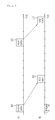
- FIG. 5 shows UL HARQ.
- a BS Upon receiving UL data 101 from a UE on a physical uplink shared channel (PUSCH), a BS transmits an ACK/NACK signal 102 on a PHICH after a specific time elapses.
- the ACK/NACK signal 102 corresponds to an ACK signal when the UL data 101 is successfully decoded, and corresponds to a NACK signal when the UL data 101 fails in decoding.
- the UE can transmit retransmission data 111 for the UL data 101 until ACK information is received or until up to a maximum number of retransmission attempts.
- the BS can transmit an ACK/NACK signal 112 for the retransmission data 111 on the PHICH.
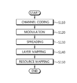
- FIG. 6 is a flowchart showing a configuration of a PHICH.
- the PHICH carries an ACK/NACK signal corresponding to a PUSCH for a UE.
- the section 6.9 of 3GPP TS 36.211 V8.2.0 (2008-03) “Technical specification Group Radio Access Network; Evolved Universal Terrestrial Radio Access (E-UTRA); Physical Channels and Modulation (Release 8)” can be incorporated herein by reference.
- the 1-bit ACK/NACK signal is subjected to channel coding by using repetition coding at a code rate of 1 ⁇ 3.
- step S 120 the ACK/NACK signal coded with a 3-bit codeword is mapped to 3 modulation symbols by using binary phase shift keying (BPSK).
- step S 130 the modulation symbols are spread by using a spreading factor (SF) N PHICH SF and an orthogonal sequence. The number of orthogonal sequences used in the spreading is double of N PHICH SF to apply I/Q multiplexing. 2N PHICH SF PHICHs which are spread by using 2N PHICH SF orthogonal sequences are defined as one PHICH group. PHICHs belonging to the same PHICH group are identified using different orthogonal sequences.
- step S 140 layer mapping is performed on the spread symbols according to a rank.
- step S 150 the layer-mapped symbols are mapped to respective resource elements.
- a PHICH resource corresponding to a PUSCH is defined by using I lowest — index PRB — RA which is the lowest physical resource block (PRB) index of a resource used in the PUSCH and n DMRS which is a cyclic shift of a demodulation reference signal (DM-RS) used in the PUSCH.
- the DM-RS is a reference signal used for demodulation of data transmitted on the PUSCH.
- the PHICH resource is known by an index pair (n group PHICH , n seq PHICH ).
- n group PHICH denotes a PHICH number
- n seq PHICH denotes an orthogonal sequence index in the PHICH group.
- n group PHICH and n seq PHICH are given by Equation 1 below.
- n PHICH group ( l PRB — RA lowest — index +n DMRS )mod N
- n PHICH seq ( ⁇ l PRB — RA lowest — index /N PHICH group ⁇ +n DMRS )mod 2 N SF PHICH [Equation 1]
- Equation 1 ‘mod’ denotes a modulo operation.
- n group PHICH has a value between 0 and (N group PHICH ⁇ 1), and the number N group PHICH of PHICH groups is defined by Equation 2 below.
- N PHICH group ⁇ ⁇ N g ⁇ ( N RB DL / 8 ) ⁇ for ⁇ ⁇ normal ⁇ ⁇ cyclic ⁇ ⁇ prefix 2 ⁇ ⁇ N g ⁇ ( N RB DL / 8 ) ⁇ for ⁇ ⁇ extended ⁇ ⁇ cyclic ⁇ ⁇ prefix [ Equation ⁇ ⁇ 2 ]
- N g ⁇ 1 ⁇ 6, 1 ⁇ 2, 1, 2 ⁇ is defined by using a higher-layer message (e.g., a radio resource control (RRC) message).
- RRC radio resource control
- a 3GPP LTE system supports a case where a DL bandwidth is set differently from a UL bandwidth under the assumption that one carrier is used. This implies that the 3GPP LTE is supported only when the DL bandwidth is different from the UL bandwidth in a condition where one carrier is defined for each of a DL and a UL.
- the 3GPP LTE system can support up to 20 MHz, and the UL bandwidth and the DL bandwidth may be different from each other, but in this case, only one carrier is supported for the UL and the DL.
- Spectrum aggregation (also referred to as bandwidth aggregation or carrier aggregation) is for supporting a plurality of carriers.
- the spectrum aggregation is introduced to support an increasing throughput, to prevent cost rising caused by introduction of a broadband radio frequency (RF) device, and to ensure compatibility with a legacy system. For example, when 5 carriers are assigned with a granularity of a carrier unit having a bandwidth of 20 MHz, up to 100 MHz can be supported.
- RF radio frequency
- the spectrum aggregation can be classified into contiguous spectrum aggregation achieved between contiguous carriers in a frequency domain and non-contiguous spectrum aggregation achieved between non-contiguous carriers.
- the number of DL aggregated carriers may be different from the number of UL aggregated carriers.
- Symmetric aggregation is achieved when the number of DL carriers is equal to the number of UL carriers.
- Asymmetric aggregation is achieved when the number of DL carriers is different from the number of UL carriers.
- FIG. 7 shows an example of asymmetric aggregation.
- multiple carriers may have different sizes (i.e., bandwidths) from one another.
- the band may consist of two 10 MHz carriers and one 20 MHz carrier.
- the band may consist of two 5 MHz carriers and three 20 MHz carriers.
- a multiple-carrier system refers to a system supporting multiple carriers based on spectrum aggregation.
- the multiple-carrier system may use contiguous spectrum aggregation and/or non-contiguous spectrum aggregation, and may use any one of symmetric aggregation and asymmetric aggregation.
- a UE can receive UL resource allocation information on a control channel of any one DL carrier among a plurality of DL carriers.
- the UE cannot know a specific UL carrier for which the UL resource allocation information is transmitted among the plurality of UL carriers.
- a specific DL carrier of which a control channel (i.e., PHICH) is used for ACK/NACK transmission cannot be known as to data transmitted by the UE to a BS on any one UL carrier among the plurality of UL carriers.
- PHICH control channel
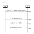
- FIG. 8 is a flowchart showing a method of performing HARQ in a multiple-carrier system.
- a UE receives multiple-carrier information from a BS (step S 810 ).
- the multiple-carrier information is a higher-layer signal such as an RRC message or a part of system information, and may be transmitted by the BS.
- the multiple-carrier information may include the number of UL/DL carriers and/or the number of PHICH groups.
- the UE receives a UL grant from the BS on a PDCCH (step S 820 ).
- the UL grant may include a resource allocation for a PUSCH, a cyclic shift index n DMRS for a DM-RS, and/or a DL carrier index for PHICH transmission.
- the UL grant may include a UL carrier index for the PUSCH, and in this case, a DL carrier for PHICH transmission may be obtained from the UL carrier index.
- the UE transmits UL data on the PUSCH by using the resource allocation of the UL grant (step S 830 ).
- the BS transmits ACK/NACK for the UL data on a PHICH (step S 840 ).
- the PHICH may be identified from the resource used for PUSCH transmission and the cyclic shift index for the DM-RS.
- the DL carrier for PHICH transmission may be obtained implicitly or explicitly by using the UL grant or a higher-layer message.
- a relation between carriers for PUSCH and PHICH transmission is referred to as a mapping relation between the DL carrier and the UL carrier.
- the BS may report the mapping relation between the DL carrier and the UL carrier to the UE by using L1/L2 signaling or broadcast information or other various means.
- PHICH allocation and carrier mapping will be described in detail.
- a required resource amount is defined by the number of PHICH groups, and then a carrier used for PHICH transmission, a PHICH group, and a sequence used in the PHICH group are defined. Symbols to be used in the following description are summarized below.
- N UL carrier The number of UL carriers used for PUSCH transmission
- N DL carrier The number of DL carriers
- N PHICH carrier The number of DL carriers allocated for DL PHICH transmission
- n PHICH carrier A DL carrier index used for PHICH transmission
- n group PHICH A PHICH group index in a corresponding carrier
- n seq PHICH A PHICH sequence index in a corresponding carrier
- k denotes an index of a UL carrier
- k has a value in the range of 0, 1, 2, . . . , (N UL carrier ⁇ 1).
- l denotes an index of a DL carrier capable of PHICH transmission
- l has a value in the range of 0, 1, 2, . . . , (N PHICH carrier ⁇ 1).
- the index k or l may be an index of an absolute frequency domain in which allocation is achieved from a physically low frequency band to a high frequency band, or may be an index of a relative frequency domain determined logically irrespective of the physical frequency band.
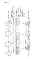
- FIG. 9 shows a method of determining a PHICH resource according to an embodiment of the present invention.
- Logical indices are sequentially assigned to RBs capable of PUSCH transmission from each of UL carriers. For example, if a carrier # 0 has 10 RBs and a carrier # 1 has 5 RBs, logical indices may be assigned from 0 to 14. The logical indices are evenly or unevenly divided according to the number of DL carriers capable of PHICH transmission, and a PHICH resource index (e.g., a PHICH group number) is obtained for each DL carrier in a group of the divided logical indices.
- the RB is only an example of a resource allocation unit of the PUSCH, and thus the resource allocation unit for assigning the logical indices may change variously.
- a PHICH carrier index n PHICH carrier , a PHICH group index n group PHICH , and a PHICH sequence index n seq PHICH are obtained based on a carrier index used for UL transmission, a PUSCH resource for PHICH identification, and a cyclic shift index of a DM-RS.
- Three parameters (i.e., n PHICH carrier , n group PHICH , and n seq PHICH ) for determining a PHICH resource are referred to as a PHICH index.
- a plurality of UL carriers are arranged based on logical indices, and thereafter DL carriers for the PHICH are mapped according to the logical indices. Instead of mapping UL carriers directly to the DL carriers, the UL carriers are re-arranged logically according to RBs, and the PHICH index is obtained according to a re-arranged order.
- the number N DL carrier of DL carriers is equal to the number N PHICH carrier of DL carriers allocated for DL PHICH transmission. Further, resources are allocated to the PUSCH in an RB unit.
- the total number N UL RB — tot of RBs available in UL carriers can be defined by Equation 3 below.
- N UL RB (k) denotes the number of RBs capable of PUSCH transmission on a UL carrier having an index k.
- the number of PHICH groups assigned for each DL carrier can be defined by Equation 4 below.
- N PHICH group ⁇ ( l ) ⁇ ⁇ N g ⁇ ( N RB_tot UL / ( 8 ⁇ N carrier PHICH ) ) ⁇ for ⁇ ⁇ normal ⁇ ⁇ cyclic ⁇ ⁇ prefix 2 ⁇ ⁇ N g ⁇ ( N RB_tot UL / ( 8 ⁇ N carrier PHICH ) ) ⁇ for ⁇ ⁇ extended ⁇ ⁇ cyclic ⁇ ⁇ prefix
- N group carrier (l) denotes the number of PHICH groups of a DL carrier having an index l.
- ⁇ x ⁇ is a ceil function that returns the smallest integer greater than x.
- ⁇ x ⁇ is a floor function that returns the greatest integer less than x.
- N g may be provided by a higher layer signal and used to perform scaling on the number of PHICH groups according to a currently required condition.
- N g may be given as an m-bit value. For example, m may have any one of values 2, 3, and 4.
- N g may be used as a scaling factor when multiple codewords are used in a UL.
- a bandwidth of UL carriers allocated for UL PUSCH transmission may be inconsistent, or a bandwidth of DL carriers allocated for DL PHICH transmission may be inconsistent.
- the value N g applied to each DL carrier allocated for DL PHICH transmission may change. This can be expressed by Equation 5 below.
- N PHICH group ⁇ ( l ) ⁇ ⁇ N g ⁇ ( l ) ⁇ ( N RB_tot UL / ( 8 ⁇ N carrier PHICH ) ) ⁇ for ⁇ ⁇ normal ⁇ ⁇ cyclic ⁇ ⁇ prefix 2 ⁇ ⁇ N g ⁇ ( l ) ⁇ ( N RB_tot UL / ( 8 ⁇ N carrier PHICH ) ) ⁇ for ⁇ ⁇ extended ⁇ ⁇ cyclic ⁇ ⁇ prefix
- N g (l) denotes N g at the DL carrier index l.
- N c denotes the number of codewords transmitted on each UL carrier.
- N g is used for scaling control instead of applying N c .
- Equation 7 the number of codewords transmitted for each UL carrier changes, the number N group PHICH (l) of PHICH groups for the carrier having the index l can be expressed by Equation 7 below.
- N c (l) denotes N, at the DL carrier index l.
- the number of PHICH groups of each DL carrier may be determined based on the total number of resource blocks that can be used in DL carriers and the total number of DL carriers.
- the total number N DL RB — tot of RBs that can be used in the DL carriers can be defined by Equation 8 below.
- N DL RB (m) denotes the number of RBs of a DL carrier having a carrier index m. Equation 8 above implies that N DL RB — tot can be determined according to the total number N DL carrier of DL carriers or the number N PHICH carrier of DL carriers that can be used for PHICH transmission. If N DL carrier is equal to N PHICH carrier , m has a value in the range from 0 to (N PHICH carrier ⁇ 1).
- the number of PHICH groups of the DL carrier having the index l can be defined by Equation 9 below.
- N PHICH group ⁇ ( l ) ⁇ ⁇ N g ⁇ ( N RB_tot DL / ( 8 ⁇ N carrier PHICH ) ) ⁇ for ⁇ ⁇ normal ⁇ ⁇ cyclic ⁇ ⁇ prefix 2 ⁇ ⁇ N g ⁇ ( N RB_tot DL / ( 8 ⁇ N carrier PHICH ) ) ⁇ for ⁇ ⁇ extended ⁇ ⁇ cyclic ⁇ ⁇ prefix
- N g may be provided by a higher-layer signal and used to perform scaling on the number of PHICH groups according to a currently required condition.
- N g may be given as an m-bit value.
- m may have any one of values 2, 3, and 4.
- N g may be used as a scaling factor when multiple codewords are used in a UL.
- a bandwidth of UL carriers may be inconsistent, or a bandwidth of DL carriers may be inconsistent.
- the value N g applied to each DL carrier may change. This can be expressed by Equation 10 below.
- N PHICH group ⁇ ( l ) ⁇ ⁇ N g ⁇ ( l ) ⁇ ( N RB_tot DL / ( 8 ⁇ N carrier PHICH ) ) ⁇ for ⁇ ⁇ normal ⁇ ⁇ cyclic ⁇ ⁇ prefix 2 ⁇ ⁇ N g ⁇ ( l ) ⁇ ( N RB_tot DL / ( 8 ⁇ N carrier PHICH ) ) ⁇ for ⁇ ⁇ extended ⁇ ⁇ cyclic ⁇ ⁇ prefix
- N g (l) denotes N g at the DL carrier index l.
- the number of PHICH groups can be expressed by Equation 11 below.
- N c denotes the number of codewords transmitted on each UL carrier.
- N g is used for scaling control instead of applying N c .
- the number of PHICH groups for each DL carrier can be expressed by Equation 12 below.
- N c (l) denotes N c at the DL carrier index l.
- Equation 9 to Equation 12 above can be re-expressed by Equation 13 below.
- N PHICH group ⁇ ( l ) ⁇ ⁇ N g ⁇ ( N RB_tot DL ⁇ R RB UL / DL / ( 8 ⁇ N carrier PHICH ) ) ⁇ for ⁇ ⁇ normal cyclic ⁇ ⁇ prefix 2 ⁇ ⁇ N g ⁇ ( N RB_tot DL ⁇ R RB UL / DL / ( 8 ⁇ N carrier PHICH ) ) ⁇ for ⁇ ⁇ extended cyclic ⁇ ⁇ prefix [ Equation ⁇ ⁇ 13 ]
- N PHICH group ⁇ ( l ) ⁇ ⁇ N g ⁇ ( l ) ⁇ ( N RB_tot DL ⁇ R RB UL / DL / ( 8 ⁇ N carrier PHICH ) ) ⁇ for ⁇ ⁇ normal cyclic ⁇ ⁇ prefix 2 ⁇ ⁇ N g ⁇ ( l ) ⁇ ( N RB_tot DL
- Equation 13 above is a list of candidate equations capable of calculating the number of PHICH groups by using the RB ratio.
- N g is not used for scaling of a ratio of the total number of RBs that can be used in the UL and the total number of RBs that can be used in the DL, but is used to perform scaling for regulating the total number of PHICH groups. Therefore, the number of possible cases of determining the value N g is decreased, and thus the number of bits of the value N g may be further decreased than that used in the conventional method.
- Equation 9 to Equation 13 above are for defining the number N group PHICH (l) of PHICH groups for each DL carrier.
- three parameters are required, i.e., a DL carrier index n PHICH carrier for PHICH transmission, a PHICH group index n group PHICH in a DL carrier, and a PHICH sequence index n seq PHICH in a PHICH group.
- a BS sends ACK/NACK by configuring the PHICH defined by using the three parameters.
- the UE identifies the PHICH transmitted to the UE by using the three parameters.
- a PHICH indexing method for defining the three parameters is proposed.
- n PHICH carrier is obtained based on a value calculated by adding a sum of the number of available RBs of UL carriers having a lower index than an index k of a UL carrier used for PUSCH transmission to the lowest PRB index of a PUSCH allocated at the UL carrier k used for current PUSCH transmission (this value is referred to as an aggregated PRB index).
- the PHICH carrier index n PHICH carrier is determined by sequentially applying the number of PHICH resources for each DL carrier in an ascending order of a DL carrier index.
- the PHICH group index n group PHICH in the DL carrier of the index n PHICH carrier can be obtained based on a result of subtracting a value obtained by multiplying a PHICH resource allocated for each PHICH carrier by previous DL PHICH carrier indices from the aggregated PRB index and then adding a cyclic shift index of a DM-RS.
- the PHICH sequence index n seq PHICH in the PHICH group can be obtained similarly to a method of obtaining the PHICH group index n group PHICH .
- a PHICH carrier index for a UL carrier having an index k for PUSCH transmission can be determined by any one of equations of Equation 14 below.
- N UL RB (p) denotes the number of RBs of a UL carrier having an index p.
- I lowest — index PRB — RA denotes the lowest PRB index of a PUSCH transmitted on the UL carrier having the index k.
- N UL RB — tot denotes the total number of RBs of UL carriers.
- N PHICH carrier denotes the total number of DL carriers that can be used for PHICH transmission. Since the number of PHICH resources for each DL carrier allocated for PHICH transmission can be expressed in three types, i.e.
- N RB_tot UL N carrier PHICH , ⁇ N RB_tot UL N carrier PHICH ⁇ , ⁇ N RB_tot UL N carrier PHICH ⁇ and Equation 14 above is expressed in three types.
- I PRB_RA lowest_index is a value calculated by adding a sum of the number of available RBs of UL carriers having a lower index than the index k of the UL carrier used for PUSCH transmission to the lowest PRB index of a PUSCH allocated at the UL carrier k used for current PUSCH transmission.
- the PHICH group index n group PHICH in the DL carrier of the index n PHICH carrier can be obtained based on a result of subtracting a value obtained by multiplying a PHICH resource allocated for each PHICH carrier by previous DL PHICH carrier indices from the aggregated PRB index and then adding a cyclic shift index of a DM-RS. This can be expressed by Equation 15 below.
- N PHICH SF denotes a spreading factor used in PHICH modulation
- n seq RS denotes a cyclic shift index of a DM-RS.
- I PHICH is 1 when PUSCH transmission is performed in a subframe 4 or a subframe 9 in a TDD UL/DL configuration 0, and otherwise is 0.
- Table 2 shows a structure of a radio frame that can be configured according to an arrangement of a UL subframe and a DL subframe in a 3GPP LTE TDD system.
- ‘D’ denotes a DL subframe
- ‘U’ denotes a UL subframe
- ‘S’ denotes a special subframe.
- I PHICH is 1 when PUSCH transmission is performed in subframes #4 and #9, and otherwise is 0.
- the PHICH sequence index n seq PHICH in the PHICH group can be obtained by Equation 16 below, similarly to the method of obtaining the PHICH group index n group PHICH .
- a cyclic shift index of a DM-RS used in each codeword transmission can be mapped differently for each codeword transmission.
- the cyclic shift index of the DM-RS for each codeword is denoted by n seq RS (v) (where v is a codeword index).
- n PHICH carrier (v), n group PHICH (v), and n seq PHICH (v) based on the codeword index v can be determined by Equation 17 below.
- n seq RS (v) is a cyclic shift index of a DM-RS having a codeword index v.
- the equations of Equation 17 are identical to those of Equation 14 to Equation 16 except that the codeword index is denoted by v.
- n PHICH carrier (v) uses Equation 17 above, whereas n group PHICH (v) and n seq PHICH (v) may further include a function f(v) for assigning an offset in addition to n seq RS (v).
- ⁇ is a constant, and may be given by a higher-layer signal.
- n group PHICH (v) and n seq PHICH (v) can be expressed by Equation 19 below, by multiplying a function f(v) for assigning scaling by n seq RS (v) for each codeword index v.
- f(v) can be defined variously.
- ⁇ is a constant, and may be given by a higher-layer signal.
- PHICH carriers have the same bandwidth (e.g., the PHICH resource is the same for each PHICH carrier).
- three parameters i.e., n PHICH carrier , n GROUP PHICH , and n seq PHICH ) have different bandwidths for respective carriers will be considered hereinafter.
- N PHICH (l) is defined as the number of PHICH resources in a PHICH carrier having an index l.
- n PHICH carrier is determined by considering N PHICH (l) and I lowest — index PRB — RA , i.e., the lowest PRB index of a PUSCH transmitted on a UL carrier having an index k. More specifically, n PHICH carrier can be determined by considering N PHICH (l) and an aggregated PRB index.
- n PHICH carrier is set to a maximum value r of a PHICH carrier index l in a situation where a value equal to or less than 0 firsts appears while sequentially subtracting N PHICH (l), i.e., the number PHICH resources having the PHICH carrier index l, from the aggregated PRB index
- n PHICH carrier can be obtained by Equation 21 below.
- n group PHICH and n seq PHICH can be obtained based on a result of subtracting a total sum of PHICH resources of previous DL PHICH carriers from an aggregated PRB index and adding a cyclic shift index n seq RS of a DM-RS used in PUSCH transmission. This
- n PHICH carrier , n group PHICH , and n seq PHICH of Equation 21 to Equation 22 use N seq RS (v), i.e., a cyclic shift index of a DM-RS of a codeword index v, and n PHICH carrier (v), n group PHICH (v), and n seq PHICH (v) can be expressed by Equation 23 below.
- ⁇ is a constant, and may be given by a higher-layer signal.
- n group PHICH (v) and n seq PHICH (v) can be expressed by Equation 25 below, by multiplying a function f(v) for assigning scaling by n seq RS (v) for each codeword index v.
- f(v) can be defined variously.
- ⁇ is a constant, and may be given by a higher-layer signal.
- the aforementioned embodiments can be implemented separately or in a combined manner. At least one of the embodiments of determining the number N group PHICH (l) of PHICH groups and an embodiment of determining three parameters n PHICH carrier , n group PHICH and n seq PHICH or three parameters n PHICH carrier (v), n group PHICH (v), and n seq PHICH (v) may be combined.
- mapping relation in which a PHICH carrier and a PUSCH transmission carrier are mapped in a one-to-one or one-to-many manner to each other is predetermined.
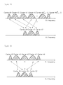
- FIG. 10 shows an example of mapping between a UL carrier and a DL carrier.
- carriers belonging to a link having a greater number of carriers are mapped to carriers of the other link according to an index order.
- the mapping may follow a mapping rule in which indices of carriers belonging to a link having a greater number of carriers are mapped to indices of carriers belonging to a link having a smaller number of carriers by using a modulo operation.
- N min carrier is defined by min(N DL carrier , N UL carrier ) that returns a smaller value between N DL carrier and N UL carrier , and % denotes a modulo operation.
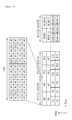
- FIG. 11 shows another example of mapping between a UL carrier and a DL carrier.
- a carrier index is assigned in an ascending order starting from a carrier belonging to the lowest DL/UL frequency band.
- a center carrier is defined as a carrier corresponding to a band to which a center frequency of a system belongs
- the carrier is mapped by using the center carrier as a reference carrier in an order starting from a carrier nearest to the reference carrier. This is a suitable method when the number of carriers of each link is odd.
- the center carrier being used as the reference carrier, the number of carriers belonging to a low frequency band is equal to the number of carriers belonging to a high frequency band.
- the number of DL carriers is 5, and the number of UL carriers is 3.
- the center carrier i.e., reference carrier
- the center carrier is a DL carrier # 2 .
- the center carrier is a UL carrier # 1 .
- the DL carrier # 2 is mapped to the UL carrier # 1 .
- a DL carrier # 1 is mapped to a UL carrier # 0
- a DL carrier # 3 is mapped to a UL carrier # 2 .
- DL carriers # 0 and # 4 are mapped to the UL carrier # 1 , i.e., the center carrier.
- one-to-one mapping is performed by the number of carriers belonging to a link having a smaller number of allocated carriers between the downlink and the uplink. That is, one-to-one mapping is performed by the number of carriers belonging to a link having a smaller number of carriers. Further, the remaining carriers belonging to a link having a greater number of carriers may be mapped to a center carrier of the link having the smaller number of carriers. Alternatively, the remaining carriers belonging to the link having the greater number of carriers can be sequentially mapped starting from a carrier having the smallest carrier index among carrier indices belonging to the link having the smaller number of carriers, in an ascending order of a carrier index. On the contrary, mapping can also be performed starting from a carrier having the greatest carrier index among carrier indices belonging to the link having the smaller number of carriers in the ascending order of the carrier index.
- a ratio R of the number of carriers may be defined for carrier mapping, and this ratio may be used in carrier mapping.
- ceil(x) denotes a smallest integer greater than x
- floor(x) denotes a greatest integer less than x.
- a resource index used for a UL resource and an index of a resource used for the PDCCH may be mapped by being divided for each group according to R DL/UL or R UL/DL .
- Information on the mapping rule may be reported to all UEs in a cell as common information by using a higher-layer signal (e.g., an RRC signal) or an L1/L2 control signal, or may be reported to any UE as UE-specific information.
- the information may be used by a BS and a UE for resource allocation and indexing for a control channel of a UL carrier and a DL carrier.
- mapping can be configured between the carrier and the DL carrier by using a BS scheduler and/or the higher layer signal (e.g., RRC).
- RRC higher layer signal
- a mapping relation configured between the UL carrier and the DL carrier can be applied when the DL carrier for DL PHICH transmission is configured for data transmission on any UL carrier.
- FIG. 12 shows a method of determining a PHICH resource according to an embodiment of the present invention.
- Logical indices are sequentially assigned to RBs capable of PUSCH transmission from each of UL carriers. For example, if a carrier # 0 has 10 RBs and a carrier # 1 has 5 RBs, logical indices may be assigned from 0 to 14. The logical indices are divided according to UL carriers corresponding to respective PHICH carriers, and a PHICH resource (e.g., the number of PHICH groups) is obtained for each PHICH carrier in a group of the divided logical indices.
- a PHICH resource e.g., the number of PHICH groups
- a PHICH group index n group PHICH (l) for a PHICH carrier having an index l and a PHICH sequence index n seq PHICH (l) for the PHICH carrier having the index l are obtained based on a PUSCH resource for PHICH indication and a cyclic shift index of a DM-RS.
- the two parameters, i.e., n group PHICH (l) and n seq PHICH (l), for determining the PHICH resource are referred to as a PHICH index.
- carriers capable of PHICH transmission may respectively correspond to UL carriers to be used for PUSCH transmission.
- the number of PHICH groups can be obtained based on the total number of PHICH resources required for corresponding PUSCH transmission carriers.
- N UL carrier (l) The number of UL carriers corresponding to a PHICH carrier having an index l
- c UL (l) A logical index of the UL carrier corresponding to the PHICH carrier having the index l.
- c UL (l) has a value in the range of 0 to N UL carrier (l) ⁇ 1
- N RB (c UL (l)) The number of RBs capable of PUSCH transmission of a UL carrier having an index c UL (l) or the number of available RBs of a UE for the UL carrier having the index c UL (l)
- N tot RB (l) The total number of RBs for UL carriers corresponding to the PHICH carrier having the index l.
- N tot RB (l) is the total number of PHICH resources supportable by the PHICH carrier having the index l, and can be obtained by Equation 27 below.
- N tot RB (l) is only an example, and thus can change variously according to allocation or definition of the RB.
- a method of obtaining the number N group PHICH (l) of PHICH groups in the DL carrier having the index l will be described by using the symbols defined above.
- the number N group PHICH (l) of PHICH groups in the DL carrier having the index l can be obtained by Equation 28 below by using N tot RB (l).
- N PHICH group ⁇ ( l ) ⁇ ⁇ ⁇ N g ⁇ ( N RB tot ⁇ ( l ) ⁇ / ⁇ 8 ) ⁇ ⁇ for ⁇ ⁇ normal ⁇ ⁇ cyclic ⁇ ⁇ prefix ⁇ 2 ⁇ ⁇ N g ⁇ ( N RB tot ⁇ ( l ) ⁇ / ⁇ 8 ) ⁇ ⁇ for ⁇ ⁇ extended ⁇ ⁇ cyclic ⁇ ⁇ prefix [ Equation ⁇ ⁇ 28 ]
- N g may be provided by a higher-layer signal and used to perform scaling on the number of PHICH groups according to a condition.
- N g may be given as an m-bit value.
- m may have any one of values 2, 3, and 4.
- backward compatibility with a 3GPP LTE system can be supported.
- N g (l) denotes N g in the DL carrier having the index l
- N g (l) of PHICH groups in the DL'carrier having the index l can be obtained by Equation 29 below.
- N PHICH group ⁇ ( l ) ⁇ ⁇ ⁇ N g ⁇ ( l ) ⁇ ( N RB tot ⁇ ( l ) ⁇ / ⁇ 8 ) ⁇ ⁇ for ⁇ ⁇ normal ⁇ ⁇ cyclic ⁇ ⁇ prefix ⁇ 2 ⁇ ⁇ N g ⁇ ( l ) ⁇ ( N RB tot ⁇ ( l ) ⁇ / ⁇ 8 ) ⁇ ⁇ for ⁇ ⁇ extended ⁇ ⁇ cyclic ⁇ ⁇ prefix [ Equation ⁇ ⁇ 29 ]
- N g (l) may be reported by the BS to the UE by using a primary carrier as an RRC message or a part of system information.
- the primary carrier is a DL carrier for transmitting primary control information.
- N group PHICH (l) when multiple-codeword transmission is possible on UL carriers, N group PHICH (l) can be expressed by Equation 30 below, where N C denotes the number of codewords.
- scaling of N g may be controlled instead of N C .
- the number of PHICH groups can be regulated by using a scaling factor N g (l) based on a value of the DL carrier index l instead of N g .
- N g (l) may be reported by the BS to the UE on the primary carrier.
- the number of PHICH groups for each DL carrier can be obtained by Equation 31 below, where N C (l) denotes the number of codewords in the carrier having the index l.
- the number of PHICH groups can be regulated by using a scaling factor N g (l) based on a value of the DL carrier index l instead of N g .
- N g (l) may be reported by the BS to the UE on the primary carrier.
- the number n group PHICH (l) of PHICH groups in the DL carrier having the index l is essential information that must be known to the UE not only for PHICH reception but also for PDCCH monitoring.
- Multiple-carrier information that must be obtained by the UE from the BS in the process of initial network entry includes the number of allocated UL carriers, a bandwidth for each carrier, and a center frequency for each carrier.
- the multiple-carrier information may be reported by the BS to the UE by using a part of system information, a synchronization signal, and/or an RRC message.
- the multiple-carrier information may be transmitted on a specific carrier (referred to as a reference carrier or a primary carrier). After obtaining the multiple-carrier information from the reference carrier in an initial network entry process or a handover process, the UE may attempt to access to another carrier.
- the number of PHICH groups is defined based on the total number of RBs that can be used by available DL carriers.
- N DL RB — tot i.e., the total number, of RBs that can be used in a DL, can be obtained by using any one of equations of Equation 32 below.
- N PHICH carrier denotes the total number of DL carriers that can be used for PHICH transmission
- N DL carrier denotes the total number of DL carriers
- m denotes a relative index of a DL carrier
- m ref denotes an index of a DL reference carrier
- N DL RB (m) denotes the number of available RBs in a DL carrier.
- N DL RB — tot (l) i.e., the total number of RBs for the DL carrier having the index l
- N RB DL — tot ( l ) N RB DL ( l )
- N RB DL — tot ( l ) N RB — tot DL
- N RB DL — tot ( l ) N RB — tot DL /N carrier DL
- N RB DL — tot ( l ) N RB — tot DL /N carrier PHICH
- N group PHICH (l) i.e., the number of PHICH groups for the DL carrier having the index l can be obtained by Equation 34 below.
- N PHICH group ⁇ ( l ) ⁇ ⁇ N g ⁇ ( N RB DL_tot ⁇ ( l ) / 8 ) ⁇ for ⁇ ⁇ normal ⁇ ⁇ cyclic ⁇ ⁇ prefix 2 ⁇ ⁇ N g ⁇ ( N RB DL_tot ⁇ ( l ) / 8 ) ⁇ for ⁇ ⁇ extended ⁇ ⁇ cyclic ⁇ ⁇ prefix [ Equation ⁇ ⁇ 34 ]
- N g may be provided by a higher-layer signal and used to perform scaling on the number of PHICH groups according to a condition.
- N g may be given as an m-bit value.
- m may have any one of values 2, 3, 4, and 5.
- backward compatibility with a 3GPP LTE system can be supported.
- N g (l) denotes N g in the DL carrier having the index l
- N g (l) of PHICH groups in the DL carrier having the index l can be obtained by Equation 35 below.
- N PHICH group ⁇ ( l ) ⁇ ⁇ N g ⁇ ( l ) ⁇ ( N RB DL_tot ⁇ ( l ) / 8 ) ⁇ for ⁇ ⁇ normal ⁇ ⁇ cyclic ⁇ ⁇ prefix 2 ⁇ ⁇ N g ⁇ ( l ) ⁇ ( N RB DL_tot ⁇ ( l ) / 8 ) ⁇ for ⁇ ⁇ extended ⁇ ⁇ cyclic ⁇ ⁇ prefix [ Equation ⁇ ⁇ 35 ]
- N g (l) may be provided by RRC signaling of a primary carrier or may be signaled by using an RRC signal transmitted in a carrier-specific manner on a DL carrier for PHICH transmission.
- N group PHICH (l) when multiple-codeword transmission is possible on UL carriers, N group PHICH (l) can be expressed by Equation 36 below, where N C denotes the number of codewords.
- scaling of N g may be controlled instead of N C .
- the number of PHICH groups can be regulated by using a scaling factor N g (l) based on a value of a DL carrier index l instead of N g .
- N g (l) may be reported by the BS to the UE on the primary carrier.
- N group PHICH (l) of PHICH groups for the DL carrier having the index l can be obtained by Equation 37 below, where N C (l) denotes the number of codewords in the carrier having the index l.
- the number of PHICH groups can be regulated by using a scaling factor N g (l) based on a value of a DL carrier index l instead of N g .
- N g (l) may be reported by the BS to the UE on the primary carrier.
- N g (l) may be reported by the BS to the UE on the primary carrier.
- n group PHICH (l) is used to allocate a logical index by considering an index order of UL carriers corresponding to the PHICH carriers, and is obtained based on a value calculated by adding a sum of the number of available RBs of UL carriers having a lower index than an index c UL (l) of a UL carrier used for PUSCH transmission to the lowest PRB index of a PUSCH allocated to the UL carrier c UL (l) used for current PUSCH transmission (this is referred to as a locally aggregated PRB index).
- n seq PHICH (l) can be obtained similarly to the method of obtaining n group PHICH (l) described above.
- I PRB_RA lowest_index is a value calculated by adding a sum of the number of available RBs of UL carriers having a lower index than an index c UL (l) of a UL carrier used for PUSCH transmission to the lowest PRB index I lowest — index PRB — RA of a PUSCH allocated to the UL carrier c UL (l) used for current PUSCH transmission.
- n group PHICH (l) can be obtained based on a result of adding a cyclic shift index n seq RS of a DM-RS to the locally aggregated PRB index.
- n group PHICH (l) and n seq PHICH (l) can be obtained by Equation 38 below.
- a cyclic shift index of a DM-RS used in each codeword transmission can be mapped differently for each codeword transmission.
- the cyclic shift index of the DM-RS for each codeword is denoted by n seq RS (v) (where v is a codeword index).
- n group PHICH (l,v) and n seq PHICH (l,v) based on the codeword index v can be determined by Equation 39 below.
- n group PHICH (l,v) and n seq PHICH (l,v) may further include a function f(v) for assigning an offset in addition to n seq RS (v).
- ⁇ is a constant, and may be given by a higher-layer signal.
- ⁇ is an offset value for supporting backward compatibility, and may be given by the higher-layer signal.
- n group PHICH (l,v) and n seq PHICH (l,v) can be expressed by Equation 41 below, by multiplying a function f(v) for assigning scaling by n seq RS (v) for each codeword index v.
- the scaling function f(v) can be defined variously.
- ⁇ is a constant, and may be given by a higher-layer signal.
- ⁇ is an offset value for supporting backward compatibility, and may be given by the higher-layer signal.
- the aforementioned embodiments can be implemented separately or in a combined manner. At least one of the embodiments of determining the number N group PHICH (l) of PHICH groups and an embodiment of determining three parameters n PHICH carrier (l), n group PHICH (l), and n seq PHICH (l) or three parameters n PHICH carrier (l,v), n group PHICH (l,v), and n seq PHICH (l,v) may be combined.
- any one of embodiments of obtaining the number of PHICH groups and PHICH indices n PHICH carrier , n group PHICH , and n seq PHICH when there is no mapping relation between a UL carrier and a DL carrier and any one of embodiments of obtaining the number of PHICH groups and PHICH indices n group PHICH and n seq PHICH when there is a mapping relation between the UL carrier and the DL carrier may be combined.
- a DL grant is transmitted to a UE on a PDCCH, and DL data is transmitted on a PDSCH indicated by the PDCCH.
- the UE transmits ACK/NACK on a PUCCH in an (n+4) th subframe.
- the ACK/NACK is transmitted using a PUCCH format 1a/1b.
- Equation 42 a PUCCH format 1/1a/1b is expressed mathematically by Equation 42 below.
- N PUCCH SF 4 in case of a normal PUCCH format 1/1a/1b.
- a resource for transmission of the PUCCH format 1/1a/1b is determined by a resource index n (l) PUCCH , a CS amount ⁇ (n s , l) of a basis sequence, and an orthogonal sequence index n OC (n s ).
- the CS amount ⁇ (n s , l) of the basis sequence and the orthogonal sequence index n OC (n s ) are determined by Equation 43 below.
- a resource index n (l) PUCCH for HARQ ACK/NACK is obtained as shown in Table 3 below, which is disclosed in the section 10.1 of 3GPP TS 36.213 V8.3.0 (2008-05).
- n PUCCH (1) n CCE + N PUCCH (1) , where n CCE is the number of the first CCE used for transmission of the corresponding DCI assignment and N PUCCH (1) is configured by higher layers.
- n PUCCH (1) is configured by higher layers.
- ACK/NACK is sent in an (n+4) th subframe with respect to DL data transmitted in an n th subframe which is dynamically scheduled.
- n PRB is determined by n (l) PUCCH .
- Equation 44 the physical RB index n PRB is determined by Equation 44 below.
- the aforementioned PUCCH format 1a/1b is configured based on the last CCE index of a PDCCH, and does not consider multiple carriers.
- PDSCH/PDCCH are transmitted on a plurality of DL carriers
- PUCCH/PUSCH are transmitted on a plurality of UL carriers
- a method of allocating a PUCCH resource is proposed as follows.
- the DL carriers and the UL carriers can be mapped in a one-to-one or one-to-many manner. For example, if an index i of DL carriers is constructed in an order from a low frequency to a high frequency and an index j of UL carriers is also configured likewise, then DL carriers and UL carriers having the same index can be mapped. Alternatively, it is also possible to map an index i sorted in an ascending order and an index k sorted in a descending order. Alternatively, symmetrical mapping is also possible with a center frequency being located in the center.
- the DL carriers and the UL carriers may be mapped by using a cell-specific message or a UE-specific RRC signal or PDCCH signaling.
- a PUCCH resource can be determined based on the lowest CCE index used in a PDCCH indicating PDSCH transmission of the DL carriers mapped using the aforementioned method.
- a single logical basis CCE stream is configured by combining a CCE index for each DL carrier for PDCCH transmission in an order of DL carriers with respect to all carriers capable of PDSCH transmission, and the single logical index is allocated by using a DL carrier index for PDSCH transmission on the basis CCE stream and a CCE index in the DL carrier.
- the logical index is evenly or unevenly allocated on the basis CCE stream with respect to UL carriers capable of transmission ACK/NACK on a PUCCH or a PUSCH.
- some carriers may be selected and grouped from a plurality of UL carriers, and a PUCCH resource may be allocated for PDSCH transmission with respect to an index of UL carriers in a group.
- one group of all logical CCE streams may be configured by summing up CCE indices with respect to all DL carriers capable of PDSCH transmission, and an index on the all CCE streams may be allocated by using a carrier index for PDSCH transmission on all logical CCE streams and a CCE index in the carrier.
- a PUCCH resource may be allocated using CCE index-based channel allocation on the PUSCH or PUSCH channel allocation based on a UL grant.
- the plurality of ACK/NACK signals are transmitted by using: (1) a plurality of existing PUCCHs; (2) a single PUCCH with a new format; or (3) a PUSCH.
- the ACK/NACK may be transmitted by puncturing frequency resources of OFDM symbols located near a DM-RS, or may be transmitted by using time-first-mapping, or may be transmitted in the same method as typical PUSCH, transmission by using a modulation and coding scheme of a shared channel.
- Channel allocation/multiplexing and channel indexing for UL channels such as a PUCCH for carrying a UL control signal (e.g., ACK/NACK, a channel quality indicator (CQI), a precoding matrix index (PMI), a rank indication (RI), etc.) and a scheduling request channel may be configured or signaled by using a higher-layer signal.
- a UL carrier used for transmission of a UL control channel and a DL carrier in association therewith may be reported by the BS to the UE by using the higher-layer signal or L1/L2 control signaling.
- 3GPP LTE reports a size of a control region for PDCCH transmission, i.e., the number of OFDM symbols occupied by the control region, on a PCFICH.
- a maximum size of the control region is 3 OFDM symbols at present.
- the PHICH When the size of the control region is 4, if the PHICH is limited to 3 OFDM symbols as in the conventional method, it may result in system performance deterioration. This is because the increasing of power of the PHICH to improve PHICH reliability may result in a difference in transmit power for each OFDM symbol of a PDCCH, which may lead to deterioration of PDCCH detection performance. Therefore, a new PHICH duration needs to be set when the control region occupies 4 OFDM symbols.
- a PHICH duration transmitted on a BCH may have a value corresponding to 1 or 4 OFDM symbols. In another example, if the value transmitted on the PCFICH corresponds to 4 OFDM symbols, the PHICH duration transmitted on the BCH may have only a value corresponding to 4 OFDM symbols. In another example, if the value transmitted on the PCFICH corresponds to 4 OFDM symbols, the PHICH duration transmitted on the BCH may have a value corresponding to 3 OFDM symbols. In another example, if the value transmitted on the PCFICH corresponds to 4 OFDM symbols, the PHICH duration may be Set according to a condition such as a system bandwidth or the like.
- FIG. 13 shows indexing of a PHICH resource when a control region occupies 4 OFDM symbols.
- the control region consists of 12 subcarriers and 4 OFDM symbols.
- REGs resource element groups
- indexing is first achieved on each REG in a time axis and then indexing is achieved on the REG in a frequency axis.
- the REG includes 4 contiguous resource elements (REs).
- “RS” indicated in the RE denotes a reference signal, and one REG is denoted by the same number (i.e., # 0 , # 1 , # 2 , . . . ).
- a mini CCE block consists of 10 REGs.
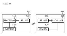
- FIG. 14 is a block diagram showing a wireless communication system for implementing an embodiment of the present invention.
- a BS 500 includes a processor 510 , a memory 530 , and a radio frequency (RF) unit 520 .
- the processor 510 supports HARQ, configures a PHICH, and sends ACK/NACK on the configured PHICH.
- the processor 510 can implement procedures, methods, and functions performed by the BS in the aforementioned embodiments.
- the memory 530 is coupled to the processor 510 , and stores a variety of information for driving the processor 510 .
- the RF unit 520 is coupled to the processor 510 , and transmits and/or receives a radio signal.
- a UE 600 includes a processor 610 , a memory 620 , and an RF unit 630 .
- the processor 610 supports HARQ, sends UL data, and determines a PHICH index for identifying a PHICH.
- the processor 610 can implement procedures, methods, and functions performed by the UE in the aforementioned embodiments.
- the memory 620 is coupled to the processor 610 , and stores a variety of information for driving the processor 610 .
- the RF unit 630 is coupled to the processor 610 , and transmits and/or receives a radio signal.
- the processors 510 and 610 may include an application-specific integrated circuit (ASIC), a separate chipset, a logic circuit, and/or a data processing unit.
- the memories 520 and 620 may include a read-only memory (ROM), a random access memory (RAM), a flash memory, a memory card, a storage medium, and/or other equivalent storage devices.
- the RF units 530 and 630 may include a base-band circuit for processing a radio signal.
- the aforementioned methods can be implemented with a module (i.e., process, function, etc.) for performing the aforementioned functions.
- the module may be stored in the memories 520 and 620 and may be performed by the processors 510 and 610 .
- the memories 520 and 620 may be located inside or outside the processors 510 and 610 , and may be coupled to the processors 510 and 610 by using various well-known means.
Landscapes
- Engineering & Computer Science (AREA)
- Computer Networks & Wireless Communication (AREA)
- Signal Processing (AREA)
- Mobile Radio Communication Systems (AREA)
- Detection And Prevention Of Errors In Transmission (AREA)
Abstract
Description
n PHICH group=(l PRB
n PHICH seq=(└l PRB
| TABLE 1 | |||
| Orthogonal sequence | |||
| Sequence index | Normal cyclic prefix | Extended cyclic prefix | ||
| nPHICH seq | NSF PHICH = 4 | NSF PHICH = 2 | ||
| 0 | [+l +l +l +l] | [+l +l] | ||
| 1 | [+l −l +l −l] | [+l −l] | ||
| 2 | [+l +l −l −l] | [+j +j] | ||
| 3 | [+l −l −l +l] | [+j −j] | ||
| 4 | [+j +j +j +j] | — | ||
| 5 | [+j −j +j −j] | — | ||
| 6 | [+j +j −j −j] | — | ||
| 7 | [+j −j −j +j] | — | ||
and
is a value calculated by adding a sum of the number of available RBs of UL carriers having a lower index than the index k of the UL carrier used for PUSCH transmission to the lowest PRB index of a PUSCH allocated at the UL carrier k used for current PUSCH transmission.
| TABLE 2 | |
| UL-DL | |
| configuration |
| 0 | 1 | 2 | 3 | 4 | 5 | 6 | 7 | 8 | 9 | |
| 0 | D | S | U | U | U | D | S | U | U | U |
| 1 | D | S | U | U | D | D | S | U | U | D |
| 2 | D | S | U | D | D | D | S | U | D | D |
| 3 | D | S | U | U | U | D | D | D | D | D |
| 4 | D | S | U | U | D | D | D | D | D | D |
| 5 | D | S | U | D | D | D | D | D | D | D |
| 6 | D | S | U | U | U | D | S | U | U | D |
in an ascending order starting from the lowest value of the PHICH carrier index l. That is, by calculating
while sequentially increasing the index l, r is set to the
ngroup PHICH and nseq PHICH can be obtained based on a result of subtracting a total sum of PHICH resources of previous DL PHICH carriers from an aggregated PRB index and adding a cyclic shift index nseq RS of a DM-RS used in PUSCH transmission. This can be expressed by Equation 22 below.
In another embodiment, nPHICH carrier(v) uses Equation 23 above, whereas ngroup PHICH(v) and nseq PHICH(v) may further include a function f(v) for assigning an offset in addition to nseq RS(v). For example, the function may be f(v)=v or f(v)=α·v. Herein, α is a constant, and may be given by a higher-layer signal. When using the offset function f(v), ngroup PHICH(v) and nseq PHICH(v) can be expressed by Equation 24 below.
j=i%N carrier min or j=i%N carrier UL [Equation 26]
N RB DL
N RB DL
N RB DL
N RB DL
Ngroup PHICH(l), i.e., the number of PHICH groups for the DL carrier having the index l can be obtained by Equation 34 below.
is a value calculated by adding a sum of the number of available RBs of UL carriers having a lower index than an index cUL(l) of a UL carrier used for PUSCH transmission to the lowest PRB index Ilowest
| TABLE 3 |
| for a dynamically scheduled PDSCH indicated by the detection of a |
| corresponding PDCCH with DCI format 1A/1/2 in subframe n − 4, the |
| UE shall use nPUCCH (1) = nCCE + NPUCCH (1), where nCCE is the number of |
| the first CCE used for transmission of the corresponding DCI assignment |
| and NPUCCH (1) is configured by higher layers. |
| for a semi-persistently scheduled PDSCH transmission and where there |
| is not a corresponding DCI detected in subframe n − 4, the value of |
| nPUCCH (1) is configured by higher layers. |
Claims (4)
Priority Applications (1)
| Application Number | Priority Date | Filing Date | Title |
|---|---|---|---|
| US13/057,704 US8553529B2 (en) | 2008-08-07 | 2009-08-07 | Method and apparatus for performing a HARQ operation in a multi-carrier system |
Applications Claiming Priority (5)
| Application Number | Priority Date | Filing Date | Title |
|---|---|---|---|
| US8680408P | 2008-08-07 | 2008-08-07 | |
| US9022908P | 2008-08-19 | 2008-08-19 | |
| US15791209P | 2009-03-06 | 2009-03-06 | |
| US13/057,704 US8553529B2 (en) | 2008-08-07 | 2009-08-07 | Method and apparatus for performing a HARQ operation in a multi-carrier system |
| PCT/KR2009/004429 WO2010016750A2 (en) | 2008-08-07 | 2009-08-07 | Method and apparatus for performing a harq operation in a multi-carrier system |
Publications (2)
| Publication Number | Publication Date |
|---|---|
| US20110305134A1 US20110305134A1 (en) | 2011-12-15 |
| US8553529B2 true US8553529B2 (en) | 2013-10-08 |
Family
ID=41664113
Family Applications (1)
| Application Number | Title | Priority Date | Filing Date |
|---|---|---|---|
| US13/057,704 Expired - Fee Related US8553529B2 (en) | 2008-08-07 | 2009-08-07 | Method and apparatus for performing a HARQ operation in a multi-carrier system |
Country Status (2)
| Country | Link |
|---|---|
| US (1) | US8553529B2 (en) |
| WO (1) | WO2010016750A2 (en) |
Cited By (2)
| Publication number | Priority date | Publication date | Assignee | Title |
|---|---|---|---|---|
| US20120008585A1 (en) * | 2009-03-29 | 2012-01-12 | Yeong Hyeon Kwon | Method for transmitting control information in wireless communication system and apparatus therefor |
| US20160277155A1 (en) * | 2015-03-17 | 2016-09-22 | Nokia Technologies Oy | Efficient resource allocation for acknowledgement/non-acknowledgement physical uplink shared channel and periodic channel state information physical uplink shared channel |
Families Citing this family (26)
| Publication number | Priority date | Publication date | Assignee | Title |
|---|---|---|---|---|
| BRPI0917452B1 (en) | 2008-08-08 | 2020-11-24 | Sun Patent Trust | radio communication base station apparatus, radio communication terminal apparatus, channel designation method and response signal extraction method |
| KR101089838B1 (en) * | 2008-08-13 | 2011-12-05 | 한국전자통신연구원 | Communication system using carrier aggregation and base stations and terminals belonging to the communication system |
| KR101542384B1 (en) | 2008-11-24 | 2015-08-07 | 엘지전자 주식회사 | PMI selection method for non-adaptive HARQ in wireless communication systems supporting multiple antennas |
| KR101632440B1 (en) | 2008-12-03 | 2016-06-22 | 엘지전자 주식회사 | Method of performing harq for relay station |
| US20100172308A1 (en) * | 2009-01-07 | 2010-07-08 | Samsung Electronics Co., Ltd. | System and method for downlink physical indicator channel mapping with asymmetric carrier aggregation |
| KR101713101B1 (en) * | 2009-03-12 | 2017-03-07 | 인터디지탈 패튼 홀딩스, 인크 | Method and apparatus for selecting and reselecting an uplink primary carrier |
| US8634358B2 (en) * | 2009-04-23 | 2014-01-21 | Qualcomm Incorporated | Method and apparatus for multicarrier control in a wireless communication system |
| CN102804663A (en) * | 2009-06-26 | 2012-11-28 | 诺基亚西门子通信公司 | Apparatus, method and article of manufacture for determining an uplink harq resource |
| KR20110011517A (en) * | 2009-07-28 | 2011-02-08 | 엘지전자 주식회사 | Method and apparatus for performing carrier management procedure in multicarrier-enabled broadband wireless communication system |
| EP3833090B1 (en) | 2009-09-25 | 2023-08-23 | BlackBerry Limited | Multi-carrier network operation |
| WO2011038252A2 (en) | 2009-09-25 | 2011-03-31 | Fong, Mo-Han | System and method for multi-carrier network operation |
| CN102907152B (en) | 2009-09-25 | 2016-08-17 | 黑莓有限公司 | System and method for multi-carrier network operation |
| US20130016841A1 (en) | 2009-09-25 | 2013-01-17 | Mo-Han Fong | System and Method for Multi-Carrier Network Operation |
| KR101730656B1 (en) * | 2009-11-23 | 2017-05-12 | 엘지전자 주식회사 | Method and apparatus of performing contention based uplink transmission in wireless communication system |
| KR101701308B1 (en) * | 2010-01-12 | 2017-02-02 | 주식회사 팬택 | Method and apparatus for transmitting and receiving carrier segment information |
| EP2526708A4 (en) * | 2010-01-18 | 2017-03-29 | Telefonaktiebolaget LM Ericsson (publ) | Method and arrangement in a wireless communication network |
| US8824387B2 (en) * | 2010-03-19 | 2014-09-02 | Qualcomm Incorporated | Resource mapping for multicarrier operation |
| EP2561717A4 (en) * | 2010-04-22 | 2015-07-15 | Sharp Kk | TELECOMMUNICATION METHOD AND SYSTEM FOR ALLOCATION OF PHYSICAL UPLINK CONTROL TRACK RESOURCES, AND BASE STATION, SUBSCRIBER INSTALLATION AND CORRESPONDING INTEGRATED CIRCUIT |
| US20120082079A1 (en) * | 2010-10-04 | 2012-04-05 | Qualcomm Incorporated | Discontinuous transmission (dtx) signaling in uplink data channel |
| US8699621B2 (en) * | 2010-10-04 | 2014-04-15 | Nec Laboratories America, Inc. | Precoding selection for retransmission in uplink MIMO hybrid ARQ |
| CN102457854B (en) * | 2010-10-14 | 2015-06-03 | 华为技术有限公司 | Method, device and system for solving channel conflict |
| CN103314609B (en) * | 2011-01-12 | 2017-02-08 | 诺基亚通信公司 | Method and apparatus for allocating radio resources in cellular communications network |
| CN104272635B (en) | 2012-03-05 | 2021-07-13 | 三星电子株式会社 | Transmission of Hybrid Automatic Repeat Request-Reply Signals in Response to Detection of Control Channel Types in the Case of Multiple Control Channel Types |
| US9641271B2 (en) * | 2013-01-31 | 2017-05-02 | Telefonaktiebolaget Lm Ericsson (Publ) | TDM-based resource partition between two radio base stations |
| US11140749B2 (en) * | 2016-12-13 | 2021-10-05 | Apple Inc. | User equipment (UE), generation node-B (GNB) and methods for signaling of control information for pre-coding |
| US12074708B2 (en) * | 2020-06-19 | 2024-08-27 | Qualcomm Incorporated | Group feedback for multicast communications |
Citations (3)
| Publication number | Priority date | Publication date | Assignee | Title |
|---|---|---|---|---|
| US20090196240A1 (en) * | 2008-02-04 | 2009-08-06 | Nokia Siemens Networks Oy | Method, apparatus and computer program to map a cyclic shift to a channel index |
| US20090245187A1 (en) * | 2008-03-25 | 2009-10-01 | Young-Han Nam | Downlink phich mapping and channelization |
| US20100322324A1 (en) * | 2008-02-04 | 2010-12-23 | Nokia Corporation | Mapping phich resources |
-
2009
- 2009-08-07 US US13/057,704 patent/US8553529B2/en not_active Expired - Fee Related
- 2009-08-07 WO PCT/KR2009/004429 patent/WO2010016750A2/en not_active Ceased
Patent Citations (4)
| Publication number | Priority date | Publication date | Assignee | Title |
|---|---|---|---|---|
| US20090196240A1 (en) * | 2008-02-04 | 2009-08-06 | Nokia Siemens Networks Oy | Method, apparatus and computer program to map a cyclic shift to a channel index |
| US20100322324A1 (en) * | 2008-02-04 | 2010-12-23 | Nokia Corporation | Mapping phich resources |
| US20090245187A1 (en) * | 2008-03-25 | 2009-10-01 | Young-Han Nam | Downlink phich mapping and channelization |
| US8265021B2 (en) * | 2008-03-25 | 2012-09-11 | Samsung Electronics Co., Ltd. | Downlink phich mapping and channelization |
Non-Patent Citations (2)
| Title |
|---|
| 3GPP TS 36.213 v8.2.0, 'E-UTRA Physical layer procedures', Mar. 2008 See pp. 28-29. |
| NEC Group, 'Downlink ACK/NACK signaling for E-UTRA', TSG-RAN WG1#52 R1-074716, Nov. 5, 2007 See p. 1, fig. 1. |
Cited By (12)
| Publication number | Priority date | Publication date | Assignee | Title |
|---|---|---|---|---|
| US20120008585A1 (en) * | 2009-03-29 | 2012-01-12 | Yeong Hyeon Kwon | Method for transmitting control information in wireless communication system and apparatus therefor |
| US9401779B2 (en) * | 2009-03-29 | 2016-07-26 | Lg Electronics Inc. | Method for transmitting control information in wireless communication system and apparatus therefor |
| US9401780B2 (en) | 2009-03-29 | 2016-07-26 | Lg Electronics Inc. | Method for transmitting control information in wireless communication system and apparatus therefor |
| US9525518B2 (en) | 2009-03-29 | 2016-12-20 | Lg Electronics Inc. | Method for transmitting control information in wireless communication system and apparatus therefor |
| US9742545B2 (en) | 2009-03-29 | 2017-08-22 | Lg Electronics Inc. | Method for transmitting control information in wireless communication system and apparatus therefor |
| US10063360B2 (en) | 2009-03-29 | 2018-08-28 | Lg Electronics Inc. | Method for transmitting control information in wireless communication system and apparatus therefor |
| US10211963B2 (en) | 2009-03-29 | 2019-02-19 | Lg Electronics Inc. | Method for transmitting control information in wireless communication system and apparatus therefor |
| US10505693B2 (en) | 2009-03-29 | 2019-12-10 | Lg Electronics Inc. | Method for transmitting control information in wireless communication system and apparatus therefor |
| US10855431B2 (en) | 2009-03-29 | 2020-12-01 | Lg Electronics Inc. | Method for transmitting control information in wireless communication system and apparatus therefor |
| US10911206B2 (en) | 2009-03-29 | 2021-02-02 | Lg Electronics Inc. | Method for transmitting control information in wireless communication system and apparatus therefor |
| US11546118B2 (en) | 2009-03-29 | 2023-01-03 | Lg Electronics Inc. | Method for transmitting control information in wireless communication system and apparatus therefor |
| US20160277155A1 (en) * | 2015-03-17 | 2016-09-22 | Nokia Technologies Oy | Efficient resource allocation for acknowledgement/non-acknowledgement physical uplink shared channel and periodic channel state information physical uplink shared channel |
Also Published As
| Publication number | Publication date |
|---|---|
| WO2010016750A3 (en) | 2010-05-27 |
| US20110305134A1 (en) | 2011-12-15 |
| WO2010016750A2 (en) | 2010-02-11 |
Similar Documents
| Publication | Publication Date | Title |
|---|---|---|
| US8553529B2 (en) | Method and apparatus for performing a HARQ operation in a multi-carrier system | |
| JP5643831B2 (en) | Reception confirmation transmission method and apparatus in wireless communication system | |
| EP2352249B1 (en) | Method and apparatus for performing harq process in wireless communication system | |
| US8861463B2 (en) | Apparatus and method for performing an uplink HARQ in a wireless communication system | |
| US8767528B2 (en) | Method and apparatus for receiving reception acknowledgement in wireless communication system | |
| EP2514129B1 (en) | Apparatus and method of transmitting reception acknowledgement in wireless communication system | |
| US9949264B2 (en) | Method and apparatus for transmitting a reference signal in a wireless communication system | |
| US9100158B2 (en) | Method and apparatus for transmitting multiple reception confirmations in time division duplex system | |
| US9276721B2 (en) | Decoding data in group search space based on group control information | |
| EP2600555B1 (en) | Method and apparatus for transmitting uplink control information in a wireless communication system | |
| US9860023B2 (en) | Method and device for receiving ACK/NACK in wireless communication system | |
| CN105580289B (en) | Method and apparatus for being decoded in a wireless communication system by terminal-pair down link control information | |
| KR101710205B1 (en) | Method and apparatus for communication in multiple carrier system | |
| KR20100014118A (en) | Method and apparatus of transmitting data in multiple carrier system | |
| EP2584730B1 (en) | Method and device for transmitting acknowledgement in wireless communication system | |
| CN105594149A (en) | Method whereby terminal transmits ACK/NACK in wireless communication system, and device therefor | |
| CN105612708B (en) | Method and apparatus for transmitting ACK/NACK by terminal in wireless communication system | |
| KR20100117045A (en) | Method and apparatus of performing harq in multiple carrier system |
Legal Events
| Date | Code | Title | Description |
|---|---|---|---|
| AS | Assignment |
Owner name: LG ELECTRONICS INC., KOREA, REPUBLIC OF Free format text: ASSIGNMENT OF ASSIGNORS INTEREST;ASSIGNORS:CHUNG, JAE HOON;KIM, SO YEON;KWON, YEONG HYEON;AND OTHERS;SIGNING DATES FROM 20110317 TO 20110329;REEL/FRAME:026093/0376 |
|
| FEPP | Fee payment procedure |
Free format text: PAYOR NUMBER ASSIGNED (ORIGINAL EVENT CODE: ASPN); ENTITY STATUS OF PATENT OWNER: LARGE ENTITY |
|
| REMI | Maintenance fee reminder mailed | ||
| LAPS | Lapse for failure to pay maintenance fees |
Free format text: PATENT EXPIRED FOR FAILURE TO PAY MAINTENANCE FEES (ORIGINAL EVENT CODE: EXP.) |
|
| STCH | Information on status: patent discontinuation |
Free format text: PATENT EXPIRED DUE TO NONPAYMENT OF MAINTENANCE FEES UNDER 37 CFR 1.362 |
|
| FP | Lapsed due to failure to pay maintenance fee |
Effective date: 20171008 |