FIELD OF THE INVENTION
The present invention is directed to decor and fixtures for homes and in hotels, motels, and other businesses, more particularly to a device for protecting flat screen televisions from dust, for example flat screen televisions that are bolted to a wall surface. The device also provides a shelf for storage, for example storing knick-knacks.
BACKGROUND OF THE INVENTION
Tops of flat screen televisions can sometimes be unsightly and require frequent dusting or replacement. The present invention features a dust protector device for flat screen televisions. The device can help to hide and protect the tops of flat screen televisions (e.g., those bolted to a wall). The device can help enhance the appearance of flat screen televisions as well as help prevent premature replacement. The device also provides a user with additional storage space for storing and displaying knick-knacks and/or other household items. The device can also be used in other locations such as hotels, motels, and other businesses.
Any feature or combination of features described herein are included within the scope of the present invention provided that the features included in any such combination are not mutually inconsistent as will be apparent from the context, this specification, and the knowledge of one of ordinary skill in the art. Additional advantages and aspects of the present invention are apparent in the following detailed description and claims.
BRIEF DESCRIPTION OF THE DRAWINGS
FIG. 1 is a perspective view of the flat screen TV dust protector device of the present invention.
FIG. 2 is a top view of the flat screen TV dust protector device of FIG. 1. A support block is shown in phantom.
FIG. 3 is a front view of the flat screen TV dust protector device of FIG. 1.
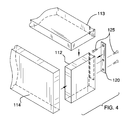
FIG. 4 is an exploded view of the flat screen TV dust protector device of FIG. 1.
FIG. 5 is a perspective in-use view of the flat screen TV dust protector device of the present invention.
FIG. 6 is an alternative embodiment of the flat screen TV dust protector device of the present invention, wherein a first is used above the flat screen television and a second device is used below the flat screen television.
DESCRIPTION OF PREFERRED EMBODIMENTS
Referring now to FIG. 1-6, the present invention features a flat screen TV dust protector device 100 for helping to hide and protect tops of flat screen TV's and curtains to protect the front of flat screen televisions. The flat screen TV dust protector device 100 will help enhance the top appearance of the flat screen TV's, as well as prevent premature replacement. In all embodiments, the flat screen TV dust protector device 100 provides a user with additional storage space for storing and displaying household items and knick-knacks.
The flat screen TV dust protector device 100 comprises an elongated base 110 having a top dust panel 113, a first side panel 111, a second side panel 112, and a front panel 114 (e.g., designated front panel). The top dust panel 113, the first side panel 111, the second side panel 112, and the front panel 114 (e.g., designated front panel) together form an inner cavity. The base 110 is configured to surround the top of flat screen televisions.
The base 110 may be constructed in a variety of sizes. In some embodiments, the base 110 is between about 2 to 3 feet in width as measured from the first end of the top dust panel 113 to the second end of the top dust panel 113. In some embodiments, the base 110 is between about 5-7 feet in width. In some embodiments, the base 110 is between 7-9 feet in width. In some embodiments, the base 110 is 9-11 feet in width. In some embodiments, the base 110 is more than 11 feet in width.
The base 110 can be attached to a wall IDS around the top of a flat screen television via an attachment means. In some embodiments, one or more mounting brackets 120 are disposed on the base 110, for example on top dust panel 113 and\or the first side panel 111 and\or on the second side panel 112. As shown in FIG. 1, two mounting brackets 120 are disposed on the top dust panel 113 of the base 110.
As shown in FIG. 2 and FIG. 3, a support bar 150 may be disposed on the top dust panel 113. The support bar 150 may extend downwardly (e.g., generally perpendicularly to the top dust panel 113 and parallel to the front panel 114). The support bar 150 may provide support for the base 110 while attached to the wall IDS. In some embodiments, the support bar 150 provides an additional means of securing the base 110 to the wall IDS. For example, apertures may be disposed in the support bar 150, which are adapted to receive screws and\or bolts and\or nails. The screws and\or bolts and\or nails can be used to attach the base 110 to the wall IDS.
As shown in FIG. 3, in some embodiments the base 110 (e.g., the front panel 114) comprises a decoration or design 130. The base 110 may be constructed in a variety of shapes and be designed in a number of ways.
FIG. 4 shows an exploded view of the base 110, wherein the second end of the top dust panel 113 is attached to the second side panel 112, and the second end of the front panel 114 is also attached to the second side panel 112. The mounting bracket 120 can be attached to the second side panel 112 via mounting hardware 125. The mounting bracket 120 can also be attached to the top dust panel 113. Mounting hardware may also be used to attach the mounting bracket to the wall 108.
As shown in FIG. 5, the base 110 can be attached to a wall 108 around a curtain and flat screen television. As shown in FIG. 5, the base 110 can be attached to a wall around a flat screen television, wherein curtains 106 are also used. The flat screen television can hang downwardly undisturbed. The top dust panel 113 can also function to display household items and knick-knacks. In some embodiments, two bases 110 a and 110 b are used in the device. For example, a first base 110 a is placed above the flat screen television 600 and a second base 110 b is placed below the flat screen television 600. The curtains 106 can hang from base 110 a, and the bottom of the curtains are inside the base 110 b, so that the television can be completely covered by the closed curtains. This arrangement can provide a balanced appearance if desired.
The present invention also features a method of helping to protect a wall mounted flat screen television from dust. In some embodiments, the method comprises obtaining a flat screen television dust protector device of the present invention and attaching the base to a wall above a flat screen television such that a top area of the flat screen television is positioned inside the inner cavity of the base.
As used herein, the term “about” refers to plus or minus 10% of the referenced number. For example, an embodiment wherein the base 110 is about 5 feet in width includes a base that is 4.5 and 5.5 feet in width.
The following disclosures of the following U.S. Pat. No. 2,824,606; U.S. Pat. No. 4,782,554; U.S. Pat. No. 4,999,874; U.S. Pat. No. 5,259,520; U.S. Pat. No. 20050161169; U.S. Pat. No. 4,120,474; U.S. Pat. No. 4,183,487; U.S. Pat. No. 5,232,039; U.S. Pat. No. 5,505,418; U.S. Pat. No. 5,529,273; U.S. Pat. No. 5,775,656; U.S. Pat. No. 6,532,625; U.S. Pat. No. 7,134,470.
Various modifications of the invention, in addition to those described herein, will be apparent to those skilled in the art from the foregoing description. Such modifications are also intended to fall within the scope of the appended claims. Each reference cited in the present application is incorporated herein by reference in it's entirety.
Although there has been shown and described the preferred embodiment of the present invention, it will be readily apparent to those skilled in the art that modifications may be made thereto which do not exceed the scope of the appended claims. Therefore, the scope of the invention is only limited by the following claims.