US8550688B2 - Backlight assembly with optical member coupling means and display appartus having the same - Google Patents
Backlight assembly with optical member coupling means and display appartus having the same Download PDFInfo
- Publication number
- US8550688B2 US8550688B2 US13/016,289 US201113016289A US8550688B2 US 8550688 B2 US8550688 B2 US 8550688B2 US 201113016289 A US201113016289 A US 201113016289A US 8550688 B2 US8550688 B2 US 8550688B2
- Authority
- US
- United States
- Prior art keywords
- diffusion plate
- supporting part
- backlight assembly
- barrier wall
- receiving
- Prior art date
- Legal status (The legal status is an assumption and is not a legal conclusion. Google has not performed a legal analysis and makes no representation as to the accuracy of the status listed.)
- Expired - Fee Related, expires
Links
Images


Classifications
-
- G—PHYSICS
- G02—OPTICS
- G02F—OPTICAL DEVICES OR ARRANGEMENTS FOR THE CONTROL OF LIGHT BY MODIFICATION OF THE OPTICAL PROPERTIES OF THE MEDIA OF THE ELEMENTS INVOLVED THEREIN; NON-LINEAR OPTICS; FREQUENCY-CHANGING OF LIGHT; OPTICAL LOGIC ELEMENTS; OPTICAL ANALOGUE/DIGITAL CONVERTERS
- G02F1/00—Devices or arrangements for the control of the intensity, colour, phase, polarisation or direction of light arriving from an independent light source, e.g. switching, gating or modulating; Non-linear optics
- G02F1/01—Devices or arrangements for the control of the intensity, colour, phase, polarisation or direction of light arriving from an independent light source, e.g. switching, gating or modulating; Non-linear optics for the control of the intensity, phase, polarisation or colour
- G02F1/13—Devices or arrangements for the control of the intensity, colour, phase, polarisation or direction of light arriving from an independent light source, e.g. switching, gating or modulating; Non-linear optics for the control of the intensity, phase, polarisation or colour based on liquid crystals, e.g. single liquid crystal display cells
- G02F1/133—Constructional arrangements; Operation of liquid crystal cells; Circuit arrangements
- G02F1/1333—Constructional arrangements; Manufacturing methods
- G02F1/1335—Structural association of cells with optical devices, e.g. polarisers or reflectors
- G02F1/1336—Illuminating devices
- G02F1/133602—Direct backlight
- G02F1/133604—Direct backlight with lamps
-
- G—PHYSICS
- G02—OPTICS
- G02F—OPTICAL DEVICES OR ARRANGEMENTS FOR THE CONTROL OF LIGHT BY MODIFICATION OF THE OPTICAL PROPERTIES OF THE MEDIA OF THE ELEMENTS INVOLVED THEREIN; NON-LINEAR OPTICS; FREQUENCY-CHANGING OF LIGHT; OPTICAL LOGIC ELEMENTS; OPTICAL ANALOGUE/DIGITAL CONVERTERS
- G02F1/00—Devices or arrangements for the control of the intensity, colour, phase, polarisation or direction of light arriving from an independent light source, e.g. switching, gating or modulating; Non-linear optics
- G02F1/01—Devices or arrangements for the control of the intensity, colour, phase, polarisation or direction of light arriving from an independent light source, e.g. switching, gating or modulating; Non-linear optics for the control of the intensity, phase, polarisation or colour
- G02F1/13—Devices or arrangements for the control of the intensity, colour, phase, polarisation or direction of light arriving from an independent light source, e.g. switching, gating or modulating; Non-linear optics for the control of the intensity, phase, polarisation or colour based on liquid crystals, e.g. single liquid crystal display cells
- G02F1/133—Constructional arrangements; Operation of liquid crystal cells; Circuit arrangements
- G02F1/1333—Constructional arrangements; Manufacturing methods
- G02F1/1335—Structural association of cells with optical devices, e.g. polarisers or reflectors
- G02F1/1336—Illuminating devices
- G02F1/133602—Direct backlight
- G02F1/133608—Direct backlight including particular frames or supporting means
Definitions
- the present invention relates to a backlight assembly and a display apparatus, more particularly, to a backlight assembly capable of preventing movement of a diffusion plate thereof and a display apparatus having the backlight assembly.
- a liquid crystal display includes a liquid crystal display panel displaying an image and a backlight assembly providing light to the liquid crystal display panel.
- the backlight assembly may be classified as an edge-illumination type backlight assembly and a direct-illumination type backlight assembly based on the position of a lamp that generates the light.
- the edge-illumination type backlight assembly includes a lamp disposed adjacent to a side surface of a light guide plate
- the direct-illumination type backlight assembly includes a plurality of lamps disposed under a diffusion plate.
- the lamps are received in a receiving container and disposed under the liquid crystal display panel.
- the diffusion plate is disposed on the lamps to improve brightness of the light.
- the lamps can be damaged due to the movement of the diffusion plate when external impacts are applied to the diffusion plate.
- the light may leak through a space generated by the movement of the diffusion plate.
- Exemplary embodiments of the present invention provide a backlight assembly capable of preventing movement of a diffusion plate thereof to reduce and/or prevent light leakage and facilitate assembly.
- Exemplary embodiments of the present invention also provide a display apparatus having the backlight assembly.
- a backlight assembly includes a light generating unit that generates a light, a receiving member, an optical member, and a frame member.
- the receiving member includes a receiving part receiving the light generating unit, a supporting part extending from the receiving part, and a protrusion portion protruded from the supporting part.
- the optical member is located at a predetermined position on the supporting part and includes a portion coupled to the protrusion portion.
- the optical member diffuses the light provided from the light generating unit.
- the frame member includes a fixing part coupled with the supporting part and protruded from a surface of the frame member facing the supporting part. The fixing part prevents the optical member from moving in a direction substantially parallel to an upper surface of the supporting part.
- a display apparatus includes a backlight assembly that generates a light and a display panel that receives the light to display an image.
- the backlight assembly includes a light generating unit that generates a light, a receiving member, an optical member, and a frame member.
- the receiving member includes a receiving part receiving the light generating unit, a supporting part extending from the receiving part, and a protrusion portion protruded from the supporting part.
- the optical member is guided to a predetermined position on the supporting part by the protrusion portion, and diffuses the light provided from the light generating unit.
- the frame member includes a fixing part coupled with the supporting part and protruded from a surface facing the supporting part to prevent the optical member from moving in a direction substantially parallel to an upper surface of the supporting part.
- the frame member since the frame member includes the fixing part facing a side surface of the diffusion plate, the diffusion plate may be prevented from moving due to external impacts.
- the construction of the backlight assembly and the display apparatus may prevent the occurrence of assembling defects and light leakage due to movement of the optical member.
- FIG. 1 is an exploded perspective view showing a backlight assembly according to an exemplary embodiment of the present invention
- FIG. 2 is a cross-sectional view taken along a line I-I′ of FIG. 1 ;
- FIG. 3 is an exploded perspective view showing portions of a receiving container, a diffusion plate, and an optical sheet of FIG. 1 ;
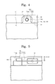
- FIG. 4 is a plan view showing portions of the receiving container, the diffusion plate, and the optical sheet of FIG. 3 ;
- FIG. 5 is a rear plan view showing a portion of a frame member of FIG. 1 ;
- FIG. 6 is a perspective view showing a rear side of the frame member of FIG. 5 ;
- FIG. 7 is a plan view showing the frame member combined with the portions of the receiving member, the diffusion plate, and the optical sheet of FIG. 4 ;
- FIG. 8 is a cross-sectional view taken along a line II-II′ of FIG. 7 ;
- FIG. 9 is a cross-sectional view showing a backlight assembly according to an exemplary embodiment of the present invention.
- FIG. 10 is an exploded perspective view showing a liquid crystal display according to an exemplary embodiment of the present invention.
- FIG. 11 is a cross-sectional view taken along a line III-III′ of FIG. 10 .
- FIG. 1 is an exploded perspective view showing a backlight assembly according to an exemplary embodiment of the present invention
- FIG. 2 is a cross-sectional view taken along a line I-I′ of FIG. 1 .
- a backlight assembly 100 includes a light generating unit 110 , a receiving member 120 , an optical member 130 , and a frame member 140 .
- the light generating unit 110 includes a plurality of lamps 111 each generating light and a plurality of lamp holders 112 .
- the lamps 111 generate the light in response to a driving voltage and each lamp may be a cold cathode fluorescent lamp having a cylindrical bar shape.
- the lamps 111 may be arranged at regular intervals in order to improve brightness uniformity of the backlight assembly 100 .
- the lamps 111 each may be an external electrode fluorescent lamp provided with external electrodes at both ends thereof.
- the lamp holders 112 are arranged at both ends of the lamp 111 to hold the both ends of the lamps 111 to prevent the movement of the lamps 111 .
- each of the lamp holders 112 may be coupled with two lamps 111 adjacent to each other.
- the receiving member 120 includes a receiving part 121 receiving the light generating unit 110 therein and a supporting part 122 supporting the optical member 130 .
- the receiving part 121 includes a bottom surface 121 a and a sidewall 121 b extended from the bottom surface 121 a , and the bottom surface 121 a has a rectangular-like shape.
- the sidewall 121 b extends from edges of the bottom surface 121 a to provide a receiving space in which the light generating unit 100 is received.
- the receiving member 120 may be formed of a metal material, for example, an aluminum-based metal having requisite strength and deforming resistance, in order to effectively discharge heat generated in the light generating unit 100 .
- the aluminum-based metal may have a relatively high strength and low deforming resistance.
- the backlight assembly 100 may further include a side mold (not shown) disposed at the sidewall 121 b of the receiving member 120 adjacent to the both ends of the lamps 111 to hold the both ends of the lamps 111 .
- the side mold covers the lamp holders 112 , thereby preventing non-uniformity of brightness of the backlight assembly 100 .
- the backlight assembly 100 further includes a reflection sheet 135 disposed under the light generating unit 110 .
- the reflection sheet 135 reflects the light leaked from the light generating unit 110 to the optical member 130 to improve a light using efficiency.
- the reflection sheet 135 may include polyethylene terephthalate (PET) or polycarbonate (PC).
- the supporting part 122 of the receiving member 120 includes an upper surface on which the optical member 130 is mounted and a protrusion portion 123 protruded from the upper surface of the supporting part 122 to guide the optical member 130 to a predetermined position on the supporting part 122 .
- the optical member 130 is guided by the protrusion portion 123 to the predetermined position on the supporting part 122 . Once in position, the optical member 130 may receive the light from the light generating unit 110 and diffuse the light.
- the optical member 130 includes a diffusion plate 131 and optical sheets 132 , 133 , and 134 disposed on the diffusion plate 131 .
- the protrusion portion 123 has a two-tiered protruding structure.
- the protrusion portion 123 includes a guide portion 123 a protruded from the supporting part 122 to guide the diffusion plate 131 and a coupling protrusion 123 b coupled with the optical sheets 132 , 133 , and 134 .
- the diffusion plate 131 has a plate-like shape and is guided by the guide portion 123 a to the predetermined position of the supporting part 122 . Accordingly, the diffusion plate 131 is disposed on the light generating unit 110 and diffuses the light from the light generating unit 110 to improve the brightness uniformity. In addition, the diffusion plate 131 may support the optical sheets 132 , 133 , and 134 such that the optical sheets 132 , 133 , and 134 do not sag.
- the optical sheets 132 , 133 , and 134 are disposed on the diffusion plate 131 and improve the brightness characteristics of the light exiting from the diffusion plate 131 .
- the optical sheets 132 , 133 , and 134 may include a diffusion sheet 132 to diffuse the light and two light collection sheets 133 and 134 to collect the light.
- the diffusion sheet 132 is disposed on the diffusion plate 131 and diffuses the light from the diffusion plate 131 .
- the diffusion sheet 132 may be formed of a transparent material such as polyethylene terephthalate.
- the light collection sheets 133 and 134 are disposed on the diffusion sheet 132 and collect the light diffused by the diffusion sheet 132 to improve a front brightness.
- Each of the light collection sheets 133 and 134 may include a fine prism pattern (not shown). Specifically, the prism pattern of one of the light collection sheets 133 and 134 extends in a first direction D 1 and the prism pattern of the remaining one of the light collection sheets 133 and 134 extends in a second direction D 2 substantially perpendicular to the first direction D 1 .
- Each of the diffusion sheet 132 and the light collection sheets 133 and 134 may include a light transmitting portion A 1 and a sheet fixing portion A 2 .
- the light transmitting portion A 1 is positioned over the lamps 110 and the light emitted from the lamps 110 is transmitted through the light transmitting portion A 1 .
- the sheet fixing portion(s) A 2 is formed by extending an end of the light transmitting portion A 1 so that the sheet fixing portion A 2 protrudes from the light transmitting portion A 1 .
- the sheet fixing portion A 2 is provided in two locations on each of two ends of the light transmitting portion A 1 , and thus four protrusion portions 123 (two on each side) may be provided on the supporting part 122 of the receiving member 120 .
- FIG. 3 is an exploded perspective view showing portions of a receiving container, a diffusion plate, and an optical sheet of FIG. 1 and FIG. 4 is a plan view showing portions of the receiving container, the diffusion plate, and the optical sheet of FIG. 3 .
- the sheet fixing portion A 2 is provided with a fixing hole 130 a formed therethrough in order to fix the optical sheets 132 , 133 , and 134 to the coupling protrusion 123 b of the receiving member 120 .
- the coupling protrusion 123 b formed on the protrusion portion 123 of the receiving member 120 is inserted into the fixing hole 130 a to fix the optical sheets 132 , 133 , and 134 to the receiving member 120 .
- the coupling protrusion 123 b of the protrusion portion 123 has a circular column shape and is integrally formed with the guide portion 123 a .
- the coupling protrusion 123 b includes an upper portion having a round shape.
- the coupling protrusion 123 b may have a convex semi-circular shape of which an outer diameter decreases closer to the upper end of the coupling protrusion 123 b.
- the coupling hole 130 a may have a diameter equal to or smaller than a diameter of the coupling protrusion 123 b to prevent the sheet fixing portion A 2 from being separated from the coupling protrusion 123 b .
- the optical sheets 132 , 133 , and 134 have elasticity, so that the coupling protrusion 123 b may be inserted into the fixing hole 130 a having the diameter equal to or smaller than a diameter of the coupling protrusion 123 b formed through the sheet fixing portion A 2 . Accordingly, the sheet fixing portion A 2 may prevent the deviation of the light transmitting portion A 1 from its original position.
- the frame member 140 of the backlight assembly 100 is coupled with the supporting part 122 of the receiving member 120 in a position facing the supporting part 122 of the receiving member 120 .
- FIG. 5 is a rear plan view showing a portion of a frame member of FIG. 1
- FIG. 6 is a perspective view showing a rear side of the frame member of FIG. 5 .
- the frame member 140 includes a fixing part 141 protruded from a surface opposite to the supporting part 122 and facing a surface of the diffusion plate 131 .
- the fixing part 141 includes a first barrier wall 141 a extended in a third direction D 3 , a second barrier wall 141 b extended in a fourth direction D 4 substantially perpendicular to the third direction D 3 , and a third barrier wall 141 c extended in the fourth direction D 4 .
- the first barrier wall 141 a faces the surface of the diffusion plate 131 and prevents the diffusion plate 131 from moving toward a direction (e.g., the second direction D 2 ) substantially parallel to a length of the upper surface of the supporting part 122 .
- the second and third barrier walls 141 b and 141 c are respectively connected with both ends of the first barrier wall 141 a to support the first barrier wall 141 a.
- the frame member 140 includes a receiving recess 142 formed on the surface opposite to the supporting part 122 to receive the protrusion portion 123 .
- the fixing part 141 is spaced apart from the receiving recess 142 by a predetermined distance.
- FIG. 7 is a plan view showing the frame member combined with the portions of the receiving member, the diffusion plate, and the optical sheet of FIG. 4
- FIG. 8 is a cross-sectional view taken along a line II-II′ of FIG. 7 .
- the fixing part 141 may be positioned at a position close to the protrusion portion 123 .
- the first barrier wall 141 a and the side surface of the guide portion 123 a neighboring the diffusion plate 131 are positioned on the same straight line as each other.
- the first barrier wall 141 a protrudes from the opposite surface of the frame member 140 in a direction perpendicular to the upper surface of the diffusion plate to face a side surface of the diffusion plate 131 .
- the first barrier wall 141 a may prevent the diffusion plate 131 from moving in the second direction D 2 , thereby preventing the upward movement of an end portion of the diffusion plate 131 above the guide portion 123 a even if external impacts are applied to the diffusion plate 131 .
- the guide portion 123 a has a height substantially equal to a thickness of the diffusion plate 131 . If the height of the guide portion 123 a were greater than the thickness of the diffusion plate 131 , a distance space would be generated between the diffusion plate 131 and the optical sheets 132 , 133 , and 134 due to the sheet fixing portion A 2 , thereby causing deterioration in brightness. On the contrary, if the height of the guide portion 123 a were smaller than the thickness of the diffusion plate 131 , the adhesive force between the sheet fixing portion A 2 and the coupling protrusion 123 b would be deteriorated. Accordingly, according to an embodiment, the height of the guide portion 123 a is substantially equal to a thickness of the diffusion plate 131 .
- the end portion of the diffusion plate 131 may be prevented from upwardly moving above the guide portion 123 a due to external impacts.
- the diffusion plate 131 may still be prevented from moving due to external impacts.
- the fixing part 141 may further include the second and third barrier walls 141 b and 141 c to disperse the force applied to the first barrier wall 141 a.
- FIG. 9 is a cross-sectional view showing a backlight assembly according to an exemplary embodiment of the present invention.
- the same reference numerals denote the same or similar elements in FIG. 2 , and thus detailed descriptions of these elements will be omitted.
- a backlight assembly 101 includes a light generating unit 160 , a receiving member 120 , an optical member 130 , and a frame member 140 .
- the light generating unit 160 includes a circuit board 161 and a plurality of light sources 162 mounted on the circuit board 161 .
- the circuit board 161 is received in a receiving part 121 of the receiving member 120 to face the optical member 130 .
- the light sources 162 may be arranged on the circuit board 161 in a matrix configuration.
- each of the light sources 162 may include a white light emitting diode that emits white light.
- the light sources 162 may include a red light emitting diode emitting red light, a green light emitting diode emitting green light, and a blue light emitting diode emitting blue light, and the red, green, and blue light emitting diodes may be turned on in sequence.
- the light generating unit 160 may further include a reflection sheet 165 disposed on an upper surface of the circuit board 161 (i.e., the surface on which the light sources 162 are mounted).
- the reflection sheet 165 may include openings formed therethrough corresponding to the light sources 162 .
- the reflection sheet 165 reflects the light emitted from the light sources 162 to the optical member 130 to improve light efficiency.
- the first barrier wall 141 a is positioned to face a side surface of the diffusion plate 131 , thereby preventing the diffusion plate 131 from moving due to external impacts.
- FIG. 10 is an exploded perspective view showing a liquid crystal display according to an exemplary embodiment of the present invention
- FIG. 11 is a cross-sectional view taken along a line III-III′ of FIG. 10 .
- a liquid crystal display 300 includes a backlight assembly 100 that generates the light and a liquid crystal display panel 210 that receives the light to display an image.
- the backlight assembly 100 may have the same configurations as those of the backlight assemblies shown in FIGS. 1 to 8 , and thus repetitive descriptions thereof will be omitted.
- the liquid crystal display panel 210 includes an array substrate 211 , an opposite substrate 213 coupled with the array substrate 211 to face the array substrate 211 , and a liquid crystal layer (not shown) disposed between the array substrate 211 and the opposite substrate 213 .
- the array substrate 211 may be a thin film transistor (TFT) substrate on which thin film transistors are arranged in a matrix configuration.
- TFTs includes a gate electrode connected to a gate line, a source electrode connected to a data line, and a drain electrode connected to a pixel electrode including a transparent conductive material.
- the opposite substrate 213 may include RGB color filters, a black matrix, and a common electrode of a transparent conductive material.
- the liquid crystal display 300 includes a printed circuit board 215 to apply a gate driving signal and a data driving signal to the liquid crystal display panel 210 and a driving circuit film 217 to connect the printed circuit board 215 with the liquid crystal display panel 210 .
- the driving circuit film 217 may be a tape carrier package (TCP) on which a driving chip 219 is mounted or a chip on film (COF).
- TCP tape carrier package
- COF chip on film
- the driving chip 219 may include a data driver that applies a data signal to the liquid crystal display panel 210 in response to the data driving signal.
- a gate driver (not shown) that applies a gate signal to the liquid crystal display panel 210 in response to the gate driving signal may be built in the liquid crystal display panel 210 through a thin film process.
- the backlight assembly 100 includes the frame member 140 disposed between the optical member 130 and the liquid crystal display panel 210 .
- the frame member 140 is coupled with the receiving member 120 to fix the optical member 130 to the receiving member 120 , thereby preventing the movement of the diffusion plate 131 by using the fixing part 141 .
- the frame member 140 supports the liquid crystal display panel 210 .
- the frame member 140 further includes a panel guide portion 143 , on which the liquid crystal display panel 210 is mounted.
- the guide portion 143 includes a recessed surface formed around the perimeter of the frame member 140 on which the liquid crystal display panel 210 rests.
- the liquid crystal display 300 is coupled with the frame member 140 and further includes a top chassis 230 to fix the liquid crystal display panel 210 on the frame member 140 .
- the top chassis 230 covers an end portion of the liquid crystal display panel 210 and fixes the liquid crystal display panel 210 to the panel guide portion 143 of the frame member 140 .
- the top chassis 230 may prevent the liquid crystal display panel 210 from being damaged due to external impacts and the liquid crystal display panel 210 from being separated from the panel guide portion 143 of the frame member 140 .
Abstract
Description
Claims (18)
Applications Claiming Priority (2)
| Application Number | Priority Date | Filing Date | Title |
|---|---|---|---|
| KR1020100016726A KR20110097086A (en) | 2010-02-24 | 2010-02-24 | Backlight assembly and display apparatus having the same |
| KR10-2010-0016726 | 2010-02-24 |
Publications (2)
| Publication Number | Publication Date |
|---|---|
| US20110205728A1 US20110205728A1 (en) | 2011-08-25 |
| US8550688B2 true US8550688B2 (en) | 2013-10-08 |
Family
ID=44476328
Family Applications (1)
| Application Number | Title | Priority Date | Filing Date |
|---|---|---|---|
| US13/016,289 Expired - Fee Related US8550688B2 (en) | 2010-02-24 | 2011-01-28 | Backlight assembly with optical member coupling means and display appartus having the same |
Country Status (2)
| Country | Link |
|---|---|
| US (1) | US8550688B2 (en) |
| KR (1) | KR20110097086A (en) |
Cited By (6)
| Publication number | Priority date | Publication date | Assignee | Title |
|---|---|---|---|---|
| US20120170250A1 (en) * | 2010-12-30 | 2012-07-05 | Sheng-Bei Huang | Backlight module and display device utilizing the same |
| CN103955094A (en) * | 2014-05-15 | 2014-07-30 | 瑞仪光电股份有限公司 | Frame mechanism for optical equipment |
| US20150355404A1 (en) * | 2014-06-10 | 2015-12-10 | Samsung Display Co., Ltd. | Display device |
| WO2016061831A1 (en) * | 2014-10-22 | 2016-04-28 | 深圳市华星光电技术有限公司 | Liquid crystal display device and backlight module thereof |
| US20180292597A1 (en) * | 2016-08-23 | 2018-10-11 | Boe Technology Group Co., Ltd. | Film, backlight module and display device |
| US11105492B2 (en) * | 2019-10-31 | 2021-08-31 | K-Tronics (Suzhou) Technology Co., Ltd. | Backlight module and display device |
Families Citing this family (6)
| Publication number | Priority date | Publication date | Assignee | Title |
|---|---|---|---|---|
| TWI446072B (en) * | 2011-10-05 | 2014-07-21 | Au Optronics Corp | Backlight module |
| CN102767758A (en) * | 2012-07-03 | 2012-11-07 | 深圳市华星光电技术有限公司 | Backlight module and LCD including same |
| KR102024862B1 (en) * | 2016-10-19 | 2019-09-25 | 삼성디스플레이 주식회사 | Display apparatus |
| KR102642344B1 (en) * | 2018-09-28 | 2024-02-29 | 삼성디스플레이 주식회사 | Display device |
| CN110133911A (en) * | 2019-05-15 | 2019-08-16 | 京东方科技集团股份有限公司 | Backlight module and airborne display device |
| WO2022097720A1 (en) * | 2020-11-05 | 2022-05-12 | 三菱電機株式会社 | Display device |
Citations (18)
| Publication number | Priority date | Publication date | Assignee | Title |
|---|---|---|---|---|
| US6175396B1 (en) * | 1998-01-24 | 2001-01-16 | Samsung Electronics Co., Ltd. | Liquid crystal display module |
| US20020041492A1 (en) * | 2000-10-05 | 2002-04-11 | Advanced Display Inc. | Planar light source device and liquid crystal display device |
| US20040109308A1 (en) * | 2002-12-07 | 2004-06-10 | Yi-Chun Ho | Device for fixing layers of optic film of backlight module |
| US6835961B2 (en) * | 2000-12-25 | 2004-12-28 | Hitachi, Ltd. | Liquid crystal display device |
| US6867824B2 (en) * | 2001-12-28 | 2005-03-15 | Fujitsu Display Technologies Corporation | Display device |
| US6950154B2 (en) * | 2002-05-28 | 2005-09-27 | Samsung Electronics Co., Ltd. | Backlight assembly having fixing recess in light guide and liquid crystal display apparatus having the same |
| US7125157B2 (en) * | 2004-05-13 | 2006-10-24 | Au Optronics Corp. | Backlight unit and liquid crystal display utilizing the same |
| US7184110B2 (en) * | 2000-08-21 | 2007-02-27 | Lg.Philips Lcd Co., Ltd. | Liquid crystal display with main frame comprising a shaft member |
| US7224416B2 (en) * | 2002-07-26 | 2007-05-29 | Samsung Electronics Co., Ltd. | Backlight assembly using the same and liquid crystal display device |
| US7324174B2 (en) * | 2004-08-04 | 2008-01-29 | Sony Corporation | Backlight device and liquid crystal display apparatus |
| US7380972B2 (en) * | 2002-08-28 | 2008-06-03 | Sharp Kabushiki Kaisha | Lighting system and liquid crystal backlight device |
| US7443460B2 (en) * | 2005-11-16 | 2008-10-28 | Lg Display Co., Ltd. | Backlight assembly for liquid crystal display and liquid crystal display module using the same |
| US7481569B2 (en) * | 2005-12-07 | 2009-01-27 | Hon Hai Precision Industry Co., Ltd. | Direct type backlight module |
| US7543975B2 (en) * | 2007-01-16 | 2009-06-09 | Au Optronics Corporation | Optical film and backlight module, display device and electro-optical device including thereof |
| US20100027241A1 (en) * | 2008-07-31 | 2010-02-04 | Epson Imaging Devices Corporation | Backlight unit, electro-optical device, and electronic apparatus |
| US7780333B2 (en) * | 2007-12-21 | 2010-08-24 | Hong Fu Jin Precision Industry (Shenzhen) Co., Ltd. | Optical plate with optical sheet fixing means and backlight module using the same |
| US7973872B2 (en) * | 2008-02-15 | 2011-07-05 | Lg Display Co., Ltd. | Backlight unit and liquid crystal display using the same |
| US8085362B2 (en) * | 2008-12-24 | 2011-12-27 | Funai Electric Co., Ltd. | Liquid crystal module |
-
2010
- 2010-02-24 KR KR1020100016726A patent/KR20110097086A/en not_active Application Discontinuation
-
2011
- 2011-01-28 US US13/016,289 patent/US8550688B2/en not_active Expired - Fee Related
Patent Citations (18)
| Publication number | Priority date | Publication date | Assignee | Title |
|---|---|---|---|---|
| US6175396B1 (en) * | 1998-01-24 | 2001-01-16 | Samsung Electronics Co., Ltd. | Liquid crystal display module |
| US7184110B2 (en) * | 2000-08-21 | 2007-02-27 | Lg.Philips Lcd Co., Ltd. | Liquid crystal display with main frame comprising a shaft member |
| US20020041492A1 (en) * | 2000-10-05 | 2002-04-11 | Advanced Display Inc. | Planar light source device and liquid crystal display device |
| US6835961B2 (en) * | 2000-12-25 | 2004-12-28 | Hitachi, Ltd. | Liquid crystal display device |
| US6867824B2 (en) * | 2001-12-28 | 2005-03-15 | Fujitsu Display Technologies Corporation | Display device |
| US6950154B2 (en) * | 2002-05-28 | 2005-09-27 | Samsung Electronics Co., Ltd. | Backlight assembly having fixing recess in light guide and liquid crystal display apparatus having the same |
| US7224416B2 (en) * | 2002-07-26 | 2007-05-29 | Samsung Electronics Co., Ltd. | Backlight assembly using the same and liquid crystal display device |
| US7380972B2 (en) * | 2002-08-28 | 2008-06-03 | Sharp Kabushiki Kaisha | Lighting system and liquid crystal backlight device |
| US20040109308A1 (en) * | 2002-12-07 | 2004-06-10 | Yi-Chun Ho | Device for fixing layers of optic film of backlight module |
| US7125157B2 (en) * | 2004-05-13 | 2006-10-24 | Au Optronics Corp. | Backlight unit and liquid crystal display utilizing the same |
| US7324174B2 (en) * | 2004-08-04 | 2008-01-29 | Sony Corporation | Backlight device and liquid crystal display apparatus |
| US7443460B2 (en) * | 2005-11-16 | 2008-10-28 | Lg Display Co., Ltd. | Backlight assembly for liquid crystal display and liquid crystal display module using the same |
| US7481569B2 (en) * | 2005-12-07 | 2009-01-27 | Hon Hai Precision Industry Co., Ltd. | Direct type backlight module |
| US7543975B2 (en) * | 2007-01-16 | 2009-06-09 | Au Optronics Corporation | Optical film and backlight module, display device and electro-optical device including thereof |
| US7780333B2 (en) * | 2007-12-21 | 2010-08-24 | Hong Fu Jin Precision Industry (Shenzhen) Co., Ltd. | Optical plate with optical sheet fixing means and backlight module using the same |
| US7973872B2 (en) * | 2008-02-15 | 2011-07-05 | Lg Display Co., Ltd. | Backlight unit and liquid crystal display using the same |
| US20100027241A1 (en) * | 2008-07-31 | 2010-02-04 | Epson Imaging Devices Corporation | Backlight unit, electro-optical device, and electronic apparatus |
| US8085362B2 (en) * | 2008-12-24 | 2011-12-27 | Funai Electric Co., Ltd. | Liquid crystal module |
Cited By (9)
| Publication number | Priority date | Publication date | Assignee | Title |
|---|---|---|---|---|
| US20120170250A1 (en) * | 2010-12-30 | 2012-07-05 | Sheng-Bei Huang | Backlight module and display device utilizing the same |
| US8662693B2 (en) * | 2010-12-30 | 2014-03-04 | Au Optronics Corp. | Backlight module and display device utilizing the same |
| CN103955094A (en) * | 2014-05-15 | 2014-07-30 | 瑞仪光电股份有限公司 | Frame mechanism for optical equipment |
| US20150355404A1 (en) * | 2014-06-10 | 2015-12-10 | Samsung Display Co., Ltd. | Display device |
| US9395484B2 (en) * | 2014-06-10 | 2016-07-19 | Samsung Display Co., Ltd. | Display device |
| WO2016061831A1 (en) * | 2014-10-22 | 2016-04-28 | 深圳市华星光电技术有限公司 | Liquid crystal display device and backlight module thereof |
| US20180292597A1 (en) * | 2016-08-23 | 2018-10-11 | Boe Technology Group Co., Ltd. | Film, backlight module and display device |
| US10324248B2 (en) * | 2016-08-23 | 2019-06-18 | Boe Technology Group Co., Ltd. | Film, backlight module and display device |
| US11105492B2 (en) * | 2019-10-31 | 2021-08-31 | K-Tronics (Suzhou) Technology Co., Ltd. | Backlight module and display device |
Also Published As
| Publication number | Publication date |
|---|---|
| US20110205728A1 (en) | 2011-08-25 |
| KR20110097086A (en) | 2011-08-31 |
Similar Documents
| Publication | Publication Date | Title |
|---|---|---|
| US8550688B2 (en) | Backlight assembly with optical member coupling means and display appartus having the same | |
| US7270467B2 (en) | Backlight assembly and flat panel display apparatus having the same | |
| US7220045B2 (en) | Backlight assembly and liquid crystal display device having the same | |
| US7583330B2 (en) | Liquid crystal display apparatus | |
| US7697086B2 (en) | Container, display apparatus including the same, and method of manufacturing display apparatus | |
| US7948573B2 (en) | Back-light assembly and liquid crystal display including the same | |
| US7044629B2 (en) | Lamp assembly and liquid crystal display device having the same | |
| US8436963B2 (en) | Backlight assembly and liquid crystal display having the same | |
| US20050168954A1 (en) | Chassis and display device having the same | |
| US20080297698A1 (en) | Light illuminating unit and liquid crystal display device having the same | |
| US8553169B2 (en) | Display device and method of assembling the same | |
| US8514347B2 (en) | Backlight unit and liquid crystal display including the same | |
| US8441597B2 (en) | Liquid crystal display device for preventing light leakage | |
| US20090073338A1 (en) | Backlight assembly and method of assembling the same | |
| US20150219955A1 (en) | Display device | |
| US20080130315A1 (en) | Backlight assembly and display device having the same | |
| KR20090046405A (en) | Backlight unit for liquid crystal display device and liquid crystal display device module | |
| KR101699669B1 (en) | Liquid crystal display device | |
| KR20110030226A (en) | Liquid crystal display device | |
| US10802310B2 (en) | Display device | |
| KR20090053087A (en) | Optical sheet and backlight module using the same | |
| KR102484865B1 (en) | Display device | |
| KR20060111784A (en) | Back light assembly and liquid crystal display apparatus having the same | |
| KR20070056495A (en) | Back light assembly and liquid crystal display apparatus having the same | |
| KR20060110652A (en) | Backlight assembly and display apparatus having the same |
Legal Events
| Date | Code | Title | Description |
|---|---|---|---|
| AS | Assignment |
Owner name: SAMSUNG ELECTRONICS CO., LTD, KOREA, REPUBLIC OF Free format text: ASSIGNMENT OF ASSIGNORS INTEREST;ASSIGNORS:SEO, JEONG-MIN;LEE, YOUNGHO;CHUN, JAEHWAN;AND OTHERS;REEL/FRAME:025713/0666 Effective date: 20100727 |
|
| AS | Assignment |
Owner name: SAMSUNG DISPLAY CO., LTD., KOREA, REPUBLIC OF Free format text: ASSIGNMENT OF ASSIGNORS INTEREST;ASSIGNOR:SAMSUNG ELECTRONICS CO., LTD.;REEL/FRAME:029045/0860 Effective date: 20120904 |
|
| STCF | Information on status: patent grant |
Free format text: PATENTED CASE |
|
| FEPP | Fee payment procedure |
Free format text: PAYOR NUMBER ASSIGNED (ORIGINAL EVENT CODE: ASPN); ENTITY STATUS OF PATENT OWNER: LARGE ENTITY |
|
| FPAY | Fee payment |
Year of fee payment: 4 |
|
| FEPP | Fee payment procedure |
Free format text: MAINTENANCE FEE REMINDER MAILED (ORIGINAL EVENT CODE: REM.); ENTITY STATUS OF PATENT OWNER: LARGE ENTITY |
|
| LAPS | Lapse for failure to pay maintenance fees |
Free format text: PATENT EXPIRED FOR FAILURE TO PAY MAINTENANCE FEES (ORIGINAL EVENT CODE: EXP.); ENTITY STATUS OF PATENT OWNER: LARGE ENTITY |
|
| STCH | Information on status: patent discontinuation |
Free format text: PATENT EXPIRED DUE TO NONPAYMENT OF MAINTENANCE FEES UNDER 37 CFR 1.362 |
|
| FP | Lapsed due to failure to pay maintenance fee |
Effective date: 20211008 |