US8550224B2 - Energy absorption system - Google Patents
Energy absorption system Download PDFInfo
- Publication number
- US8550224B2 US8550224B2 US12/420,186 US42018609A US8550224B2 US 8550224 B2 US8550224 B2 US 8550224B2 US 42018609 A US42018609 A US 42018609A US 8550224 B2 US8550224 B2 US 8550224B2
- Authority
- US
- United States
- Prior art keywords
- energy absorption
- piston element
- sheet
- absorption system
- movable carriage
- Prior art date
- Legal status (The legal status is an assumption and is not a legal conclusion. Google has not performed a legal analysis and makes no representation as to the accuracy of the status listed.)
- Active, expires
Links
- 238000010521 absorption reaction Methods 0.000 title claims abstract description 54
- 239000000463 material Substances 0.000 claims abstract description 45
- 230000008878 coupling Effects 0.000 claims description 13
- 238000010168 coupling process Methods 0.000 claims description 13
- 238000005859 coupling reaction Methods 0.000 claims description 13
- 238000005452 bending Methods 0.000 claims description 11
- 230000000694 effects Effects 0.000 description 10
- 230000035939 shock Effects 0.000 description 10
- 208000035874 Excoriation Diseases 0.000 description 1
- 239000006096 absorbing agent Substances 0.000 description 1
- 238000010276 construction Methods 0.000 description 1
- 238000004519 manufacturing process Methods 0.000 description 1
- 230000010355 oscillation Effects 0.000 description 1
- 238000003466 welding Methods 0.000 description 1
Images


Classifications
-
- F—MECHANICAL ENGINEERING; LIGHTING; HEATING; WEAPONS; BLASTING
- F16—ENGINEERING ELEMENTS AND UNITS; GENERAL MEASURES FOR PRODUCING AND MAINTAINING EFFECTIVE FUNCTIONING OF MACHINES OR INSTALLATIONS; THERMAL INSULATION IN GENERAL
- F16F—SPRINGS; SHOCK-ABSORBERS; MEANS FOR DAMPING VIBRATION
- F16F7/00—Vibration-dampers; Shock-absorbers
- F16F7/12—Vibration-dampers; Shock-absorbers using plastic deformation of members
- F16F7/123—Deformation involving a bending action, e.g. strap moving through multiple rollers, folding of members
-
- B—PERFORMING OPERATIONS; TRANSPORTING
- B60—VEHICLES IN GENERAL
- B60N—SEATS SPECIALLY ADAPTED FOR VEHICLES; VEHICLE PASSENGER ACCOMMODATION NOT OTHERWISE PROVIDED FOR
- B60N2/00—Seats specially adapted for vehicles; Arrangement or mounting of seats in vehicles
- B60N2/24—Seats specially adapted for vehicles; Arrangement or mounting of seats in vehicles for particular purposes or particular vehicles
- B60N2/42—Seats specially adapted for vehicles; Arrangement or mounting of seats in vehicles for particular purposes or particular vehicles the seat constructed to protect the occupant from the effect of abnormal g-forces, e.g. crash or safety seats
- B60N2/4207—Seats specially adapted for vehicles; Arrangement or mounting of seats in vehicles for particular purposes or particular vehicles the seat constructed to protect the occupant from the effect of abnormal g-forces, e.g. crash or safety seats characterised by the direction of the g-forces
- B60N2/4242—Seats specially adapted for vehicles; Arrangement or mounting of seats in vehicles for particular purposes or particular vehicles the seat constructed to protect the occupant from the effect of abnormal g-forces, e.g. crash or safety seats characterised by the direction of the g-forces vertical
-
- B—PERFORMING OPERATIONS; TRANSPORTING
- B60—VEHICLES IN GENERAL
- B60N—SEATS SPECIALLY ADAPTED FOR VEHICLES; VEHICLE PASSENGER ACCOMMODATION NOT OTHERWISE PROVIDED FOR
- B60N2/00—Seats specially adapted for vehicles; Arrangement or mounting of seats in vehicles
- B60N2/24—Seats specially adapted for vehicles; Arrangement or mounting of seats in vehicles for particular purposes or particular vehicles
- B60N2/42—Seats specially adapted for vehicles; Arrangement or mounting of seats in vehicles for particular purposes or particular vehicles the seat constructed to protect the occupant from the effect of abnormal g-forces, e.g. crash or safety seats
- B60N2/427—Seats or parts thereof displaced during a crash
- B60N2/42727—Seats or parts thereof displaced during a crash involving substantially rigid displacement
- B60N2/42736—Seats or parts thereof displaced during a crash involving substantially rigid displacement of the whole seat
-
- B—PERFORMING OPERATIONS; TRANSPORTING
- B60—VEHICLES IN GENERAL
- B60N—SEATS SPECIALLY ADAPTED FOR VEHICLES; VEHICLE PASSENGER ACCOMMODATION NOT OTHERWISE PROVIDED FOR
- B60N2/00—Seats specially adapted for vehicles; Arrangement or mounting of seats in vehicles
- B60N2/24—Seats specially adapted for vehicles; Arrangement or mounting of seats in vehicles for particular purposes or particular vehicles
- B60N2/42—Seats specially adapted for vehicles; Arrangement or mounting of seats in vehicles for particular purposes or particular vehicles the seat constructed to protect the occupant from the effect of abnormal g-forces, e.g. crash or safety seats
- B60N2/427—Seats or parts thereof displaced during a crash
- B60N2/42772—Seats or parts thereof displaced during a crash characterised by the triggering system
- B60N2/42781—Seats or parts thereof displaced during a crash characterised by the triggering system mechanical triggering
Definitions
- the present invention relates to an energy absorption system, which is in particular suited for seats in helicopters, air planes and motor vehicles.
- the energy absorption system consists of a movable carriage, a fixed bearing and a deformable material strip, wherein the deformable material strip is at least areally connected to the fixed bearing.
- the energy absorption system may be adjusted to a weight range being suited for the passenger.
- shock absorbers which store the energy by means of spring effect and transfer the energy over a longer range of time being determined by the oscillation period, so that the shock may be reduced.
- An improved absorption of shocks is achieved when the shock energy is transformed into a non-mechanical energy.
- Such systems are designated as energy absorption systems. The energy absorption is thereby enabled through one or more absorption elements.
- an energy absorption element in which between two profile parts a material strip is located, which is attached in a areally removable manner at one profile part and is permanently attached to the other profile part. If a shock or tension occurs between the two profile parts, the energy from the areal connection between the material strip and the profile part is absorbed, in such a way that the areal attachment is removed.
- the known material strip is for example attached by bonding, welding or by means of rivets. Removing of the material strip requires energy, whereby the shock energy is used up.
- the material strip consists of flexible and tear-resistant material. Since in these energy absorption elements the deformation is not crucial for the energy absorption, various materials may be applied. This characteristic is advantageous for the light weight construction and enables a cost efficient production.
- This known material strip has in the past been used among others in energy absorption systems for helicopter seats.
- the material strip was thereby fixably attached to a movable carriage and attached areally strippable at the seat leg.
- a weight depending limitation of the carriage stroke has not been possible up to now.
- an energy absorption system which comprises a movable carriage, a fixed bearing and a deformable material strip, wherein the deformable material strip is at least areally connected to the fixed bearing and wherein between the movable carriage and the fixed bearing a gap is formed, wherein the energy absorption system further comprises means, which are suited to vary the size of the gap which is formed between the movable carriage and the fixed bearing.
- the deformable material strip is arranged between the movable carriage and the fixed bearing in a substantially U-shaped configuration. Due to this geometric arrangement, the shock energy may, during a relative movement of the carriage with regard to the bearing, be absorbed in a particular efficient manner through the respective removing of the strip from the fixed bearing.
- the carriage will, for example during an ismetle landing, move downwards in the direction of the cabin floor (i.e. a pressure force is present) wherein the U-shaped configuration of the material strip is upside down.
- a tensile force has to be absorbed, wherein then the U-shaped configuration is respectively arranged contrary-wise.
- the material strip regularly consists of a flexible and tear-resistant material.
- the means comprise a first sheet and a second sheet, which may be coupled to the movable carriage.
- the carriage may (1) be coupled neither with the first nor with the second sheet, (2) only be coupled with one of the two sheets or finally (3) be coupled with both sheets. Due to these coupling options, the size of the gap between the movable carriage and the fixed bearing may be provided variable.
- the gap comprises the largest size
- the gap comprises a medium size
- the gap comprises the narrowest size. The narrower the gap is adjusted the more bent is the U-shaped configuration of the material strip if the carriage is—with one or both sheets—moved in the direction of the cabin floor.
- a stronger bending of the material strip provides that the stroke of the carriage, with the same force effect, is smaller as if a less strong bending is provided.
- the hub of the carriage may be chosen in such a way, that also if persons with different weight sit onto the seat, a certain threshold respectively maximum value is not exceeded. This is interesting in particular for the area of aviation, where the space available for absorbing the shock energy is limited by the height of the seat and the necessary supporting structures for the seat. It is also conceivable, that only one sheet is used, which is either coupled with the movable carriage or decoupled from the latter.
- first sheet and the second sheet are respectively coupled to the movable carriage by means of a first respectively a second piston element. Only by means of this coupling the possibility is created to make the gap formed between the movable carriage and the fixed bearing narrower respectively wider.
- first respectively the second piston element comprise front parts having the shape of pins, which engage, through channels within the movable carriage, into respective openings or slots of the first and the second sheets.
- first piston element and the second piston element may be actuated via a bowden cable by means of a lever mechanism.
- a simple and reliable adjustment of the energy absorption system to various weight ranges may be achieved.
- the control of the piston elements may also occur by other means, as for example a lever linkage.
- pneumatic, magnetic and/or electric solutions are conceivable.
- the bowden cable is anchored within the first piston element.
- the first sheet may be coupled or decoupled, while the second sheet remains coupled with the movable carriage.
- the lever mechanism comprises at least two different latching positions.
- no sub-division into two different weight ranges occurs.
- two sheets usually three latching positions are provided, which enable the adjustment of the energy absorption system into three weight ranges, which correspond to the above described alternatives (1) to (3).
- a practically advantageous sub-division has resulted in that alternative (1) is provided for a weight below 80 kg, alternative (2) is provided for a weight between 80 and 97 kg and that alternative (3) is provided for a weight above 97 kg.
- alternative (1) is provided for a weight below 80 kg
- alternative (2) is provided for a weight between 80 and 97 kg
- alternative (3) is provided for a weight above 97 kg.
- more than two sheets with an appropriate thickness may be coupled to the carriage in order to enable a still finer adjustment of the weight ranges. In principle, also other means than sheets are conceivable in order to vary the width of the gap.
- the first piston element and the second piston element are arranged in a connector housing.
- the connector housing enables a reliable guidance of the piston elements.
- the first piston element is arranged within the second piston element. In this way also a spatially suited arrangement of the piston elements is achieved.
- the first piston element is held within the second piston element by means of a first spring and the second piston element is held within the connector housing by means of a second spring.
- the springs thereby provide the counter force for the bowden cable.
- the first piston element interacts with a bushing, which protrudes through a bore into the connector housing.
- the bushing serves for receiving the shaft of the first piston element and as an additional guidance for the bowden cable.
- the bushing further comprises a circumferential projection, by means of which it abuts at the outside of the connector housing.
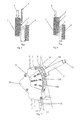
- FIG. 1 is a schematic illustration of an energy absorption system according to the prior art in the normal position.
- FIG. 2 is a schematic illustration of an energy absorption system according to the prior art after a force effect.
- FIG. 3 is a schematic illustration of an inventive energy absorption system with two sheets in the normal position.
- FIG. 4 is a schematic illustration of an inventive energy absorption system in which according to alternative (1) both sheets are decoupled from the movable carriage after a force effect.
- FIG. 5 is a schematic illustration of an inventive energy absorption system in which according to alternative (2) one sheet is coupled with the movable carriage after a force effect.
- FIG. 6 is a schematic illustration of an inventive energy absorption system in which according to alternative (3) both sheets are coupled with the movable carriage after a force effect.
- FIG. 7 is a cross-section through an inventive energy absorption system in the setting according to alternative (1).
- FIG. 8 is a cross-section through the coupling mechanism of an inventive energy absorption system in the setting according to alternative (2).
- FIG. 9 is a cross-section through the coupling mechanism of an inventive energy absorption system in the setting according to alternative (3).
- FIG. 10 is an exploded view of certain parts of the inventive energy absorption system.
- FIG. 11 is a perspective view of a lever mechanism for an inventive energy absorption system.
- FIG. 3 there is now shown an inventive energy absorption system.
- the latter comprises as already in the known system shown in FIGS. 1 and 2 a substantially U-shaped material strip 3 , which is screwed to the movable carriage 1 and which is areally connected to the fixed bearing 2 .
- the inventive energy absorption system comprises a first sheet 4 and a second sheet 5 , which in the illustrated normal condition abut at the movable carriage 1 and may—depending on the weight of the person which wants to sit down on the seat—be coupled with the latter. Thereby it is distinguished between three alternatives (1) to (3).
- the second sheet 5 is coupled with the movable carriage 1 (the functioning of the corresponding coupling mechanism is explained further below). Under the effect of the force F the movable carriage 1 is thus pressed downwards together with the second sheet 5 .
- the gap S being now formed between the movable carriage 1 (inclusive sheet 5 ) and the fixed bearing 2 comprises in this alternative a medium value (S med ).
- the gap S is reduced by the second sheet 5 being coupled to the movable carriage 1 , whereby also the bending of the substantially U-shaped material strip 3 gets stronger (i.e. the bending radius is smaller with regard to alternative (1)).
- the second sheet may abut during the downward movement of the movable carriage 1 at the shorter leg of the substantially U-shaped material strip and deform the latter, if applicable.
- the first sheet 4 and the second sheet 5 are coupled to the movable carriage 1 (the functioning of the corresponding coupling mechanism is explained further below). Under the effect of the force F the movable carriage 1 is thus pressed downwards together with the first sheet 4 and the second sheet 5 .
- the gap S being now formed between the movable carriage 1 (inclusive sheets 4 and 5 ) and the fixed bearing 2 comprises in this alternative a minimum value (S min ).
- the gap S is further reduced by means of the sheets 4 and 5 being coupled to the movable carriage 1 , whereby again the bending of the substantially U-shaped material strip 3 is enhanced (i.e. the bending radius is reduced with regard to alternative (2)).
- the first and/or second sheet 4 , 5 may during the downwards movement of the movable carriage 1 regularly abut at the shorter leg of the substantially U-shaped material strip 3 and deform the latter, if applicable.
- FIG. 7 illustrates a cross-section through an inventive energy absorption system and the substantial parts of the latter in the setting according to alternative (1).
- a frame element 6 is thereby fixed by means of two screws 7 , 8 at a mounting, whereby an intermediate element 9 is used.
- At the fixed bearing 2 there is areally (large scale) arranged the substantially U-shaped material strip 3 which is mounted at the movable carriage 1 by means of a screw 10 .
- the sheets 4 , 5 respectively comprise recesses respectively slots (cf. FIG. 10 ) for coupling with the movable carriage 1 .
- the movable carriage 1 comprises a first channel 11 and a second channel 12 for receiving a front part 131 , 141 of a first piston element 13 and of a second piston element 14 .
- the two piston elements 13 , 14 are thereby arranged in a connector housing 15 , which abuts at the movable carriage 1 .
- the second piston element 14 is formed cylindrically and encloses the first piston element 13 , such that the first piston element 13 is arranged within the second piston element 14 .
- the first piston element 13 is held by means of a first spring 16 within the connector housing 15 and the second piston element 14 is held within the connector housing 15 by means of the second spring 17 .
- the first piston element 13 abuts at a stopper 142 of the second piston element 14 .
- the first piston element 13 interacts with a bushing 18 , which protrudes through a bore 152 into the connector housing 15 .
- the shaft 130 of the first piston element 13 is thereby displaceably arranged within the bushing 18 .
- the bushing 18 abuts with the circumferential projection 180 onto the connector housing 15 .
- a bowden cable 19 Through the bushing 18 and the shaft 130 of the first piston element 13 runs a bowden cable 19 , which is anchored by means of a sphere 190 in a corresponding recess in the first piston element 13 .
- a support 21 is attached by means of a bolt 20 .
- a front part 141 of the second piston element 14 within the second channel 12 of the movable carriage 1 which is however not in engagement with one of the sheets 4 or 5 .
- the front part 131 of the first piston element 13 is fully located within the connector housing 15 .
- the first and the second piston element 13 , 14 have been brought against the force of the first and of the second spring 16 , 17 into a position via the bowden cable 19 , in which during the downward movement of the carriage 1 none of the sheets 4 , 5 is carried along. This leads to the gap S max which is illustrated in FIG. 4 .
- FIG. 8 illustrates the inventive coupling mechanism in the setting according to alternative (2).
- the front part 141 of the second piston element 14 passes through the second channel 12 of the movable carriage 1 and through the second sheet 5 and the first sheet 4 .
- the second sheet 5 comprises thereby a bore 50 (cf. FIG. 10 ) and the first sheet 4 comprises a slot 40 (cf. FIG. 10 ).
- the second piston element 14 is in engagement with the second sheet 5 , but not with the first sheet 4 .
- both piston elements 13 and 14 have been moved further out of the connector housing 15 .
- the front part 131 of the first piston element 13 has already been moved slightly into the first channel 11 of the movable carriage 1 ; it is however not yet into engagement with one of the sheets 4 or 5 .
- the actuation of the piston elements 13 , 14 occurs again via the lever mechanism according to FIG. 11 .
- Via the bowden cable 19 the first piston element 13 and the second piston element 14 are brought into position by means of the force of the first spring 16 and of the second spring 17 in which during a downward movement of the carriage 1 the second sheet 5 is coupled to the latter. This leads to the gap S med illustrated in FIG. 5 .
- FIG. 9 illustrates the inventive coupling mechanism in the position according to alternative (3).
- the front part 141 of the second piston element 14 passes through the second channel 12 of the movable carriage 1 as well as the front part 131 of the first piston element 13 through the first channel 11 of the movable carriage 1 .
- the front part 141 of the second piston element 14 passes in addition through the bore 50 of the second sheet 5 and through the slot 40 of the first sheet (cf. FIG. 10 ).
- the front part 131 of the first piston element 13 passes through the bore 51 of the second sheet 5 and through the bore 51 of the first sheet 4 .
- the piston elements 13 , 14 have, with regard to alternative (2) been still moved somewhat further out of the connector housing.
- FIG. 10 the fixed bearing 2 , the substantially U-shaped material strip 3 , the movable carriage 1 , the first and the second sheet 4 , 5 as well as the connector housing 15 are illustrated individually.
- the substantially U-shaped material strip 3 is thereby mounted at the movable carriage 1 by means of the screw 10 .
- the first sheet 4 is rippably mounted at the fixed bearing 3 by means of two screws 42 .
- the second sheet 5 is rippably mounted at the fixed bearing 2 by means of two screws 52 wherein in the first sheet 4 two recesses 43 for the screws 52 are provided.
- the connector housing 15 with the side parts 151 is mounted at the movable carriage 1 by means of two screws 150 .
- the first and the second piston elements 13 , 14 are arranged wherein respectively the front parts 131 , 141 are visible.
- the front part 141 of the second piston element 14 passes through the second channel 12 within the movable carriage 1 , the opening 50 in the second sheet 5 and through the slot 40 in the first sheet 4 .
- the front part 141 of the first piston element 13 passes through the channel 11 in the movable carriage 1 , the opening 51 in the second sheet and through the opening 41 in the first sheet 4 .
- FIG. 11 finally the inventive lever mechanism is shown.
- the latter consists of a housing 30 , a lever 31 with a push button 32 and a latching rail 33 having three latching stages 35 a , 35 b and 35 c .
- a scale 34 Beside the latching rail 33 there is arranged onto the housing 30 a scale 34 , which shows the weight ranges below 80 kg, between 80 and 97 kg as well as above 97 kg, which correspond with three latching stages 35 a , 35 b and 35 c .
- the bowden cable 19 which runs in the covering 36 to the first piston element 13 where it is anchored, may be actuated via a common mechanics.
- the shown lever setting in the latching stage 35 a corresponds to FIG. 7 (alternative (1)) in which both sheets 4 , 5 are decoupled from the movable carriage 1 .
- the springs 16 , 17 are biased and both piston elements 13 , 14 are positioned within the connector housing 15 ; only the front part 141 of the second piston element 14 protrudes slightly into the second channel 12 of the movable carriage 1 .
- the lever 31 is brought into the next latching stage 35 b .
Landscapes
- Engineering & Computer Science (AREA)
- Mechanical Engineering (AREA)
- Aviation & Aerospace Engineering (AREA)
- Transportation (AREA)
- General Engineering & Computer Science (AREA)
- Vibration Dampers (AREA)
Abstract
Description
- 1 movable carriage
- 2 fixed bearing
- 3 material strip
- 4 first sheet
- 5 second sheet
- 6 frame element
- 7 screw
- 8 screw
- 9 intermediate element
- 10 screw
- 11 first channel
- 12 second channel
- 13 first piston element
- 14 second piston element
- 15 connector housing
- 16 first spring
- 17 second spring
- 18 bushing
- 19 bowden cable
- 20 bolt
- 21 support
- 30 housing
- 31 lever
- 32 push button
- 33 latching rail
- 34 scale
- 35 a, b, c latching stages
- 36 covering
- 40 slot
- 41 opening
- 42 screws
- 43 recess
- 50 opening
- 51 opening
- 52 screws
- 130 shaft
- 131 front part
- 141 front part
- 150 screws
- 151 side parts
- 152 bore
- 180 projection
- Smax maximum gap
- Smed medium gap
- Smin minimum gap
Claims (12)
Applications Claiming Priority (3)
| Application Number | Priority Date | Filing Date | Title |
|---|---|---|---|
| DE102008017815 | 2008-04-08 | ||
| DE102008017815.2 | 2008-04-08 | ||
| DE102008017815A DE102008017815B4 (en) | 2008-04-08 | 2008-04-08 | Energy absorption system |
Publications (2)
| Publication Number | Publication Date |
|---|---|
| US20090250851A1 US20090250851A1 (en) | 2009-10-08 |
| US8550224B2 true US8550224B2 (en) | 2013-10-08 |
Family
ID=41132523
Family Applications (1)
| Application Number | Title | Priority Date | Filing Date |
|---|---|---|---|
| US12/420,186 Active 2030-01-07 US8550224B2 (en) | 2008-04-08 | 2009-04-08 | Energy absorption system |
Country Status (2)
| Country | Link |
|---|---|
| US (1) | US8550224B2 (en) |
| DE (1) | DE102008017815B4 (en) |
Cited By (6)
| Publication number | Priority date | Publication date | Assignee | Title |
|---|---|---|---|---|
| US20120073185A1 (en) * | 2009-06-02 | 2012-03-29 | Pekka Jokela | Method of carrying out pyrolysis and pyrolysis apparatus |
| RU2753774C1 (en) * | 2021-02-05 | 2021-08-23 | Общество с ограниченной ответственностью «ТУЛПАР ИНТЕРЬЕРЫ ИНЖИНИРИНГ ДИЗАЙН» | Energy absorbing system and helicopter seat containing energy absorbing system |
| EP4339103A1 (en) | 2022-09-19 | 2024-03-20 | AMI Industries, Inc. | Method for translating pins using a rotary actuator |
| US11945590B1 (en) | 2022-09-08 | 2024-04-02 | Ami Industries, Inc. | Aircraft seat with energy attenuating metering plate |
| US20240124144A1 (en) * | 2022-10-14 | 2024-04-18 | Ami Industries, Inc. | Offset helicopter pilot seat with singular energy absorber |
| US12122521B2 (en) | 2022-10-14 | 2024-10-22 | Ami Industries, Inc. | Offset helicopter pilot seat with centered vertical motion system |
Families Citing this family (3)
| Publication number | Priority date | Publication date | Assignee | Title |
|---|---|---|---|---|
| DE102008061609B4 (en) | 2008-12-11 | 2012-06-06 | Fischer Seats International Gmbh | Shot-proof seat shell and method of manufacture |
| DE102012103036A1 (en) | 2012-04-10 | 2013-10-10 | Krauss-Maffei Wegmann Gmbh & Co. Kg | Housing, especially against detonation protected vehicle housing |
| US9593740B2 (en) * | 2015-05-13 | 2017-03-14 | The Boeing Company | Energy-absorbing composite tension-shear fitting |
Citations (9)
| Publication number | Priority date | Publication date | Assignee | Title |
|---|---|---|---|---|
| US3146014A (en) * | 1959-08-12 | 1964-08-25 | Gen Motors Corp | Energy absorbing vehicle bumper assembly |
| US4054156A (en) * | 1975-02-24 | 1977-10-18 | The Weatherhead Company | Exhaust brake valve |
| FR2375499A1 (en) | 1976-12-27 | 1978-07-21 | Joye Jacques | Energy absorbing bumper for automobile - has U=shaped fixing strip and brazed attachment joint deformed by force of shock |
| US4901594A (en) * | 1988-02-19 | 1990-02-20 | Selzer Guenther | Gas spring assembly for a passenger seat control |
| US5211694A (en) * | 1989-06-20 | 1993-05-18 | Mazda Motor Corporation | Safety apparatus including an air bag and a safety belt supported on a vehicle with a deformable coupling |
| DE4134545C2 (en) | 1991-05-24 | 1994-03-31 | Thomas Dipl Ing Fischer | Energy absorption element |
| US6189929B1 (en) | 1999-11-02 | 2001-02-20 | Trw Inc. | Adaptive collapsible steering column |
| WO2005002676A1 (en) * | 2003-07-03 | 2005-01-13 | Keyguard Limited | Energy absorber |
| WO2007093283A1 (en) | 2006-02-15 | 2007-08-23 | Airbus Deutschland Gmbh | Force level control for an energy absorber for aircraft |
-
2008
- 2008-04-08 DE DE102008017815A patent/DE102008017815B4/en active Active
-
2009
- 2009-04-08 US US12/420,186 patent/US8550224B2/en active Active
Patent Citations (9)
| Publication number | Priority date | Publication date | Assignee | Title |
|---|---|---|---|---|
| US3146014A (en) * | 1959-08-12 | 1964-08-25 | Gen Motors Corp | Energy absorbing vehicle bumper assembly |
| US4054156A (en) * | 1975-02-24 | 1977-10-18 | The Weatherhead Company | Exhaust brake valve |
| FR2375499A1 (en) | 1976-12-27 | 1978-07-21 | Joye Jacques | Energy absorbing bumper for automobile - has U=shaped fixing strip and brazed attachment joint deformed by force of shock |
| US4901594A (en) * | 1988-02-19 | 1990-02-20 | Selzer Guenther | Gas spring assembly for a passenger seat control |
| US5211694A (en) * | 1989-06-20 | 1993-05-18 | Mazda Motor Corporation | Safety apparatus including an air bag and a safety belt supported on a vehicle with a deformable coupling |
| DE4134545C2 (en) | 1991-05-24 | 1994-03-31 | Thomas Dipl Ing Fischer | Energy absorption element |
| US6189929B1 (en) | 1999-11-02 | 2001-02-20 | Trw Inc. | Adaptive collapsible steering column |
| WO2005002676A1 (en) * | 2003-07-03 | 2005-01-13 | Keyguard Limited | Energy absorber |
| WO2007093283A1 (en) | 2006-02-15 | 2007-08-23 | Airbus Deutschland Gmbh | Force level control for an energy absorber for aircraft |
Cited By (10)
| Publication number | Priority date | Publication date | Assignee | Title |
|---|---|---|---|---|
| US20120073185A1 (en) * | 2009-06-02 | 2012-03-29 | Pekka Jokela | Method of carrying out pyrolysis and pyrolysis apparatus |
| US9045694B2 (en) * | 2009-06-02 | 2015-06-02 | Valmet Technologies Oy | Method of carrying out pyrolysis and pyrolysis apparatus |
| RU2753774C1 (en) * | 2021-02-05 | 2021-08-23 | Общество с ограниченной ответственностью «ТУЛПАР ИНТЕРЬЕРЫ ИНЖИНИРИНГ ДИЗАЙН» | Energy absorbing system and helicopter seat containing energy absorbing system |
| US11945590B1 (en) | 2022-09-08 | 2024-04-02 | Ami Industries, Inc. | Aircraft seat with energy attenuating metering plate |
| EP4339103A1 (en) | 2022-09-19 | 2024-03-20 | AMI Industries, Inc. | Method for translating pins using a rotary actuator |
| US20240092488A1 (en) * | 2022-09-19 | 2024-03-21 | Ami Industries, Inc. | Method for translating pins using a rotary actuator |
| US12330793B2 (en) * | 2022-09-19 | 2025-06-17 | Ami Industries, Inc. | Method for translating pins using a rotary actuator |
| US20240124144A1 (en) * | 2022-10-14 | 2024-04-18 | Ami Industries, Inc. | Offset helicopter pilot seat with singular energy absorber |
| US12122521B2 (en) | 2022-10-14 | 2024-10-22 | Ami Industries, Inc. | Offset helicopter pilot seat with centered vertical motion system |
| US12195187B2 (en) * | 2022-10-14 | 2025-01-14 | Ami Industries, Inc. | Offset helicopter pilot seat with singular energy absorber |
Also Published As
| Publication number | Publication date |
|---|---|
| DE102008017815A1 (en) | 2010-02-04 |
| DE102008017815B4 (en) | 2012-01-26 |
| US20090250851A1 (en) | 2009-10-08 |
Similar Documents
| Publication | Publication Date | Title |
|---|---|---|
| US8550224B2 (en) | Energy absorption system | |
| EP3519276B1 (en) | Steering assembly with positive lock and energy absorption and pyrotechnic actuator | |
| US20050088027A1 (en) | Cam-driven four-way head restraint assembly | |
| EP1880893B1 (en) | A base for fitting infant seats to motorcars | |
| EP3702208B1 (en) | Car safety seat | |
| US8840178B2 (en) | Seatback for vehicle seat | |
| CN101670796A (en) | child safety seat | |
| CN102785593A (en) | Locking device of seat rail of vehicle | |
| KR102613446B1 (en) | Seat track mechanism for vehicle seat | |
| EP3067275B1 (en) | A folding table arrangement for a vehicle seat back | |
| EP2394844A1 (en) | Seat suspension | |
| EP3626527B1 (en) | Extension assist for headrest | |
| EP4335745B1 (en) | Aircraft seat with energy attenuating metering plate | |
| US10471876B2 (en) | Foot support device of a motor vehicle | |
| CN117141324A (en) | Seating equipment and vehicles | |
| EP4339103B1 (en) | Method for translating pins using a rotary actuator | |
| US20050242647A1 (en) | Device for reclining seatback of vehicle | |
| WO2014125507A2 (en) | An internal bottom locking type sliding system | |
| EP4292877A1 (en) | Seat assembly | |
| WO2010002327A1 (en) | Whiplash protection arrangement | |
| US20220266889A1 (en) | Steering column telescope positive lock and breakaway device | |
| WO2006037284A3 (en) | Vehicle seat provided with an adjustable headrest | |
| CN109941172A (en) | Automotive seat and vehicle with headrest adjustable mechanism | |
| US20240278919A1 (en) | Reclining seat structure and methods thereof | |
| CN109927593A (en) | Child safety seat |
Legal Events
| Date | Code | Title | Description |
|---|---|---|---|
| AS | Assignment |
Owner name: FISCHER SEATS INTERNATIONAL GMBH, GERMANY Free format text: ASSIGNMENT OF ASSIGNORS INTEREST;ASSIGNOR:BAUER, ROLAND;REEL/FRAME:022733/0580 Effective date: 20090514 |
|
| STCF | Information on status: patent grant |
Free format text: PATENTED CASE |
|
| AS | Assignment |
Owner name: B/E AEROSPACE FISCHER GMBH, GERMANY Free format text: CHANGE OF NAME;ASSIGNOR:FISCHER SEATS INTERNATIONAL GMBH;REEL/FRAME:035298/0770 Effective date: 20141117 |
|
| FEPP | Fee payment procedure |
Free format text: PAYOR NUMBER ASSIGNED (ORIGINAL EVENT CODE: ASPN); ENTITY STATUS OF PATENT OWNER: LARGE ENTITY |
|
| FPAY | Fee payment |
Year of fee payment: 4 |
|
| FEPP | Fee payment procedure |
Free format text: ENTITY STATUS SET TO UNDISCOUNTED (ORIGINAL EVENT CODE: BIG.) |
|
| FEPP | Fee payment procedure |
Free format text: PETITION RELATED TO MAINTENANCE FEES GRANTED (ORIGINAL EVENT CODE: PTGR) |
|
| MAFP | Maintenance fee payment |
Free format text: PAYMENT OF MAINTENANCE FEE UNDER 1.28(C) (ORIGINAL EVENT CODE: M1559) |
|
| MAFP | Maintenance fee payment |
Free format text: PAYMENT OF MAINTENANCE FEE, 8TH YEAR, LARGE ENTITY (ORIGINAL EVENT CODE: M1552); ENTITY STATUS OF PATENT OWNER: LARGE ENTITY Year of fee payment: 8 |
|
| MAFP | Maintenance fee payment |
Free format text: PAYMENT OF MAINTENANCE FEE, 12TH YEAR, LARGE ENTITY (ORIGINAL EVENT CODE: M1553); ENTITY STATUS OF PATENT OWNER: LARGE ENTITY Year of fee payment: 12 |