US8538618B2 - Clutch control device of hybrid vehicle - Google Patents
Clutch control device of hybrid vehicle Download PDFInfo
- Publication number
- US8538618B2 US8538618B2 US13/269,181 US201113269181A US8538618B2 US 8538618 B2 US8538618 B2 US 8538618B2 US 201113269181 A US201113269181 A US 201113269181A US 8538618 B2 US8538618 B2 US 8538618B2
- Authority
- US
- United States
- Prior art keywords
- clutch
- engine
- shaft
- motor
- revolutions
- Prior art date
- Legal status (The legal status is an assumption and is not a legal conclusion. Google has not performed a legal analysis and makes no representation as to the accuracy of the status listed.)
- Expired - Fee Related, expires
Links
Images


Classifications
-
- B—PERFORMING OPERATIONS; TRANSPORTING
- B60—VEHICLES IN GENERAL
- B60W—CONJOINT CONTROL OF VEHICLE SUB-UNITS OF DIFFERENT TYPE OR DIFFERENT FUNCTION; CONTROL SYSTEMS SPECIALLY ADAPTED FOR HYBRID VEHICLES; ROAD VEHICLE DRIVE CONTROL SYSTEMS FOR PURPOSES NOT RELATED TO THE CONTROL OF A PARTICULAR SUB-UNIT
- B60W20/00—Control systems specially adapted for hybrid vehicles
- B60W20/40—Controlling the engagement or disengagement of prime movers, e.g. for transition between prime movers
-
- B—PERFORMING OPERATIONS; TRANSPORTING
- B60—VEHICLES IN GENERAL
- B60K—ARRANGEMENT OR MOUNTING OF PROPULSION UNITS OR OF TRANSMISSIONS IN VEHICLES; ARRANGEMENT OR MOUNTING OF PLURAL DIVERSE PRIME-MOVERS IN VEHICLES; AUXILIARY DRIVES FOR VEHICLES; INSTRUMENTATION OR DASHBOARDS FOR VEHICLES; ARRANGEMENTS IN CONNECTION WITH COOLING, AIR INTAKE, GAS EXHAUST OR FUEL SUPPLY OF PROPULSION UNITS IN VEHICLES
- B60K6/00—Arrangement or mounting of plural diverse prime-movers for mutual or common propulsion, e.g. hybrid propulsion systems comprising electric motors and internal combustion engines
- B60K6/20—Arrangement or mounting of plural diverse prime-movers for mutual or common propulsion, e.g. hybrid propulsion systems comprising electric motors and internal combustion engines the prime-movers consisting of electric motors and internal combustion engines, e.g. HEVs
- B60K6/42—Arrangement or mounting of plural diverse prime-movers for mutual or common propulsion, e.g. hybrid propulsion systems comprising electric motors and internal combustion engines the prime-movers consisting of electric motors and internal combustion engines, e.g. HEVs characterised by the architecture of the hybrid electric vehicle
- B60K6/44—Series-parallel type
- B60K6/442—Series-parallel switching type
-
- B—PERFORMING OPERATIONS; TRANSPORTING
- B60—VEHICLES IN GENERAL
- B60W—CONJOINT CONTROL OF VEHICLE SUB-UNITS OF DIFFERENT TYPE OR DIFFERENT FUNCTION; CONTROL SYSTEMS SPECIALLY ADAPTED FOR HYBRID VEHICLES; ROAD VEHICLE DRIVE CONTROL SYSTEMS FOR PURPOSES NOT RELATED TO THE CONTROL OF A PARTICULAR SUB-UNIT
- B60W10/00—Conjoint control of vehicle sub-units of different type or different function
- B60W10/02—Conjoint control of vehicle sub-units of different type or different function including control of driveline clutches
-
- B—PERFORMING OPERATIONS; TRANSPORTING
- B60—VEHICLES IN GENERAL
- B60W—CONJOINT CONTROL OF VEHICLE SUB-UNITS OF DIFFERENT TYPE OR DIFFERENT FUNCTION; CONTROL SYSTEMS SPECIALLY ADAPTED FOR HYBRID VEHICLES; ROAD VEHICLE DRIVE CONTROL SYSTEMS FOR PURPOSES NOT RELATED TO THE CONTROL OF A PARTICULAR SUB-UNIT
- B60W10/00—Conjoint control of vehicle sub-units of different type or different function
- B60W10/04—Conjoint control of vehicle sub-units of different type or different function including control of propulsion units
- B60W10/06—Conjoint control of vehicle sub-units of different type or different function including control of propulsion units including control of combustion engines
-
- B—PERFORMING OPERATIONS; TRANSPORTING
- B60—VEHICLES IN GENERAL
- B60W—CONJOINT CONTROL OF VEHICLE SUB-UNITS OF DIFFERENT TYPE OR DIFFERENT FUNCTION; CONTROL SYSTEMS SPECIALLY ADAPTED FOR HYBRID VEHICLES; ROAD VEHICLE DRIVE CONTROL SYSTEMS FOR PURPOSES NOT RELATED TO THE CONTROL OF A PARTICULAR SUB-UNIT
- B60W10/00—Conjoint control of vehicle sub-units of different type or different function
- B60W10/04—Conjoint control of vehicle sub-units of different type or different function including control of propulsion units
- B60W10/08—Conjoint control of vehicle sub-units of different type or different function including control of propulsion units including control of electric propulsion units, e.g. motors or generators
-
- B—PERFORMING OPERATIONS; TRANSPORTING
- B60—VEHICLES IN GENERAL
- B60W—CONJOINT CONTROL OF VEHICLE SUB-UNITS OF DIFFERENT TYPE OR DIFFERENT FUNCTION; CONTROL SYSTEMS SPECIALLY ADAPTED FOR HYBRID VEHICLES; ROAD VEHICLE DRIVE CONTROL SYSTEMS FOR PURPOSES NOT RELATED TO THE CONTROL OF A PARTICULAR SUB-UNIT
- B60W20/00—Control systems specially adapted for hybrid vehicles
-
- B—PERFORMING OPERATIONS; TRANSPORTING
- B60—VEHICLES IN GENERAL
- B60W—CONJOINT CONTROL OF VEHICLE SUB-UNITS OF DIFFERENT TYPE OR DIFFERENT FUNCTION; CONTROL SYSTEMS SPECIALLY ADAPTED FOR HYBRID VEHICLES; ROAD VEHICLE DRIVE CONTROL SYSTEMS FOR PURPOSES NOT RELATED TO THE CONTROL OF A PARTICULAR SUB-UNIT
- B60W50/00—Details of control systems for road vehicle drive control not related to the control of a particular sub-unit, e.g. process diagnostic or vehicle driver interfaces
- B60W50/02—Ensuring safety in case of control system failures, e.g. by diagnosing, circumventing or fixing failures
- B60W50/0205—Diagnosing or detecting failures; Failure detection models
-
- B—PERFORMING OPERATIONS; TRANSPORTING
- B60—VEHICLES IN GENERAL
- B60W—CONJOINT CONTROL OF VEHICLE SUB-UNITS OF DIFFERENT TYPE OR DIFFERENT FUNCTION; CONTROL SYSTEMS SPECIALLY ADAPTED FOR HYBRID VEHICLES; ROAD VEHICLE DRIVE CONTROL SYSTEMS FOR PURPOSES NOT RELATED TO THE CONTROL OF A PARTICULAR SUB-UNIT
- B60W2510/00—Input parameters relating to a particular sub-units
- B60W2510/02—Clutches
- B60W2510/0208—Clutch engagement state, e.g. engaged or disengaged
-
- B—PERFORMING OPERATIONS; TRANSPORTING
- B60—VEHICLES IN GENERAL
- B60W—CONJOINT CONTROL OF VEHICLE SUB-UNITS OF DIFFERENT TYPE OR DIFFERENT FUNCTION; CONTROL SYSTEMS SPECIALLY ADAPTED FOR HYBRID VEHICLES; ROAD VEHICLE DRIVE CONTROL SYSTEMS FOR PURPOSES NOT RELATED TO THE CONTROL OF A PARTICULAR SUB-UNIT
- B60W2510/00—Input parameters relating to a particular sub-units
- B60W2510/06—Combustion engines, Gas turbines
- B60W2510/0638—Engine speed
-
- B—PERFORMING OPERATIONS; TRANSPORTING
- B60—VEHICLES IN GENERAL
- B60W—CONJOINT CONTROL OF VEHICLE SUB-UNITS OF DIFFERENT TYPE OR DIFFERENT FUNCTION; CONTROL SYSTEMS SPECIALLY ADAPTED FOR HYBRID VEHICLES; ROAD VEHICLE DRIVE CONTROL SYSTEMS FOR PURPOSES NOT RELATED TO THE CONTROL OF A PARTICULAR SUB-UNIT
- B60W2510/00—Input parameters relating to a particular sub-units
- B60W2510/06—Combustion engines, Gas turbines
- B60W2510/0676—Engine temperature
-
- B—PERFORMING OPERATIONS; TRANSPORTING
- B60—VEHICLES IN GENERAL
- B60W—CONJOINT CONTROL OF VEHICLE SUB-UNITS OF DIFFERENT TYPE OR DIFFERENT FUNCTION; CONTROL SYSTEMS SPECIALLY ADAPTED FOR HYBRID VEHICLES; ROAD VEHICLE DRIVE CONTROL SYSTEMS FOR PURPOSES NOT RELATED TO THE CONTROL OF A PARTICULAR SUB-UNIT
- B60W2510/00—Input parameters relating to a particular sub-units
- B60W2510/08—Electric propulsion units
- B60W2510/081—Speed
-
- B—PERFORMING OPERATIONS; TRANSPORTING
- B60—VEHICLES IN GENERAL
- B60W—CONJOINT CONTROL OF VEHICLE SUB-UNITS OF DIFFERENT TYPE OR DIFFERENT FUNCTION; CONTROL SYSTEMS SPECIALLY ADAPTED FOR HYBRID VEHICLES; ROAD VEHICLE DRIVE CONTROL SYSTEMS FOR PURPOSES NOT RELATED TO THE CONTROL OF A PARTICULAR SUB-UNIT
- B60W2520/00—Input parameters relating to overall vehicle dynamics
- B60W2520/10—Longitudinal speed
-
- Y—GENERAL TAGGING OF NEW TECHNOLOGICAL DEVELOPMENTS; GENERAL TAGGING OF CROSS-SECTIONAL TECHNOLOGIES SPANNING OVER SEVERAL SECTIONS OF THE IPC; TECHNICAL SUBJECTS COVERED BY FORMER USPC CROSS-REFERENCE ART COLLECTIONS [XRACs] AND DIGESTS
- Y02—TECHNOLOGIES OR APPLICATIONS FOR MITIGATION OR ADAPTATION AGAINST CLIMATE CHANGE
- Y02T—CLIMATE CHANGE MITIGATION TECHNOLOGIES RELATED TO TRANSPORTATION
- Y02T10/00—Road transport of goods or passengers
- Y02T10/60—Other road transportation technologies with climate change mitigation effect
- Y02T10/62—Hybrid vehicles
Definitions
- the present invention relates to a clutch control device of a hybrid vehicle.
- a hybrid vehicle equipped with an engine and a motor has various driving modes including an EV driving mode, a series driving mode, and a parallel driving mode.
- such hybrid vehicle includes a clutch 35 that engages/releases an engine shaft 32 at an engine 31 side with/from a motor shaft 34 at a motor 33 side, and the hybrid vehicle maintains the clutch 35 in an engaged state/a released state based on the driving mode (see, for example, Japanese Patent No. 3702897B).
- Any one of a wet type (single plate/multi-plates) and a dry type (single plate/multi-plates) may be used as the clutch.
- both types will be referred to as the clutch.
- a tire 36 of a vehicle 30 is driven by driving the motor 33 , as shown in FIG. 8 .
- the engine 31 stops, electric generation by a generator 37 also stops, and the clutch 35 is in the released state.
- the tire 36 of the vehicle 30 is driven by driving the engine 31 , and the clutch 35 is in the engaged state.
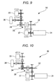
- the driving force of the engine 31 is transmitted to the motor shaft 34 side (drive shaft side), as shown in FIG. 10 .
- the tire 36 of the vehicle 30 may be driven by driving both the engine 31 and the motor 33 .
- the vehicle 30 is driven while the clutch 35 is released and the engine shaft 32 and the motor shaft 34 are in a mechanical power-off state, in the EV driving mode and the series driving mode in which the motor 33 is used as a driving force.
- the vehicle 30 is driven while the clutch 35 is engaged and the engine shaft 32 and the motor shaft 34 are mechanically coupled to each other.
- the clutch 35 having been released is engaged, whereas when the driving mode is switched from the parallel driving mode to the EV driving mode or the series driving mode, the clutch 35 having been engaged is released.
- the driving force shifts from the engine 31 to the motor 33 by releasing the clutch 35 having been engaged.
- an operation of the clutch 35 is performed by a clutch pressure sensor (not shown), but when the clutch pressure sensor is defective, the state of the operation of the clutch 35 cannot be determined thereby causing a secondary defect.
- a clutch control device of a hybrid vehicle comprising: a clutch which engages a motor shaft driven by a motor and connected with a drive shaft and an engine shaft driven by an engine with each other, the clutch which releases the motor shaft and the engine shaft from each other; a hydraulic unit which controls the clutch by an oil pressure of an oil; an oil temperature detecting unit which detects an oil temperature of the oil; a vehicle velocity detecting unit which detects a vehicle velocity of the hybrid vehicle; and a control unit which switches a driving mode between an engine driving mode in which the motor shaft and the engine shaft are engaged with each other and the hybrid vehicle is driven by the engine and a motor driving mode in which the motor shaft and the engine shaft are released from each other and the hybrid vehicle is driven by the motor, by controlling the clutch through the hydraulic unit, the control unit which, when the driving mode is switched from the engine driving mode to the motor driving mode, acquires a response time in which a state of the clutch is changed from an engaged state to a released state based on the
- FIG. 1 is a configuration diagram of a vehicle having a clutch control device of a hybrid vehicle according to the present invention.
- FIG. 2 is a graph illustrating a hydraulic characteristic of a hydraulic control valve.
- FIG. 3 is a graph illustrating a hydraulic responsiveness of the hydraulic control valve.
- FIG. 4 is a flowchart illustrating the control in the clutch control device of the hybrid vehicle according to the present invention.
- FIG. 5 is a block diagram when a clutch releasing time is calculated in the clutch control device of the hybrid vehicle according to the present invention.
- FIG. 6 is a flowchart illustrating another control in a clutch control device of a hybrid vehicle according to the present invention.
- FIG. 7 is a diagram illustrating a difference revolution control in the flowchart shown in FIG. 6 .
- FIG. 8 is a schematic diagram illustrating an EV driving mode in a hybrid vehicle.
- FIG. 9 is a schematic diagram illustrating a series driving mode in the hybrid vehicle.
- FIG. 10 is a schematic diagram illustrating a parallel driving mode in the hybrid vehicle.
- FIG. 1 is a configuration diagram of a vehicle having a clutch control device of a hybrid vehicle according to the present invention.
- FIG. 2 is a graph illustrating a hydraulic characteristic of a hydraulic control valve
- FIG. 3 is a graph illustrating hydraulic responsiveness of the hydraulic control valve.
- FIGS. 4 and 5 are drawings illustrating control in the clutch control device of the hybrid vehicle of the present invention.
- FIG. 4 is a flowchart illustrating the control
- FIG. 5 is a block diagram when a clutch releasing time is calculated.
- a vehicle 10 is a hybrid vehicle using an engine 11 and a motor 15 as a power source, as shown in FIG. 1 .
- the vehicle 10 includes the engine 11 serving as the power source for electric generation while driving the vehicle, a generator 12 driven by the engine 11 to generate electricity, a high-voltage battery 13 charging electricity generated by the generator 12 , and a motor 15 receiving electricity from the generator 12 and the high-voltage battery 13 through an inverter 14 and using at least one of the electricity generated by the generator 12 and the electricity charged in the high-voltage battery 13 , to drive the vehicle 10 .
- the motor 15 drives a drive shaft of a front wheel 18 and is connected with the drive shaft of the front wheel 18 through a gear box (transmission) 17 (specifically, through a differential in the gear box 17 ).
- the engine 11 is also connected with the front wheel 18 through the gear box 17 , but connected with the front wheel 18 through a clutch 16 (further, through the differential in the gear box 17 ) installed in the gear box 17 when driving the drive shaft of the front wheel 18 .
- the clutch 16 is controlled by a hydraulic control valve (a hydraulic unit; not shown) such as a solenoid and specifically, engages/releases an engine shaft (see an engine shaft 25 in FIG. 7 to be described below) of the engine 11 and a motor shaft (see a motor shaft 26 in FIG.
- the clutch 16 may be separated from the gear box 17 and further, any one of a wet type (single/multi-plates) and a dry type (single/multi-plates) may be used as the clutch 16 .
- the motor 15 is installed at the front wheel 18 side, but a motor driving a rear wheel 19 may be further installed.
- a hybrid vehicle in which the engine 11 is driven and electricity is generated by the generator 12 to charge the generated electricity in the high-voltage battery 13 is exemplified, but a plug-in hybrid vehicle in which the high-voltage battery 13 can be charged from a household power supply or a quick charger outside the vehicle may be used.
- the vehicle 10 includes an engine electronics control unit (ECU) 21 controlling the engine 11 , a generator ECU 22 controlling the generator 12 , and an EV-ECU (vehicle integrated controller, a control unit) 23 controlling the high-voltage battery 13 , the motor 15 , and the gear box 17 (the clutch 16 ).
- the high-voltage battery 13 is connected with the EV-ECU 23 through a battery management unit (BMU) 24 managing the high-voltage battery 13 .
- the BMU 24 monitors voltage, current, temperature, and state of charge (SOC) of the high-voltage battery 13 and calculates a possible battery output based on the temperature and the SOC and notifies the voltage, the current, the temperature, and the SOC to the EV-ECU 23 .
- SOC state of charge
- the engine ECU 21 , the generator ECU 22 , and the EV-ECU 23 can transmit and receive information to and from each other by using, for example, a controller area network (CAN).
- CAN controller area network
- the EV-ECU 23 controls the clutch 16 , depending on the vehicle velocity and required driving force of the vehicle 10 , to switch the EV driving in which the battery is used, the series driving in which the combination of the battery and the engine is used, and the parallel driving in which the engine is used, by performing the clutch control to be described below.
- the EV-ECU 23 detects the vehicle velocity of the vehicle 10 from a vehicle velocity sensor (a vehicle velocity detecting unit, not shown) and acquires the required driving force based on an opening degree of an accelerator detected from an accelerator pedal (not shown).
- the EV-ECU detects an oil temperature of clutch oil of the clutch 16 from an oil temperature sensor (an oil temperature detecting unit, not shown) of the clutch 16 and individually detects the number of revolutions of the engine shaft (the engine shaft 25 of FIG. 7 ) of the engine 11 and the number of revolutions of the motor shaft (the motor shaft 26 of FIG. 7 ) of the motor 15 from a plurality of independent revolution sensors (a motor shaft revolution detecting unit and an engine shaft revolution detecting unit, not shown).
- the hydraulic control valve (a solenoid valve) controlling the engaging/releasing of the clutch 16 has a hydraulic characteristic that monotonically increases substantially in proportion to a control current from the EV-ECU 23 , as shown in the graph of FIG. 2 and the EV-ECU 23 controls the hydraulic control valve by controlling the control current depending on the hydraulic characteristic.
- a mechanical delay time is generated in the hydraulic control valve, a delay time is generated even in a change of the hydraulic pressure supplied to the clutch 16 , and a delay time is generated even in responsiveness of the clutch 16 .
- the delay time is generated in the change of the hydraulic pressure supplied to the clutch 16 , and as a result, a response time represented by a clutch releasing time Ta is required until the clutch 16 having been engaged is fully released, as shown in the graph of FIG. 3 . Therefore, when a predetermined response time is set, even though the clutch pressure sensor is defective, a secondary defect can be prevented from occurring.
- the clutch releasing time Ta depends on the vehicle velocity and the oil temperature of the clutch, as described in FIG. 5 to be described below, the secondary defect cannot be fully prevented from occurring only by setting the predetermined response time.
- the clutch control to be described below is performed based on the flowchart shown in FIG. 4 and the block diagram shown in FIG. 5 .
- a control sequence in the EV-ECU 23 will be described according to the flowchart of FIG. 4 .
- a clutch releasing flag is ON. Since the clutch 16 is in a released state and a vehicle is in the EV driving or the series driving, a series of control sequences are terminated, and when the clutch releasing flag is not ON, since the clutch 16 is in an engaged state and the vehicle is in parallel driving, the process proceeds to step S 2 .
- the parallel driving is terminated. For example, when the vehicle velocity of the vehicle 10 becomes a velocity at which the driving mode is changed from the parallel driving to the EV driving or the series driving, the parallel driving is terminated.
- the process proceeds to step S 3 , and when the parallel driving is not terminated, the series of control sequences are terminated.
- the clutch releasing control current flows to the hydraulic control valve from the EV-ECU 23 , and the process proceeds to step S 4 .
- the clutch releasing time Ta (the response time) is calculated by an estimation time map.
- a first estimation time T 1 for a vehicle velocity d 1 is acquired from an estimation time map for the vehicle velocity in a first calculating unit B 1
- a second estimation time T 2 for an oil temperature d 2 of the clutch 16 is acquired from an estimation time map for the oil temperature in a second calculation unit B 2
- the larger one of the first estimation time T 1 and the second estimation time T 2 is set to the clutch releasing time Ta in a third calculation unit B 3 , as shown in FIG. 5 .
- the estimation time for the vehicle velocity tends to decrease in inverse proportion to the increase of the vehicle velocity until a predetermined vehicle velocity and tends to be constant after the predetermined vehicle velocity, as shown in the map of the first calculation unit B 1 .
- the estimation time for the oil temperature tends to decrease substantially in inverse proportion to the increase of the oil temperature until a predetermined oil temperature and tends to increase substantially in proportion to the increase of the oil temperature after the predetermined oil temperature, as shown in the map of the second calculation unit B 2 .
- the clutch releasing time Ta is acquired by the vehicle velocity of the vehicle 10 and the oil temperature of the clutch 16 , and after the calculation of the clutch releasing time Ta, the process proceeds to step S 5 .
- the clutch releasing flag is ON.
- a subsequent control that is, the controls in the EV driving and the series driving are permitted and executed.
- the clutch releasing time Ta is acquired from the vehicle velocity of the vehicle 10 and the oil temperature of the clutch 16 , and after the acquired clutch releasing time Ta elapses, that is, after the time when the clutch 16 having been engaged is fully released elapses, the subsequent control is permitted, such that even though the clutch pressure sensor is defective, the secondary defect can be prevented from occurring.
- FIGS. 6 and 7 are diagrams illustrating another control in a clutch control device of a hybrid vehicle according to the present invention.
- FIG. 6 is a flowchart illustrating the control and
- FIG. 7 is a diagram illustrating a difference revolution control.
- the clutch control to be described below is performed based on the flowchart shown in FIG. 6 and the diagram shown in FIG. 7 .
- the clutch control device of the hybrid vehicle according to the second exemplary embodiment may have the same configuration as the clutch control device of the hybrid vehicle according to the first exemplary embodiment shown in FIG. 1 .
- the flowchart of FIG. 6 is the same as the flowchart of FIG. 4 according to the first exemplary embodiment except for control sequences of steps SP 1 to SP 3 inserted between steps S 5 and S 6 . Therefore, herein, a duplicated description is omitted or simplified.
- a clutch releasing flag is ON.
- a series of control sequences are terminated, and when the clutch releasing flag is not ON, the process proceeds to step S 2 .
- the clutch releasing control current flows to the hydraulic control valve from the EV-ECU 23 , and the process proceeds to step S 4 .
- a clutch releasing time Ta is calculated by an estimation time map, and after the calculation, the process proceeds to step S 5 .
- An elapsed time T passes the clutch releasing time Ta, and thereafter, the process proceeds to step SP 1 .
- the clutch releasing time Ta may be provided to obtain a start timing of the difference revolution control in the next step SP 1 .
- the difference revolution control is performed in order to check whether or not the motor shaft and the engine shaft are mechanically powered off.
- the difference revolution control will be described below with reference to FIG. 7 .
- the difference revolution control while the motor shaft 26 is rotated at a target number of revolutions of the motor shaft Nmt [rpm] that is required for the driving by controlling the motor 15 , the engine shaft 25 is rotated at a target number of revolutions of the engine shaft Net [rpm] that is different from the target number of revolutions of the motor shaft Nmt by a predetermined number of revolutions (for example, 100 rpm) by controlling the engine 11 .
- the target number of revolutions of the engine shaft Net is set to a number of revolutions acquired by subtracting a difference number of revolutions Na [rpm] from the target number of revolutions of the motor shaft Nmt so as to be different from the target number of revolutions of the motor shaft Nmt.
- the target number of revolutions of the engine shaft Net set in the difference revolution control may be set to a deceleration side in order to prevent a rapid acceleration of the vehicle 10 , taking into consideration of the case where the clutch 16 is defective.
- the number of revolutions of the motor shaft Nm is not equal to the target number of revolutions of the motor shaft Nmt
- the number of revolutions of the engine shaft Ne is not equal to the target number of revolutions of the engine shaft Net.
- the number of revolutions of the motor shaft Nm and the number of revolutions of the engine shaft Ne become to be synchronized with each other, so that the number of revolutions of the motor shaft Nm and the number of revolutions of the engine shaft Ne cannot meet Equation 1.
- Equation 1 when Equation 1 is not met, it may be determined that the clutch 16 is in the engaged state (or in a half-clutch) which is the defective state, and the clutch releasing flag is not ON in the EV-ECU 23 .
- the subsequent controls that is, the controls in the EV driving and the series driving, a secondary defect can be prevented from occurring.
- the clutch releasing time Ta is acquired from the vehicle velocity of the vehicle 10 and the oil temperature of the clutch 16 , and after the acquired clutch releasing time Ta elapses, the difference revolution control is performed and it is determined whether or not the clutch 16 is defective. Since it is determined whether or not the subsequent controls are permitted or refused based on the result of the determination, even though a clutch pressure sensor is defective, the secondary defect can be prevented from occurring. Further, since the defect of the clutch 16 is determined, the defect of the clutch 16 can also be notified based on the result of the determination.
- the present invention is suitable for a hybrid vehicle.
Landscapes
- Engineering & Computer Science (AREA)
- Chemical & Material Sciences (AREA)
- Combustion & Propulsion (AREA)
- Transportation (AREA)
- Mechanical Engineering (AREA)
- Automation & Control Theory (AREA)
- Human Computer Interaction (AREA)
- Hybrid Electric Vehicles (AREA)
- Hydraulic Clutches, Magnetic Clutches, Fluid Clutches, And Fluid Joints (AREA)
- Electric Propulsion And Braking For Vehicles (AREA)
- Control Of Vehicle Engines Or Engines For Specific Uses (AREA)
Abstract
Description
|Number of revolutions of Motor shaft Nm−Number of revolutions of Engine shaft Ne|≧Difference number of
Claims (4)
Applications Claiming Priority (2)
| Application Number | Priority Date | Filing Date | Title |
|---|---|---|---|
| JP2010-228057 | 2010-10-08 | ||
| JP2010228057A JP5201191B2 (en) | 2010-10-08 | 2010-10-08 | Hybrid vehicle clutch control device |
Publications (2)
| Publication Number | Publication Date |
|---|---|
| US20120089285A1 US20120089285A1 (en) | 2012-04-12 |
| US8538618B2 true US8538618B2 (en) | 2013-09-17 |
Family
ID=45044313
Family Applications (1)
| Application Number | Title | Priority Date | Filing Date |
|---|---|---|---|
| US13/269,181 Expired - Fee Related US8538618B2 (en) | 2010-10-08 | 2011-10-07 | Clutch control device of hybrid vehicle |
Country Status (4)
| Country | Link |
|---|---|
| US (1) | US8538618B2 (en) |
| EP (1) | EP2439118B1 (en) |
| JP (1) | JP5201191B2 (en) |
| CN (1) | CN102442305B (en) |
Cited By (3)
| Publication number | Priority date | Publication date | Assignee | Title |
|---|---|---|---|---|
| US20130274976A1 (en) * | 2010-10-22 | 2013-10-17 | Hino Motors, Ltd. | Vehicle, control method, and computer program |
| US20140162840A1 (en) * | 2012-12-07 | 2014-06-12 | Kia Motors Corporation | Method and system for controlling anti-jerk of hybrid electric vehicle |
| US20150360572A1 (en) * | 2014-06-13 | 2015-12-17 | Mitsubishi Jidosha Engineering Kabushiki Kaisha | Electric vehicle |
Families Citing this family (12)
| Publication number | Priority date | Publication date | Assignee | Title |
|---|---|---|---|---|
| JP5892315B2 (en) * | 2011-12-13 | 2016-03-23 | 三菱自動車工業株式会社 | Clutch control device for hybrid vehicle |
| JP2014105851A (en) * | 2012-11-30 | 2014-06-09 | Toyota Motor Corp | Travelling control device of vehicle |
| JP5618105B2 (en) * | 2013-01-09 | 2014-11-05 | 三菱自動車工業株式会社 | Control device for hybrid vehicle |
| US9415772B2 (en) * | 2013-03-14 | 2016-08-16 | Textron Innovations Inc. | Rear drive module for a vehicle |
| EP2990282B1 (en) * | 2013-04-26 | 2018-02-21 | Nissan Motor Co., Ltd. | Clutch control device for hybrid vehicle |
| JP6079521B2 (en) * | 2013-09-13 | 2017-02-15 | 日産自動車株式会社 | Hybrid vehicle |
| CN103465899B (en) * | 2013-09-23 | 2016-06-29 | 湖南南车时代电动汽车股份有限公司 | A kind of series-parallel connection car engine starts and controls system and method |
| RU2638342C2 (en) * | 2013-09-30 | 2017-12-13 | Ниссан Мотор Ко., Лтд. | Device and method for hybrid vehicle control |
| JP6156243B2 (en) * | 2014-04-16 | 2017-07-05 | トヨタ自動車株式会社 | Control device for hybrid vehicle |
| CN110861596B (en) * | 2018-08-27 | 2021-04-06 | 广州汽车集团股份有限公司 | Method, device, control device and storage medium for main oil pressure regulation |
| CN111156265B (en) * | 2019-12-25 | 2021-09-28 | 中国第一汽车股份有限公司 | Method and device for determining clutch pressure, vehicle and storage medium |
| CN115416640B (en) * | 2022-09-21 | 2025-09-09 | 中国第一汽车股份有限公司 | Vehicle and control method and device thereof |
Citations (15)
| Publication number | Priority date | Publication date | Assignee | Title |
|---|---|---|---|---|
| US6223842B1 (en) * | 1998-05-18 | 2001-05-01 | Hitachi, Ltd. | Hybrid vehicle |
| JP3702897B2 (en) | 2004-05-24 | 2005-10-05 | 日産自動車株式会社 | Control device for hybrid vehicle |
| US20050256625A1 (en) | 2004-05-15 | 2005-11-17 | Sah Jy-Jen F | Hydraulic clutch state diagnostic and control |
| US20070202989A1 (en) * | 2006-02-27 | 2007-08-30 | Ford Global Technologies, Llc | Control method for cooling a launch clutch and an electric motor in a hybrid electric vehicle powertrain |
| US20070275823A1 (en) * | 2006-05-26 | 2007-11-29 | Nissan Motor Co., Ltd. | Clutch engagement control apparatus for hybrid vehicle |
| JP2008002687A (en) | 2007-09-25 | 2008-01-10 | Fujitsu Ten Ltd | Control device for continuously variable transmission |
| EP1894805A2 (en) | 2006-08-29 | 2008-03-05 | Nissan Motor Co., Ltd. | Hybrid vehicle control apparatus |
| JP2008120224A (en) | 2006-11-10 | 2008-05-29 | Nissan Motor Co Ltd | Vehicle control device |
| EP1950461A2 (en) | 2007-01-29 | 2008-07-30 | Toyota Jidosha Kabushiki Kaisha | Clutch engaged state determination apparatus and method thereof, gear determination apparatus and shift indication apparatus |
| JP2008303918A (en) | 2007-06-05 | 2008-12-18 | Toyota Motor Corp | Hydraulic oil cooling device for automatic transmission |
| US20090118083A1 (en) * | 2007-11-04 | 2009-05-07 | Gm Global Technology Operations, Inc. | Method and apparatus to control engine torque to peak main pressure for a hybrid powertrain system |
| US20090156355A1 (en) * | 2007-12-13 | 2009-06-18 | Hyundai Motor Company | System and method for controlling clutch engagement in hybrid vehicle |
| WO2009139305A1 (en) | 2008-05-14 | 2009-11-19 | 本田技研工業株式会社 | Vehicle control device |
| JP2010188776A (en) | 2009-02-16 | 2010-09-02 | Nissan Motor Co Ltd | Controller for hybrid vehicle |
| US7988592B2 (en) * | 2007-09-05 | 2011-08-02 | Hyundai Motor Company | Method for controlling idle stop mode in hybrid electric vehicle |
Family Cites Families (4)
| Publication number | Priority date | Publication date | Assignee | Title |
|---|---|---|---|---|
| JP3322072B2 (en) * | 1994-08-12 | 2002-09-09 | トヨタ自動車株式会社 | Power transmission lubrication system |
| JP3424562B2 (en) * | 1998-09-16 | 2003-07-07 | 日産自動車株式会社 | Transmission control device for automatic transmission |
| JP4218129B2 (en) * | 1999-05-24 | 2009-02-04 | アイシン・エィ・ダブリュ株式会社 | Hydraulic pressure generator and hybrid vehicle using the same |
| JP5187111B2 (en) * | 2008-10-06 | 2013-04-24 | トヨタ自動車株式会社 | Vehicle drive control device |
-
2010
- 2010-10-08 JP JP2010228057A patent/JP5201191B2/en not_active Expired - Fee Related
-
2011
- 2011-10-07 EP EP11184375.1A patent/EP2439118B1/en not_active Not-in-force
- 2011-10-07 US US13/269,181 patent/US8538618B2/en not_active Expired - Fee Related
- 2011-10-08 CN CN201110296862.XA patent/CN102442305B/en not_active Expired - Fee Related
Patent Citations (16)
| Publication number | Priority date | Publication date | Assignee | Title |
|---|---|---|---|---|
| US6223842B1 (en) * | 1998-05-18 | 2001-05-01 | Hitachi, Ltd. | Hybrid vehicle |
| US20050256625A1 (en) | 2004-05-15 | 2005-11-17 | Sah Jy-Jen F | Hydraulic clutch state diagnostic and control |
| JP3702897B2 (en) | 2004-05-24 | 2005-10-05 | 日産自動車株式会社 | Control device for hybrid vehicle |
| US20070202989A1 (en) * | 2006-02-27 | 2007-08-30 | Ford Global Technologies, Llc | Control method for cooling a launch clutch and an electric motor in a hybrid electric vehicle powertrain |
| US20070275823A1 (en) * | 2006-05-26 | 2007-11-29 | Nissan Motor Co., Ltd. | Clutch engagement control apparatus for hybrid vehicle |
| EP1894805A2 (en) | 2006-08-29 | 2008-03-05 | Nissan Motor Co., Ltd. | Hybrid vehicle control apparatus |
| JP2008120224A (en) | 2006-11-10 | 2008-05-29 | Nissan Motor Co Ltd | Vehicle control device |
| EP1950461A2 (en) | 2007-01-29 | 2008-07-30 | Toyota Jidosha Kabushiki Kaisha | Clutch engaged state determination apparatus and method thereof, gear determination apparatus and shift indication apparatus |
| JP2008185081A (en) | 2007-01-29 | 2008-08-14 | Toyota Motor Corp | Clutch engaged / disengaged state detection device, shift speed detection device, and shift instruction device |
| JP2008303918A (en) | 2007-06-05 | 2008-12-18 | Toyota Motor Corp | Hydraulic oil cooling device for automatic transmission |
| US7988592B2 (en) * | 2007-09-05 | 2011-08-02 | Hyundai Motor Company | Method for controlling idle stop mode in hybrid electric vehicle |
| JP2008002687A (en) | 2007-09-25 | 2008-01-10 | Fujitsu Ten Ltd | Control device for continuously variable transmission |
| US20090118083A1 (en) * | 2007-11-04 | 2009-05-07 | Gm Global Technology Operations, Inc. | Method and apparatus to control engine torque to peak main pressure for a hybrid powertrain system |
| US20090156355A1 (en) * | 2007-12-13 | 2009-06-18 | Hyundai Motor Company | System and method for controlling clutch engagement in hybrid vehicle |
| WO2009139305A1 (en) | 2008-05-14 | 2009-11-19 | 本田技研工業株式会社 | Vehicle control device |
| JP2010188776A (en) | 2009-02-16 | 2010-09-02 | Nissan Motor Co Ltd | Controller for hybrid vehicle |
Non-Patent Citations (2)
| Title |
|---|
| European Search Report issued on Jan. 4, 2012. |
| Japanese Office Action mailed Oct. 18, 2012 for the corresponding JP Application No. 2010-228057 with an English translation. |
Cited By (6)
| Publication number | Priority date | Publication date | Assignee | Title |
|---|---|---|---|---|
| US20130274976A1 (en) * | 2010-10-22 | 2013-10-17 | Hino Motors, Ltd. | Vehicle, control method, and computer program |
| US8903584B2 (en) * | 2010-10-22 | 2014-12-02 | Hino Motors, Ltd. | Vehicle, control method, and computer program |
| US20140162840A1 (en) * | 2012-12-07 | 2014-06-12 | Kia Motors Corporation | Method and system for controlling anti-jerk of hybrid electric vehicle |
| US9102324B2 (en) * | 2012-12-07 | 2015-08-11 | Hyundai Motor Company | Method and system for controlling anti-jerk of hybrid electric vehicle |
| US20150360572A1 (en) * | 2014-06-13 | 2015-12-17 | Mitsubishi Jidosha Engineering Kabushiki Kaisha | Electric vehicle |
| US9688153B2 (en) * | 2014-06-13 | 2017-06-27 | Mitsubishi Jidosha Kogyo Kabushiki Kaisha | Electric vehicle |
Also Published As
| Publication number | Publication date |
|---|---|
| CN102442305B (en) | 2014-10-15 |
| EP2439118A1 (en) | 2012-04-11 |
| CN102442305A (en) | 2012-05-09 |
| US20120089285A1 (en) | 2012-04-12 |
| JP5201191B2 (en) | 2013-06-05 |
| EP2439118B1 (en) | 2013-05-29 |
| JP2012081811A (en) | 2012-04-26 |
Similar Documents
| Publication | Publication Date | Title |
|---|---|---|
| US8538618B2 (en) | Clutch control device of hybrid vehicle | |
| CN103189257B (en) | The control setup of motor vehicle driven by mixed power | |
| EP2439094B1 (en) | Hybrid vehicle | |
| KR101459437B1 (en) | Method and system for controlling connection of engine clutch of hybrid electric vehicle | |
| JP6678184B2 (en) | Hybrid electric vehicle, hybrid electric vehicle operation control method and apparatus | |
| JP5899666B2 (en) | Engine start control device for hybrid vehicle | |
| KR101339264B1 (en) | Method and system for controlling charge and discharge for a hybrid electric vehicle | |
| KR101836527B1 (en) | System and method for learning transfering torque for hybrid vehicle | |
| EP2586663B1 (en) | Control device for vehicle and control method for vehicle | |
| JP5644080B2 (en) | Battery abnormality determination device and method | |
| KR20140079156A (en) | Method and system for determining torque of motor of hybrid electric vehicle | |
| JP6860424B2 (en) | Electric vehicle control device | |
| US12320860B2 (en) | Deterioration diagnosis apparatus of assembled battery and deterioration diagnosis method of assembled battery | |
| KR20140146907A (en) | Method and system for changing drive mode when battery power of hybrid vehicle is limited | |
| KR20120062340A (en) | System for shift control hybrid vehicle and method thereof | |
| KR20100035771A (en) | Method for balancing soc of hybrid vehicle | |
| JP2012091770A (en) | Method and device for protecting battery of hybrid vehicle | |
| JP7454469B2 (en) | vehicle power system | |
| JP6424614B2 (en) | Control device for stop lamp | |
| JP6252086B2 (en) | Control device for hybrid vehicle | |
| JP2017114322A (en) | Hybrid vehicle | |
| JP6720654B2 (en) | Clutch durability determination system, vehicle and clutch durability determination method | |
| JP7417208B1 (en) | Transaxle oil temperature sensor failure determination device | |
| KR20130055474A (en) | System for control engine starting of hybrid vehicle and method thereof |
Legal Events
| Date | Code | Title | Description |
|---|---|---|---|
| AS | Assignment |
Owner name: MITSUBISHI JIDOSHA KOGYO KABUSHIKI KAISHA, JAPAN Free format text: ASSIGNMENT OF ASSIGNORS INTEREST;ASSIGNOR:NISSATO, YUKIHIRO;REEL/FRAME:027044/0740 Effective date: 20110920 |
|
| STCF | Information on status: patent grant |
Free format text: PATENTED CASE |
|
| FEPP | Fee payment procedure |
Free format text: PAYOR NUMBER ASSIGNED (ORIGINAL EVENT CODE: ASPN); ENTITY STATUS OF PATENT OWNER: LARGE ENTITY |
|
| FPAY | Fee payment |
Year of fee payment: 4 |
|
| AS | Assignment |
Owner name: MITSUBISHI JIDOSHA KOGYO KABUSHIKI KAISHA, JAPAN Free format text: CHANGE OF ADDRESS;ASSIGNOR:MITSUBISHI JIDOSHA KOGYO KABUSHIKI KAISHA;REEL/FRAME:055472/0944 Effective date: 20190104 |
|
| MAFP | Maintenance fee payment |
Free format text: PAYMENT OF MAINTENANCE FEE, 8TH YEAR, LARGE ENTITY (ORIGINAL EVENT CODE: M1552); ENTITY STATUS OF PATENT OWNER: LARGE ENTITY Year of fee payment: 8 |
|
| FEPP | Fee payment procedure |
Free format text: MAINTENANCE FEE REMINDER MAILED (ORIGINAL EVENT CODE: REM.); ENTITY STATUS OF PATENT OWNER: LARGE ENTITY |
|
| LAPS | Lapse for failure to pay maintenance fees |
Free format text: PATENT EXPIRED FOR FAILURE TO PAY MAINTENANCE FEES (ORIGINAL EVENT CODE: EXP.); ENTITY STATUS OF PATENT OWNER: LARGE ENTITY |
|
| STCH | Information on status: patent discontinuation |
Free format text: PATENT EXPIRED DUE TO NONPAYMENT OF MAINTENANCE FEES UNDER 37 CFR 1.362 |
|
| FP | Lapsed due to failure to pay maintenance fee |
Effective date: 20250917 |