JP5201191B2 - Hybrid vehicle clutch control device - Google Patents
Hybrid vehicle clutch control device Download PDFInfo
- Publication number
- JP5201191B2 JP5201191B2 JP2010228057A JP2010228057A JP5201191B2 JP 5201191 B2 JP5201191 B2 JP 5201191B2 JP 2010228057 A JP2010228057 A JP 2010228057A JP 2010228057 A JP2010228057 A JP 2010228057A JP 5201191 B2 JP5201191 B2 JP 5201191B2
- Authority
- JP
- Japan
- Prior art keywords
- clutch
- engine
- motor
- rotational speed
- shaft
- Prior art date
- Legal status (The legal status is an assumption and is not a legal conclusion. Google has not performed a legal analysis and makes no representation as to the accuracy of the status listed.)
- Expired - Fee Related
Links
Images


Classifications
-
- B—PERFORMING OPERATIONS; TRANSPORTING
- B60—VEHICLES IN GENERAL
- B60W—CONJOINT CONTROL OF VEHICLE SUB-UNITS OF DIFFERENT TYPE OR DIFFERENT FUNCTION; CONTROL SYSTEMS SPECIALLY ADAPTED FOR HYBRID VEHICLES; ROAD VEHICLE DRIVE CONTROL SYSTEMS FOR PURPOSES NOT RELATED TO THE CONTROL OF A PARTICULAR SUB-UNIT
- B60W20/00—Control systems specially adapted for hybrid vehicles
- B60W20/40—Controlling the engagement or disengagement of prime movers, e.g. for transition between prime movers
-
- B—PERFORMING OPERATIONS; TRANSPORTING
- B60—VEHICLES IN GENERAL
- B60K—ARRANGEMENT OR MOUNTING OF PROPULSION UNITS OR OF TRANSMISSIONS IN VEHICLES; ARRANGEMENT OR MOUNTING OF PLURAL DIVERSE PRIME-MOVERS IN VEHICLES; AUXILIARY DRIVES FOR VEHICLES; INSTRUMENTATION OR DASHBOARDS FOR VEHICLES; ARRANGEMENTS IN CONNECTION WITH COOLING, AIR INTAKE, GAS EXHAUST OR FUEL SUPPLY OF PROPULSION UNITS IN VEHICLES
- B60K6/00—Arrangement or mounting of plural diverse prime-movers for mutual or common propulsion, e.g. hybrid propulsion systems comprising electric motors and internal combustion engines ; Control systems therefor, i.e. systems controlling two or more prime movers, or controlling one of these prime movers and any of the transmission, drive or drive units Informative references: mechanical gearings with secondary electric drive F16H3/72; arrangements for handling mechanical energy structurally associated with the dynamo-electric machine H02K7/00; machines comprising structurally interrelated motor and generator parts H02K51/00; dynamo-electric machines not otherwise provided for in H02K see H02K99/00
- B60K6/20—Arrangement or mounting of plural diverse prime-movers for mutual or common propulsion, e.g. hybrid propulsion systems comprising electric motors and internal combustion engines ; Control systems therefor, i.e. systems controlling two or more prime movers, or controlling one of these prime movers and any of the transmission, drive or drive units Informative references: mechanical gearings with secondary electric drive F16H3/72; arrangements for handling mechanical energy structurally associated with the dynamo-electric machine H02K7/00; machines comprising structurally interrelated motor and generator parts H02K51/00; dynamo-electric machines not otherwise provided for in H02K see H02K99/00 the prime-movers consisting of electric motors and internal combustion engines, e.g. HEVs
- B60K6/42—Arrangement or mounting of plural diverse prime-movers for mutual or common propulsion, e.g. hybrid propulsion systems comprising electric motors and internal combustion engines ; Control systems therefor, i.e. systems controlling two or more prime movers, or controlling one of these prime movers and any of the transmission, drive or drive units Informative references: mechanical gearings with secondary electric drive F16H3/72; arrangements for handling mechanical energy structurally associated with the dynamo-electric machine H02K7/00; machines comprising structurally interrelated motor and generator parts H02K51/00; dynamo-electric machines not otherwise provided for in H02K see H02K99/00 the prime-movers consisting of electric motors and internal combustion engines, e.g. HEVs characterised by the architecture of the hybrid electric vehicle
- B60K6/44—Series-parallel type
- B60K6/442—Series-parallel switching type
-
- B—PERFORMING OPERATIONS; TRANSPORTING
- B60—VEHICLES IN GENERAL
- B60W—CONJOINT CONTROL OF VEHICLE SUB-UNITS OF DIFFERENT TYPE OR DIFFERENT FUNCTION; CONTROL SYSTEMS SPECIALLY ADAPTED FOR HYBRID VEHICLES; ROAD VEHICLE DRIVE CONTROL SYSTEMS FOR PURPOSES NOT RELATED TO THE CONTROL OF A PARTICULAR SUB-UNIT
- B60W10/00—Conjoint control of vehicle sub-units of different type or different function
- B60W10/02—Conjoint control of vehicle sub-units of different type or different function including control of driveline clutches
-
- B—PERFORMING OPERATIONS; TRANSPORTING
- B60—VEHICLES IN GENERAL
- B60W—CONJOINT CONTROL OF VEHICLE SUB-UNITS OF DIFFERENT TYPE OR DIFFERENT FUNCTION; CONTROL SYSTEMS SPECIALLY ADAPTED FOR HYBRID VEHICLES; ROAD VEHICLE DRIVE CONTROL SYSTEMS FOR PURPOSES NOT RELATED TO THE CONTROL OF A PARTICULAR SUB-UNIT
- B60W10/00—Conjoint control of vehicle sub-units of different type or different function
- B60W10/04—Conjoint control of vehicle sub-units of different type or different function including control of propulsion units
- B60W10/06—Conjoint control of vehicle sub-units of different type or different function including control of propulsion units including control of combustion engines
-
- B—PERFORMING OPERATIONS; TRANSPORTING
- B60—VEHICLES IN GENERAL
- B60W—CONJOINT CONTROL OF VEHICLE SUB-UNITS OF DIFFERENT TYPE OR DIFFERENT FUNCTION; CONTROL SYSTEMS SPECIALLY ADAPTED FOR HYBRID VEHICLES; ROAD VEHICLE DRIVE CONTROL SYSTEMS FOR PURPOSES NOT RELATED TO THE CONTROL OF A PARTICULAR SUB-UNIT
- B60W10/00—Conjoint control of vehicle sub-units of different type or different function
- B60W10/04—Conjoint control of vehicle sub-units of different type or different function including control of propulsion units
- B60W10/08—Conjoint control of vehicle sub-units of different type or different function including control of propulsion units including control of electric propulsion units, e.g. motors or generators
-
- B—PERFORMING OPERATIONS; TRANSPORTING
- B60—VEHICLES IN GENERAL
- B60W—CONJOINT CONTROL OF VEHICLE SUB-UNITS OF DIFFERENT TYPE OR DIFFERENT FUNCTION; CONTROL SYSTEMS SPECIALLY ADAPTED FOR HYBRID VEHICLES; ROAD VEHICLE DRIVE CONTROL SYSTEMS FOR PURPOSES NOT RELATED TO THE CONTROL OF A PARTICULAR SUB-UNIT
- B60W20/00—Control systems specially adapted for hybrid vehicles
-
- B—PERFORMING OPERATIONS; TRANSPORTING
- B60—VEHICLES IN GENERAL
- B60W—CONJOINT CONTROL OF VEHICLE SUB-UNITS OF DIFFERENT TYPE OR DIFFERENT FUNCTION; CONTROL SYSTEMS SPECIALLY ADAPTED FOR HYBRID VEHICLES; ROAD VEHICLE DRIVE CONTROL SYSTEMS FOR PURPOSES NOT RELATED TO THE CONTROL OF A PARTICULAR SUB-UNIT
- B60W50/00—Details of control systems for road vehicle drive control not related to the control of a particular sub-unit, e.g. process diagnostic or vehicle driver interfaces
- B60W50/02—Ensuring safety in case of control system failures, e.g. by diagnosing, circumventing or fixing failures
- B60W50/0205—Diagnosing or detecting failures; Failure detection models
-
- B—PERFORMING OPERATIONS; TRANSPORTING
- B60—VEHICLES IN GENERAL
- B60W—CONJOINT CONTROL OF VEHICLE SUB-UNITS OF DIFFERENT TYPE OR DIFFERENT FUNCTION; CONTROL SYSTEMS SPECIALLY ADAPTED FOR HYBRID VEHICLES; ROAD VEHICLE DRIVE CONTROL SYSTEMS FOR PURPOSES NOT RELATED TO THE CONTROL OF A PARTICULAR SUB-UNIT
- B60W2510/00—Input parameters relating to a particular sub-units
- B60W2510/02—Clutches
- B60W2510/0208—Clutch engagement state, e.g. engaged or disengaged
-
- B—PERFORMING OPERATIONS; TRANSPORTING
- B60—VEHICLES IN GENERAL
- B60W—CONJOINT CONTROL OF VEHICLE SUB-UNITS OF DIFFERENT TYPE OR DIFFERENT FUNCTION; CONTROL SYSTEMS SPECIALLY ADAPTED FOR HYBRID VEHICLES; ROAD VEHICLE DRIVE CONTROL SYSTEMS FOR PURPOSES NOT RELATED TO THE CONTROL OF A PARTICULAR SUB-UNIT
- B60W2510/00—Input parameters relating to a particular sub-units
- B60W2510/06—Combustion engines, Gas turbines
- B60W2510/0638—Engine speed
-
- B—PERFORMING OPERATIONS; TRANSPORTING
- B60—VEHICLES IN GENERAL
- B60W—CONJOINT CONTROL OF VEHICLE SUB-UNITS OF DIFFERENT TYPE OR DIFFERENT FUNCTION; CONTROL SYSTEMS SPECIALLY ADAPTED FOR HYBRID VEHICLES; ROAD VEHICLE DRIVE CONTROL SYSTEMS FOR PURPOSES NOT RELATED TO THE CONTROL OF A PARTICULAR SUB-UNIT
- B60W2510/00—Input parameters relating to a particular sub-units
- B60W2510/06—Combustion engines, Gas turbines
- B60W2510/0676—Engine temperature
-
- B—PERFORMING OPERATIONS; TRANSPORTING
- B60—VEHICLES IN GENERAL
- B60W—CONJOINT CONTROL OF VEHICLE SUB-UNITS OF DIFFERENT TYPE OR DIFFERENT FUNCTION; CONTROL SYSTEMS SPECIALLY ADAPTED FOR HYBRID VEHICLES; ROAD VEHICLE DRIVE CONTROL SYSTEMS FOR PURPOSES NOT RELATED TO THE CONTROL OF A PARTICULAR SUB-UNIT
- B60W2510/00—Input parameters relating to a particular sub-units
- B60W2510/08—Electric propulsion units
- B60W2510/081—Speed
-
- B—PERFORMING OPERATIONS; TRANSPORTING
- B60—VEHICLES IN GENERAL
- B60W—CONJOINT CONTROL OF VEHICLE SUB-UNITS OF DIFFERENT TYPE OR DIFFERENT FUNCTION; CONTROL SYSTEMS SPECIALLY ADAPTED FOR HYBRID VEHICLES; ROAD VEHICLE DRIVE CONTROL SYSTEMS FOR PURPOSES NOT RELATED TO THE CONTROL OF A PARTICULAR SUB-UNIT
- B60W2520/00—Input parameters relating to overall vehicle dynamics
- B60W2520/10—Longitudinal speed
-
- Y—GENERAL TAGGING OF NEW TECHNOLOGICAL DEVELOPMENTS; GENERAL TAGGING OF CROSS-SECTIONAL TECHNOLOGIES SPANNING OVER SEVERAL SECTIONS OF THE IPC; TECHNICAL SUBJECTS COVERED BY FORMER USPC CROSS-REFERENCE ART COLLECTIONS [XRACs] AND DIGESTS
- Y02—TECHNOLOGIES OR APPLICATIONS FOR MITIGATION OR ADAPTATION AGAINST CLIMATE CHANGE
- Y02T—CLIMATE CHANGE MITIGATION TECHNOLOGIES RELATED TO TRANSPORTATION
- Y02T10/00—Road transport of goods or passengers
- Y02T10/60—Other road transportation technologies with climate change mitigation effect
- Y02T10/62—Hybrid vehicles
Landscapes
- Engineering & Computer Science (AREA)
- Chemical & Material Sciences (AREA)
- Combustion & Propulsion (AREA)
- Transportation (AREA)
- Mechanical Engineering (AREA)
- Automation & Control Theory (AREA)
- Human Computer Interaction (AREA)
- Hybrid Electric Vehicles (AREA)
- Hydraulic Clutches, Magnetic Clutches, Fluid Clutches, And Fluid Joints (AREA)
- Electric Propulsion And Braking For Vehicles (AREA)
- Control Of Vehicle Engines Or Engines For Specific Uses (AREA)
Abstract
Description
本発明は、ハイブリット車のクラッチ制御装置に関する。 The present invention relates to a clutch control device for a hybrid vehicle.
エンジンとモータとを有するハイブリッド車には、走行モードとして、EV走行、シリーズ走行、パラレル走行がある。このようなハイブリッド車では、例えば、図8〜図10に示すように、エンジン31側のエンジン軸32とモータ33側のモータ軸34との間を結合/開放するクラッチ35が設けられており、走行モードに応じて、クラッチ35を結合状態/開放状態としている(例えば、特許文献1)。このようなクラッチとしては、湿式(単板/多板)、乾式(単板/多板)のいずれのものを用いてもよく、以降、これらを総称してクラッチと呼ぶ。
A hybrid vehicle having an engine and a motor has EV travel, series travel, and parallel travel as travel modes. In such a hybrid vehicle, for example, as shown in FIGS. 8 to 10, a
ここで、図8〜図10を参照して、各々の走行モードとクラッチの関係を説明する。
EV走行のときには、図8に示すように、モータ33を駆動して、車両30のタイヤ36を駆動している。このとき、エンジン31は停止しており、発電機37による発電も停止しており、クラッチ35は開放状態である。
Here, with reference to FIGS. 8-10, the relationship between each driving mode and a clutch is demonstrated.
During EV travel, as shown in FIG. 8, the
シリーズ走行は、図9に示すように、エンジン31を駆動して、発電機37により発電し、バッテリ(図示省略)に充電してある電気だけでなく、発電機37で発電した電気も用いて、モータ33を駆動して、車両30のタイヤ36を駆動している。このときも、クラッチ35は開放状態である。
As shown in FIG. 9, the series running uses not only electricity generated by the
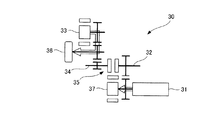
一方、パラレル走行は、図10に示すように、エンジン31を駆動して、車両30のタイヤ36を駆動しているが、クラッチ35を結合状態としており、これにより、エンジン31の駆動力をモータ軸34側(駆動軸側)へ伝達している。なお、パラレル走行は、エンジン31及びモータ33を共に駆動して、車両30のタイヤ36を駆動する場合もある。
On the other hand, as shown in FIG. 10, in parallel traveling, the
このように、ハイブリッド車の車両30は、モータ33を駆動力とするEV走行時及びシリーズ走行時には、クラッチ35を開放し、エンジン軸32とモータ軸34とを機械的に動力遮断した状態で走行している。これに対し、エンジン31を駆動力とするパラレル走行時には、クラッチ35を結合し、エンジン軸32とモータ軸34とを機械的に結合した状態で走行している。
As described above, the
従って、EV走行及びシリーズ走行からパラレル走行へモード変更するときには、開放していたクラッチ35を結合し、逆に、パラレル走行からEV走行及びシリーズ走行へモード変更するときには、結合していたクラッチ35を開放するようにしている。
Accordingly, when changing the mode from EV running and series running to parallel running, the released
パラレル走行からシリーズ走行へモード変更するときには、結合していたクラッチ35を開放することで、駆動力がエンジン31からモータ33へシフトする。このとき、クラッチ35の動作状況はクラッチ圧力センサ(図示省略)で行っているが、クラッチ圧力センサの故障時には、クラッチ35の動作状況を把握することができず、二次故障に繋がる原因となる。
When changing the mode from parallel travel to series travel, the driving force is shifted from the
本発明は上記課題に鑑みなされたもので、ハイブリット車の走行モードを変更する際、クラッチ圧力センサが故障していても、二次故障の発生を低減することができるハイブリット車のクラッチ制御装置を提供することを目的とする。 SUMMARY OF THE INVENTION The present invention has been made in view of the above problems, and provides a clutch control device for a hybrid vehicle that can reduce the occurrence of secondary failure even when the clutch pressure sensor has failed when changing the travel mode of the hybrid vehicle. The purpose is to provide.
上記課題を解決する第1の発明に係るハイブリット車のクラッチ制御装置は、
モータにより駆動され、駆動軸と接続されたモータ軸とエンジンにより駆動されるエンジン軸との間の結合/開放を行うクラッチと、
油圧により前記クラッチの結合/開放を制御する油圧手段と、
前記油圧の油温を検知する油温検知手段と、
車両の車速を検知する車速検知手段と、
前記モータ軸と前記エンジン軸との間を結合して、前記エンジンにより前記車両を駆動するエンジン走行状態と、前記モータ軸と前記エンジン軸との間を開放して、前記モータにより前記車両を駆動するモータ走行状態との切り換えを、前記油圧手段を介し、前記クラッチを制御して行う制御手段とを有し、
前記制御手段は、
前記エンジン走行状態から前記モータ走行状態へ変更する際、前記クラッチが結合している状態から完全に開放するまでの応答時間を、前記車速に対する推定時間マップから求める第1推定時間と前記油温に対する推定時間マップから求める第2推定時間とを比較して、いずれか大きい方を前記応答時間として求め、
前記クラッチの開放制御を開始してから前記応答時間経過後、前記クラッチを完全に開放したと判断して、前記モータ走行状態における制御を許可することを特徴とする。
上記課題を解決する第2の発明に係るハイブリット車のクラッチ制御装置は、
上記第1の発明に記載のハイブリット車のクラッチ制御装置において、
前記車速に対する推定時間マップは、所定車速までは車速の増加に反比例して推定時間が減少し、前記所定車速以降は推定時間が一定し、
前記油温に対する推定時間マップは、所定油温までは油温の増加に反比例して推定時間が減少し、前記所定油温以降は油温の増加に略比例して推定時間が増加することを特徴とする。
A clutch control device for a hybrid vehicle according to a first aspect of the present invention for solving the above-described problem is provided.
A clutch driven by a motor and coupled / released between a motor shaft connected to the drive shaft and an engine shaft driven by the engine;
Hydraulic means for controlling engagement / disengagement of the clutch by hydraulic pressure;
Oil temperature detecting means for detecting the oil temperature of the oil pressure;
Vehicle speed detection means for detecting the vehicle speed;
An engine running state in which the motor shaft and the engine shaft are coupled to drive the vehicle by the engine, and a space between the motor shaft and the engine shaft is opened, and the vehicle is driven by the motor. Control means for controlling the clutch by controlling the clutch through the hydraulic means,
The control means includes
When changing from the engine running state to the motor running condition, the response time from the state before Symbol clutch is attached until completely open, the oil temperature and the first estimated time for obtaining the estimated time map for the vehicle speed Is compared with the second estimated time obtained from the estimated time map for, and the larger one is obtained as the response time ,
After the response time has elapsed after starting the clutch release control, it is determined that the clutch has been completely released, and the control in the motor running state is permitted.
A clutch control device for a hybrid vehicle according to a second invention for solving the above-described problems is provided.
In the clutch control device for a hybrid vehicle according to the first invention,
In the estimated time map for the vehicle speed, the estimated time decreases in inverse proportion to the increase in vehicle speed up to a predetermined vehicle speed, and the estimated time is constant after the predetermined vehicle speed,
The estimated time map for the oil temperature indicates that the estimated time decreases in inverse proportion to the increase in oil temperature up to a predetermined oil temperature, and that the estimated time increases in proportion to the increase in oil temperature after the predetermined oil temperature. Features.
上記課題を解決する第3の発明に係るハイブリット車のクラッチ制御装置は、
上記第1又は第2の発明に記載のハイブリット車のクラッチ制御装置において、
前記モータ軸のモータ軸回転数を検知するモータ軸回転数検知手段と、前記エンジン軸のエンジン軸回転数を検知するエンジン軸回転数検知手段とを更に有し、
前記制御手段は、
前記クラッチの開放制御を開始してから前記応答時間経過後、前記モータを制御し、走行に必要なモータ軸目標回転数で前記モータ軸を回転させると共に、前記エンジンを制御し、前記モータ軸目標回転数と所定回転数異なるエンジン軸目標回転数で前記エンジン軸を回転させ、
検知した前記モータ軸回転数と検知した前記エンジン軸回転数との差が前記所定回転数以上のとき、前記クラッチが完全に開放したと判断して、前記モータ走行状態における制御を許可することを特徴とする。
A clutch control device for a hybrid vehicle according to a third aspect of the present invention for solving the above-described problem is provided.
In the clutch control device for a hybrid vehicle according to the first or second invention,
Motor shaft rotational speed detection means for detecting the motor shaft rotational speed of the motor shaft; and engine shaft rotational speed detection means for detecting the engine shaft rotational speed of the engine shaft;
The control means includes
After the response time elapses after starting the clutch release control, the motor is controlled, the motor shaft is rotated at a motor shaft target rotational speed necessary for traveling, the engine is controlled, and the motor shaft target is controlled. The engine shaft is rotated at a target engine shaft speed that is different from the predetermined speed.
When the difference between the detected motor shaft rotational speed and the detected engine shaft rotational speed is equal to or greater than the predetermined rotational speed, it is determined that the clutch is completely released, and control in the motor running state is permitted. Features.
上記課題を解決する第4の発明に係るハイブリット車のクラッチ制御装置は、
上記第3の発明に記載のハイブリット車のクラッチ制御装置において、
前記制御手段は、
検知した前記モータ軸回転数と検知した前記エンジン軸回転数との差が前記所定回転数未満のとき、前記クラッチに故障があると判定し、前記モータ走行状態における制御を禁止することを特徴とする。
A clutch control device for a hybrid vehicle according to a fourth aspect of the present invention for solving the above-described problem is provided.
In the clutch control device for a hybrid vehicle according to the third invention,
The control means includes
When the difference between the detected motor shaft rotational speed and the detected engine shaft rotational speed is less than the predetermined rotational speed, it is determined that the clutch is faulty, and control in the motor running state is prohibited. To do.
第1、第2の発明によれば、車速に対する推定時間マップから求める第1推定時間と油温に対する推定時間マップから求める第2推定時間とを比較して、いずれか大きい方を応答時間として求め、求めた応答時間経過後に、モータ走行状態における制御を許可するので、クラッチ圧力センサが故障した場合でも、二次故障の発生を低減することができる。 According to the first and second inventions, the first estimated time obtained from the estimated time map for the vehicle speed is compared with the second estimated time obtained from the estimated time map for the oil temperature, and the larger one is obtained as the response time. Since the control in the motor running state is permitted after the obtained response time has elapsed, the occurrence of secondary failure can be reduced even when the clutch pressure sensor fails.
第3、第4の発明によれば、車速と油温により応答時間を求め、求めた応答時間経過後に、差回転制御を行って、クラッチの故障判定を行い、その判定結果に基づいて、モータ走行状態における制御の許可/不許可を判断するので、クラッチ圧力センサが故障した場合でも、二次故障の発生を低減することができる。又、クラッチの故障判定を行うので、その判定結果に基づいて、クラッチの故障通知も可能となる。 According to the third and fourth inventions, the response time is obtained from the vehicle speed and the oil temperature, and after the obtained response time has elapsed, the differential rotation control is performed, the clutch failure is determined, and the motor is determined based on the determination result. Since permission / non-permission of control in the running state is determined, even when the clutch pressure sensor fails, occurrence of secondary failure can be reduced. Further, since the clutch failure determination is performed, the clutch failure notification can be performed based on the determination result.
以下、本発明に係るハイブリット車のクラッチ制御装置の実施形態について、図1〜図7を参照して説明を行う。 Embodiments of a clutch control device for a hybrid vehicle according to the present invention will be described below with reference to FIGS.
(実施例1)
図1は、本発明に係るハイブリット車のクラッチ制御装置を有する車両の構成図である。又、図2は、油圧制御弁の油圧特性を説明するグラフであり、図3は、油圧制御弁の油圧応答性を説明するグラフである。又、図4、図5は、本発明に係るハイブリット車のクラッチ制御装置における制御を説明する図であり、図4は、その制御を説明するフローチャートであり、図5は、クラッチ開放時間を演算するときのブロック図である。
Example 1
FIG. 1 is a configuration diagram of a vehicle having a clutch control device for a hybrid vehicle according to the present invention. FIG. 2 is a graph illustrating the hydraulic characteristics of the hydraulic control valve, and FIG. 3 is a graph illustrating the hydraulic response of the hydraulic control valve. 4 and 5 are diagrams for explaining control in the clutch control device for a hybrid vehicle according to the present invention. FIG. 4 is a flowchart for explaining the control. FIG. It is a block diagram when doing.
本実施例のハイブリッド車のクラッチ制御装置において、車両10は、図1に示すように、エンジン11とモータ15とを動力源とするハイブリッド車である。具体的には、車両駆動を行うと共に発電の動力源となるエンジン11と、エンジン11により駆動されて発電を行う発電機12と、発電機12により発電された電気を充電する高圧バッテリ13と、インバータ14を介して、発電機12、高圧バッテリ13から電気を供給して、発電機12で発電された電気、高圧バッテリ13に充電された電気の少なくとも一方を用いて、車両駆動を行うモータ15とを有している。
In the clutch control apparatus for a hybrid vehicle of this embodiment, the
モータ15は、前輪18の駆動軸を駆動しており、ギアボックス(変速機)17を介して(詳細には、ギアボックス17内のディファレンシャルを介して)、前輪18の駆動軸と接続されている。一方、エンジン11も、ギアボックス17を介して、前輪18と接続されるが、前輪18の駆動軸を駆動する際には、ギアボックス17の内部に設けたクラッチ16を介して(更には、ギアボックス17内のディファレンシャルを介して)、接続されている。このクラッチ16は、ソレノイド等の油圧制御弁(油圧手段;図示省略)により制御されるものであり、具体的には、エンジン11のエンジン軸(後述する図7中のエンジン軸25参照)とモータ15のモータ軸(後述する図7中のモータ軸26参照)との間の結合/開放を行っている。クラッチ16、ギアボックス17の構成は公知のいずれの構成でもよいので、ここでは、その詳細な説明は割愛する。又、クラッチ16は、ギアボックス17から独立した構成でもよく、又、湿式(単板/多板)、乾式(単板/多板)のいずれのものを用いてもよい。
The
なお、本実施例では、一例として、前輪18側にモータ15を設けた構成としているが、後輪19側を駆動するモータを更に設けた構成としてもよい。又、本実施例では、エンジン11を駆動し、発電機12により発電して、高圧バッテリ13へ充電するハイブリッド車を例示しているが、車両外部の家庭用電源や急速充電器から高圧バッテリ13への充電も可能とするプラグインハイブリッド車であってもよい。
In the present embodiment, as an example, the
そして、車両10は、エンジン11を制御するエンジンECU(Electronics Control Unit)21と、発電機12を制御するジェネレータECU22と有し、又、高圧バッテリ13、モータ15、ギアボックス17(クラッチ16)を制御するEV−ECU(車両統合制御コントローラ;制御手段)23を有している。なお、高圧バッテリ13は、高圧バッテリ13の管理を行うBMU(Battery Management Unit)24を介して、EV−ECU23と接続されており、BMU24は、高圧バッテリ13の電圧、電流、温度、SOC(State of Charge;充電率)等を監視し、EV−ECU23へは、電圧、電流、温度、SOC等を通知している。
The
エンジンECU21、ジェネレータECU22及びEV−ECU23同士は、例えば、CAN(Controller Area Network)等を用いて、互いの情報を送受信可能である。本実施例のクラッチ制御装置においては、EV−ECU23が主となって、車両10の車速及び要求される駆動力に応じて、クラッチ16を制御して、バッテリ駆動のEV走行、バッテリ駆動とエンジン発電を併用するシリーズ走行、エンジン直動のパラレル走行を切り換えており、その際、後述するクラッチ制御を行っている。
The
なお、EV−ECU23は、車速センサ(車速検知手段;図示省略)から車両10の車速を検知すると共に、アクセルペダル(図示省略)から検知したアクセル開度等に基づいて、必要とする駆動力を求めている。又、クラッチ16の油温センサ(油温検知手段;図示省略)からクラッチ16のクラッチオイルの油温を検知すると共に、独立して複数設けられた回転数センサ(モータ軸回転数検知手段、エンジン軸回転数検知手段;図示省略)から、エンジン11側のエンジン軸(図7のエンジン軸25参照)の回転数、モータ15側のモータ軸(図7のモータ軸26参照)の回転数を独立して検知している。
The EV-
最初に、図2、図3を参照して、油圧制御弁の油圧特性、油圧応答性を説明する。 First, with reference to FIG. 2 and FIG. 3, the hydraulic characteristics and hydraulic response of the hydraulic control valve will be described.
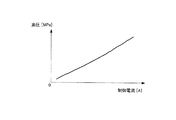
クラッチ16の結合/開放を制御する油圧制御弁(ソレノイド)は、図2のグラフに示すように、EV−ECU23からの制御電流に略比例して単調増加する油圧特性を有しており、EV−ECU23は、その油圧特性に従って、制御電流を制御して、油圧制御弁を制御している。
The hydraulic control valve (solenoid) that controls the coupling / release of the clutch 16 has a hydraulic characteristic that monotonously increases in proportion to the control current from the EV-
一方、油圧制御弁には、機械的な遅れ時間が生じるため、クラッチ16へ供給される油圧の変化にも遅れ時間が生じ、クラッチ16の応答性にも遅れ時間が生じる。例えば、クラッチ16を開放する場合、図3のグラフに示すように、EV−ECU23からの制御電流を、クラッチ結合制御電流からクラッチ開放制御電流に変更しても、クラッチ16へ供給される油圧の変化に遅れ時間が生じるため、結合していたクラッチ16が完全に開放されるまで、クラッチ開放時間Taで示す応答時間が必要である。従って、一定の応答時間を設定すれば、クラッチ圧力センサが故障した場合でも、二次故障の発生を低減できそうである。ところが、このクラッチ開放時間Taは、後述する図5で説明するように、車速、クラッチ油温に依存するため、一定の応答時間を設定しただけでは、二次故障の発生を防ぎきれない。
On the other hand, since a mechanical delay time occurs in the hydraulic control valve, a delay time also occurs in the change in the hydraulic pressure supplied to the clutch 16, and a delay time also occurs in the response of the clutch 16. For example, when the clutch 16 is released, as shown in the graph of FIG. 3, even if the control current from the EV-
そこで、本実施例においては、図4に示すフローチャート、図5に示すブロック図に基づいて、以下のクラッチ制御を行っている。以下、EV−ECU23における制御手順について、図4のフローチャートに沿って説明を行う。
Therefore, in this embodiment, the following clutch control is performed based on the flowchart shown in FIG. 4 and the block diagram shown in FIG. Hereinafter, the control procedure in the EV-
(ステップS1)
EV−ECU23において、クラッチ開放フラグがONであるかどうか確認する。クラッチ開放フラグがONであれば、クラッチ16が開放状態であり、EV走行又はシリーズ走行中であるので、一連の制御手順を終了し、クラッチ開放フラグがONでなければ、クラッチ16が結合状態であり、パラレル走行中であるので、ステップS2へ進む。
(Step S1)
In the EV-
(ステップS2)
パラレル走行が終了かどうか確認する。例えば、車両10の車速が、パラレル走行からEV走行、シリーズ走行へモード変更する速度となれば、パラレル走行が終了となる。パラレル走行が終了する場合には、ステップS3へ進み、パラレル走行が終了しない場合には、一連の制御手順を終了する。
(Step S2)
Check if parallel driving is finished. For example, when the vehicle speed of the
(ステップS3)
EV−ECU23から油圧制御弁にクラッチ開放制御電流を流し、ステップS4へ進む。
(Step S3)
A clutch release control current is supplied from the EV-
(ステップS4)
クラッチ開放時間Ta(応答時間)を推定時間マップにより演算する。
(Step S4)
The clutch release time Ta (response time) is calculated from the estimated time map.
ここで、クラッチ開放時間Taの演算について、図5を参照して説明する。クラッチ開放時間Taについては、図5に示すように、第1演算部B1において、車速に対する推定時間のマップから、車速d1に対する第1推定時間T1を求め、第2演算部B2において、油温に対する推定時間のマップから、クラッチ16の油温d2に対する第2推定時間T2を求め、第3演算部B3において、第1推定時間T1、第2推定時間T2のうち、いずれか大きい方をクラッチ開放時間Taとしている。 Here, the calculation of the clutch release time Ta will be described with reference to FIG. For the clutch release time Ta, as shown in FIG. 5, the first calculation unit B1 obtains the first estimated time T1 for the vehicle speed d1 from the map of the estimated time for the vehicle speed, and the second calculation unit B2 From the estimated time map, the second estimated time T2 with respect to the oil temperature d2 of the clutch 16 is obtained, and in the third computing unit B3, the larger one of the first estimated time T1 and the second estimated time T2 is determined as the clutch disengaged time. Ta.
なお、車速に対する推定時間は、第1演算部B1のマップに示すように、ある車速までは車速の増加に反比例して減少していき、ある車速以降は一定となる傾向である。一方、油温に対する推定時間は、第2演算部B2のマップに示すように、ある油温までは油温の増加に略反比例して減少していき、ある油温以降は油温の増加に略比例して増加していく傾向である。 The estimated time for the vehicle speed tends to decrease in inverse proportion to the increase in vehicle speed up to a certain vehicle speed and becomes constant after a certain vehicle speed, as shown in the map of the first calculation unit B1. On the other hand, as shown in the map of the second calculation unit B2, the estimated time with respect to the oil temperature decreases approximately in inverse proportion to the increase in the oil temperature until a certain oil temperature, and increases after the certain oil temperature. It tends to increase almost proportionally.
このように、クラッチ開放時間Taは、車両10の車速とクラッチ16の油温により求められ、クラッチ開放時間Taの演算後、ステップS5へ進む。
Thus, the clutch release time Ta is obtained from the vehicle speed of the
(ステップS5)
クラッチ開放制御電流を流し始めてからの経過時間Tが、演算したクラッチ開放時間Taを過ぎるまで待ち、経過時間Tがクラッチ開放時間Taを過ぎた後、ステップS6へ進む。
(Step S5)
The process waits until the elapsed time T from the start of the clutch release control current exceeds the calculated clutch release time Ta, and after the elapsed time T has passed the clutch release time Ta, the process proceeds to step S6.
(ステップS6)
EV−ECU23において、クラッチ開放フラグをONとする。その結果、後続する制御、即ち、EV走行、シリーズ走行における制御が許可されて、実施されることになる。
(Step S6)
In the EV-
このように、本実施例では、車両10の車速とクラッチ16の油温によりクラッチ開放時間Taを求め、求めたクラッチ開放時間Taの経過後に、つまり、結合していたクラッチ16が完全に開放される時間の経過後に、後続する制御を許可するので、クラッチ圧力センサが故障した場合でも、二次故障の発生を低減することができる。
As described above, in this embodiment, the clutch release time Ta is obtained from the vehicle speed of the
(実施例2)
図6、図7は、本発明に係るハイブリット車のクラッチ制御装置における他の制御を説明する図であり、図6は、その制御を説明するフローチャートであり、図7は、差回転制御を説明する図である。
(Example 2)
6 and 7 are diagrams for explaining another control in the clutch control apparatus for a hybrid vehicle according to the present invention, FIG. 6 is a flowchart for explaining the control, and FIG. 7 for explaining the differential rotation control. It is a figure to do.
本実施例においては、図6に示すフローチャート、図7に示す図に基づいて、以下のクラッチ制御を行っている。但し、本実施例のハイブリット車のクラッチ制御装置は、実施例1の図1に示したハイブリット車のクラッチ制御装置と同等の構成でよい。又、図6のフローチャートは、ステップS5とステップS6の間に挿入したステップSP1〜SP3の制御手順を除き、実施例1の図4のフローチャートと同等である。従って、ここでは、重複する説明を省略又は簡略して説明を行う。 In the present embodiment, the following clutch control is performed based on the flowchart shown in FIG. 6 and the diagram shown in FIG. However, the hybrid vehicle clutch control device of the present embodiment may have the same configuration as the hybrid vehicle clutch control device shown in FIG. The flowchart of FIG. 6 is the same as the flowchart of FIG. 4 of the first embodiment except for the control procedure of steps SP1 to SP3 inserted between steps S5 and S6. Therefore, here, a duplicate description is omitted or simplified.
以下、EV−ECU23における制御手順について、図6のフローチャートに沿って説明を行う。
Hereinafter, the control procedure in the EV-
(ステップS1)
EV−ECU23において、クラッチ開放フラグがONであるかどうか確認する。クラッチ開放フラグがONであれば、一連の制御手順を終了し、クラッチ開放フラグがONでなければ、ステップS2へ進む。
(Step S1)
In the EV-
(ステップS2)
パラレル走行が終了かどうか確認する。パラレル走行が終了する場合には、ステップS3へ進み、パラレル走行が終了でない場合には、一連の制御手順を終了する。
(Step S2)
Check if parallel driving is finished. When the parallel running is finished, the process proceeds to step S3, and when the parallel running is not finished, a series of control procedures is finished.
(ステップS3)
EV−ECU23から油圧制御弁にクラッチ開放制御電流を流し、ステップS4へ進む。
(Step S3)
A clutch release control current is supplied from the EV-
(ステップS4)
クラッチ開放時間Taを推定時間マップにより演算し、演算後、ステップS5へ進む。
(Step S4)
The clutch release time Ta is calculated from the estimated time map. After the calculation, the process proceeds to step S5.
(ステップS5)
経過時間Tがクラッチ開放時間Taを過ぎてから、ステップSP1へ進む。クラッチ開放時間Taは、次のステップSP1での差回転制御の開始タイミングを図る意味もある。
(Step S5)
After the elapsed time T has passed the clutch release time Ta, the process proceeds to step SP1. The clutch release time Ta also means the start timing of the differential rotation control in the next step SP1.
(ステップSP1)
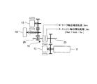
経過時間Tがクラッチ開放時間Taを過ぎた後、モータ軸とエンジン軸とが機械的に動力遮断されたかどうかを確認するため、差回転制御を行う。図7を参照して、差回転制御を説明すると、差回転制御では、モータ15を制御して、走行に必要なモータ軸目標回転数Nmt[rpm]でモータ軸26を回転させると共に、エンジン11を制御して、モータ軸目標回転数Nmtとは所定回転数(例えば、100rpm)異なるエンジン軸目標回転数Net[rpm]でエンジン軸25を回転させる。このエンジン軸目標回転数Netは、モータ軸目標回転数Nmtと異なるように、モータ軸目標回転数Nmtから差回転数Na[rpm]を減算した回転数としている。差回転制御で設定するエンジン軸目標回転数Netとしては、クラッチ16が故障している場合を考慮し、車両10の急加速を防止するために、減速側に設定することが望ましい。そのため、[(エンジン軸目標回転数Net)=(モータ軸目標回転数Nmt)−(差回転数Na)]としている。
(Step SP1)
After the elapsed time T has passed the clutch release time Ta, differential rotation control is performed in order to confirm whether the motor shaft and the engine shaft are mechanically shut off. The differential rotation control will be described with reference to FIG. 7. In the differential rotation control, the
(ステップSP2)
そして、上述した差回転制御中に、エンジン軸25及びモータ軸26の回転数を回転数センサで独立して検知すると共に、検知したエンジン軸回転数Ne、モータ軸回転数Nmが下記式1を見たすかどうか確認する。この式1を満たす場合には、ステップS6へ進み、この式1を満たさない場合には、ステップSP3へ進む。
(Step SP2)
During the above-described differential rotation control, the rotational speeds of the
|(モータ軸回転数Nm)−(エンジン軸回転数Ne)|≧(差回転数Na) … 式1
| (Motor shaft speed Nm) − (Engine shaft speed Ne) | ≧ (Differential speed Na)
(ステップS6)
クラッチ16に故障等が無く、クラッチ16が完全に開放されていたら、モータ軸回転数Nm=モータ軸目標回転数Nmtであり、エンジン軸回転数Ne=エンジン軸目標回転数Netであり、上記式1を満たすことになる。従って、式1を満たす場合には、クラッチ16が開放状態であることを確認することになり、EV−ECU23において、クラッチ開放フラグをONとする。その結果、後続する制御、即ち、EV走行、シリーズ走行における制御が許可されて、実施されることになる。
(Step S6)
If the clutch 16 is not broken and the clutch 16 is completely opened, the motor shaft rotational speed Nm = the motor shaft target rotational speed Nmt, the engine shaft rotational speed Ne = the engine shaft target rotational speed Net, and the
(ステップSP3)
一方、故障(例えば、固着)等によりクラッチ16が結合したままの状態であれば、モータ軸回転数Nmはモータ軸目標回転数Nmtと一致せず、エンジン軸回転数Neもエンジン軸目標回転数Netと一致せず、互いに同期するような回転数となり、上記式1を満たせない。従って、式1を満たさない場合には、クラッチが結合(又は半クラッチ)であると故障判定することができ、EV−ECU23において、クラッチ開放フラグをONとすることはない。その結果、後続する制御、即ち、EV走行、シリーズ走行における制御を禁止して、二次故障の発生を低減することができる。
(Step SP3)
On the other hand, if the clutch 16 remains engaged due to a failure (for example, sticking) or the like, the motor shaft rotational speed Nm does not match the motor shaft target rotational speed Nmt, and the engine shaft rotational speed Ne is also the engine shaft target rotational speed. The number of rotations does not coincide with Net and is synchronized with each other, and the
このように、本実施例では、車両10の車速とクラッチ16の油温によりクラッチ開放時間Taを求め、求めたクラッチ開放時間Taの経過後に、差回転制御を行って、クラッチ16の故障判定を行い、その判定結果に基づいて、後続する制御の許可/不許可を判断するので、クラッチ圧力センサが故障した場合でも、二次故障の発生を低減することができる。又、クラッチ16の故障判定を行うので、その判定結果に基づいて、クラッチ16の故障通知も可能となる。
Thus, in this embodiment, the clutch release time Ta is obtained from the vehicle speed of the
本発明は、ハイブリッド車に好適なものである。 The present invention is suitable for a hybrid vehicle.
10 車両
11 エンジン
12 発電機
13 高圧バッテリ
15 モータ
16 クラッチ
23 EV−ECU
24 BMU
DESCRIPTION OF
24 BMU
Claims (4)
油圧により前記クラッチの結合/開放を制御する油圧手段と、
前記油圧の油温を検知する油温検知手段と、
車両の車速を検知する車速検知手段と、
前記モータ軸と前記エンジン軸との間を結合して、前記エンジンにより前記車両を駆動するエンジン走行状態と、前記モータ軸と前記エンジン軸との間を開放して、前記モータにより前記車両を駆動するモータ走行状態との切り換えを、前記油圧手段を介し、前記クラッチを制御して行う制御手段とを有し、
前記制御手段は、
前記エンジン走行状態から前記モータ走行状態へ変更する際、前記クラッチが結合している状態から完全に開放するまでの応答時間を、前記車速に対する推定時間マップから求める第1推定時間と前記油温に対する推定時間マップから求める第2推定時間とを比較して、いずれか大きい方を前記応答時間として求め、
前記クラッチの開放制御を開始してから前記応答時間経過後、前記クラッチを完全に開放したと判断して、前記モータ走行状態における制御を許可することを特徴とするハイブリット車のクラッチ制御装置。 A clutch driven by a motor and coupled / released between a motor shaft connected to the drive shaft and an engine shaft driven by the engine;
Hydraulic means for controlling engagement / disengagement of the clutch by hydraulic pressure;
Oil temperature detecting means for detecting the oil temperature of the oil pressure;
Vehicle speed detection means for detecting the vehicle speed;
An engine running state in which the motor shaft and the engine shaft are coupled to drive the vehicle by the engine, and a space between the motor shaft and the engine shaft is opened, and the vehicle is driven by the motor. Control means for controlling the clutch by controlling the clutch through the hydraulic means,
The control means includes
When changing from the engine running state to the motor running condition, the response time from the state before Symbol clutch is attached until completely open, the oil temperature and the first estimated time for obtaining the estimated time map for the vehicle speed Is compared with the second estimated time obtained from the estimated time map for, and the larger one is obtained as the response time ,
The hybrid vehicle clutch control device, wherein after the response time has elapsed after starting the clutch release control, it is determined that the clutch has been completely released, and the control in the motor running state is permitted.
前記車速に対する推定時間マップは、所定車速までは車速の増加に反比例して推定時間が減少し、前記所定車速以降は推定時間が一定し、In the estimated time map for the vehicle speed, the estimated time decreases in inverse proportion to the increase in vehicle speed up to a predetermined vehicle speed, and the estimated time is constant after the predetermined vehicle speed,
前記油温に対する推定時間マップは、所定油温までは油温の増加に反比例して推定時間が減少し、前記所定油温以降は油温の増加に略比例して推定時間が増加することを特徴とするハイブリット車のクラッチ制御装置。The estimated time map for the oil temperature indicates that the estimated time decreases in inverse proportion to the increase in oil temperature up to a predetermined oil temperature, and that the estimated time increases in proportion to the increase in oil temperature after the predetermined oil temperature. A clutch control device for a hybrid vehicle.
前記モータ軸のモータ軸回転数を検知するモータ軸回転数検知手段と、前記エンジン軸のエンジン軸回転数を検知するエンジン軸回転数検知手段とを更に有し、
前記制御手段は、
前記クラッチの開放制御を開始してから前記応答時間経過後、前記モータを制御し、走行に必要なモータ軸目標回転数で前記モータ軸を回転させると共に、前記エンジンを制御し、前記モータ軸目標回転数と所定回転数異なるエンジン軸目標回転数で前記エンジン軸を回転させ、
検知した前記モータ軸回転数と検知した前記エンジン軸回転数との差が前記所定回転数以上のとき、前記クラッチが完全に開放したと判断して、前記モータ走行状態における制御を許可することを特徴とするハイブリット車のクラッチ制御装置。 In the clutch control device for a hybrid vehicle according to claim 1 or 2 ,
Motor shaft rotational speed detection means for detecting the motor shaft rotational speed of the motor shaft; and engine shaft rotational speed detection means for detecting the engine shaft rotational speed of the engine shaft;
The control means includes
After the response time elapses after starting the clutch release control, the motor is controlled, the motor shaft is rotated at a motor shaft target rotational speed necessary for traveling, the engine is controlled, and the motor shaft target is controlled. The engine shaft is rotated at a target engine shaft speed that is different from the predetermined speed.
When the difference between the detected motor shaft rotational speed and the detected engine shaft rotational speed is equal to or greater than the predetermined rotational speed, it is determined that the clutch is completely released, and control in the motor running state is permitted. A clutch control device for a hybrid vehicle.
前記制御手段は、
検知した前記モータ軸回転数と検知した前記エンジン軸回転数との差が前記所定回転数未満のとき、前記クラッチに故障があると判定し、前記モータ走行状態における制御を禁止することを特徴とするハイブリット車のクラッチ制御装置。 In the hybrid vehicle clutch control device according to claim 3 ,
The control means includes
When the difference between the detected motor shaft rotational speed and the detected engine shaft rotational speed is less than the predetermined rotational speed, it is determined that the clutch is faulty, and control in the motor running state is prohibited. A clutch control device for a hybrid vehicle.
Priority Applications (4)
| Application Number | Priority Date | Filing Date | Title |
|---|---|---|---|
| JP2010228057A JP5201191B2 (en) | 2010-10-08 | 2010-10-08 | Hybrid vehicle clutch control device |
| EP11184375.1A EP2439118B1 (en) | 2010-10-08 | 2011-10-07 | Hybrid vehicle and method of controlling a hybrid vehicle |
| US13/269,181 US8538618B2 (en) | 2010-10-08 | 2011-10-07 | Clutch control device of hybrid vehicle |
| CN201110296862.XA CN102442305B (en) | 2010-10-08 | 2011-10-08 | Clutch control device of hybrid vehicle |
Applications Claiming Priority (1)
| Application Number | Priority Date | Filing Date | Title |
|---|---|---|---|
| JP2010228057A JP5201191B2 (en) | 2010-10-08 | 2010-10-08 | Hybrid vehicle clutch control device |
Publications (2)
| Publication Number | Publication Date |
|---|---|
| JP2012081811A JP2012081811A (en) | 2012-04-26 |
| JP5201191B2 true JP5201191B2 (en) | 2013-06-05 |
Family
ID=45044313
Family Applications (1)
| Application Number | Title | Priority Date | Filing Date |
|---|---|---|---|
| JP2010228057A Expired - Fee Related JP5201191B2 (en) | 2010-10-08 | 2010-10-08 | Hybrid vehicle clutch control device |
Country Status (4)
| Country | Link |
|---|---|
| US (1) | US8538618B2 (en) |
| EP (1) | EP2439118B1 (en) |
| JP (1) | JP5201191B2 (en) |
| CN (1) | CN102442305B (en) |
Families Citing this family (14)
| Publication number | Priority date | Publication date | Assignee | Title |
|---|---|---|---|---|
| WO2012053596A1 (en) * | 2010-10-22 | 2012-04-26 | 日野自動車株式会社 | Vehicle, control method, and program |
| JP5892315B2 (en) * | 2011-12-13 | 2016-03-23 | 三菱自動車工業株式会社 | Clutch control device for hybrid vehicle |
| JP2014105851A (en) * | 2012-11-30 | 2014-06-09 | Toyota Motor Corp | Travelling control device of vehicle |
| KR101405198B1 (en) * | 2012-12-07 | 2014-06-27 | 기아자동차 주식회사 | Method and system for controlling anti jerk of hybrid electric vehicle |
| JP5618105B2 (en) * | 2013-01-09 | 2014-11-05 | 三菱自動車工業株式会社 | Control device for hybrid vehicle |
| US9415772B2 (en) | 2013-03-14 | 2016-08-16 | Textron Innovations Inc. | Rear drive module for a vehicle |
| JP6070831B2 (en) * | 2013-04-26 | 2017-02-01 | 日産自動車株式会社 | Clutch control device for hybrid vehicle |
| JP6079521B2 (en) * | 2013-09-13 | 2017-02-15 | 日産自動車株式会社 | Hybrid vehicle |
| CN103465899B (en) * | 2013-09-23 | 2016-06-29 | 湖南南车时代电动汽车股份有限公司 | A kind of series-parallel connection car engine starts and controls system and method |
| CN105593045B (en) * | 2013-09-30 | 2017-11-21 | 日产自动车株式会社 | The control device and control method of motor vehicle driven by mixed power |
| JP6156243B2 (en) * | 2014-04-16 | 2017-07-05 | トヨタ自動車株式会社 | Control device for hybrid vehicle |
| JP6481193B2 (en) * | 2014-06-13 | 2019-03-13 | 三菱自動車工業株式会社 | Electric vehicle |
| CN110861596B (en) * | 2018-08-27 | 2021-04-06 | 广州汽车集团股份有限公司 | Method, device, control device and storage medium for regulating main oil pressure |
| CN111156265B (en) * | 2019-12-25 | 2021-09-28 | 中国第一汽车股份有限公司 | Method and device for determining clutch pressure, vehicle and storage medium |
Family Cites Families (19)
| Publication number | Priority date | Publication date | Assignee | Title |
|---|---|---|---|---|
| JP3322072B2 (en) * | 1994-08-12 | 2002-09-09 | トヨタ自動車株式会社 | Power transmission lubrication system |
| JP3172490B2 (en) * | 1998-05-18 | 2001-06-04 | 株式会社日立製作所 | Hybrid car |
| JP3424562B2 (en) * | 1998-09-16 | 2003-07-07 | 日産自動車株式会社 | Transmission control device for automatic transmission |
| JP4218129B2 (en) * | 1999-05-24 | 2009-02-04 | アイシン・エィ・ダブリュ株式会社 | Hydraulic pressure generator and hybrid vehicle using the same |
| US7103463B2 (en) * | 2004-05-15 | 2006-09-05 | General Motors Corporation | Hydraulic clutch state diagnostic and control |
| JP3702897B2 (en) | 2004-05-24 | 2005-10-05 | 日産自動車株式会社 | Control device for hybrid vehicle |
| US7322903B2 (en) * | 2006-02-27 | 2008-01-29 | Ford Global Technologies, Llc | Control method for cooling a launch clutch and an electric motor in a hybrid electric vehicle powertrain |
| JP4396661B2 (en) * | 2006-05-26 | 2010-01-13 | 日産自動車株式会社 | Clutch engagement control device for hybrid vehicle |
| JP2008081099A (en) | 2006-08-29 | 2008-04-10 | Nissan Motor Co Ltd | Controller for hybrid car |
| JP4867594B2 (en) * | 2006-11-10 | 2012-02-01 | 日産自動車株式会社 | Vehicle control device |
| JP2008185081A (en) * | 2007-01-29 | 2008-08-14 | Toyota Motor Corp | Clutch engaged state determination apparatus, gear determination apparatus, and shift indication apparatus |
| JP2008303918A (en) * | 2007-06-05 | 2008-12-18 | Toyota Motor Corp | Operating oil cooling device for automatic transmission |
| KR100992771B1 (en) * | 2007-09-05 | 2010-11-05 | 기아자동차주식회사 | Method for controlling idle stop mode of HEV |
| JP2008002687A (en) * | 2007-09-25 | 2008-01-10 | Fujitsu Ten Ltd | Control device for continuously variable transmission |
| US8079933B2 (en) * | 2007-11-04 | 2011-12-20 | GM Global Technology Operations LLC | Method and apparatus to control engine torque to peak main pressure for a hybrid powertrain system |
| KR100992781B1 (en) * | 2007-12-13 | 2010-11-05 | 기아자동차주식회사 | System For Control Of Clutch Binding Of Hybrid Vehicle And Method Thereof |
| JP2009274566A (en) | 2008-05-14 | 2009-11-26 | Honda Motor Co Ltd | Vehicle control device |
| JP5187111B2 (en) * | 2008-10-06 | 2013-04-24 | トヨタ自動車株式会社 | Vehicle drive control device |
| JP2010188776A (en) * | 2009-02-16 | 2010-09-02 | Nissan Motor Co Ltd | Controller for hybrid vehicle |
-
2010
- 2010-10-08 JP JP2010228057A patent/JP5201191B2/en not_active Expired - Fee Related
-
2011
- 2011-10-07 EP EP11184375.1A patent/EP2439118B1/en not_active Not-in-force
- 2011-10-07 US US13/269,181 patent/US8538618B2/en active Active
- 2011-10-08 CN CN201110296862.XA patent/CN102442305B/en not_active Expired - Fee Related
Also Published As
| Publication number | Publication date |
|---|---|
| CN102442305B (en) | 2014-10-15 |
| CN102442305A (en) | 2012-05-09 |
| US8538618B2 (en) | 2013-09-17 |
| US20120089285A1 (en) | 2012-04-12 |
| EP2439118B1 (en) | 2013-05-29 |
| JP2012081811A (en) | 2012-04-26 |
| EP2439118A1 (en) | 2012-04-11 |
Similar Documents
| Publication | Publication Date | Title |
|---|---|---|
| JP5201191B2 (en) | Hybrid vehicle clutch control device | |
| JP6048585B2 (en) | Start-up control device and start-up control method for hybrid vehicle | |
| JP5201190B2 (en) | Hybrid vehicle clutch control device | |
| US9005077B2 (en) | Method to reduce lash clunk in a hybrid electric vehicle | |
| JP6156243B2 (en) | Control device for hybrid vehicle | |
| WO2011125775A1 (en) | Control device | |
| WO2012043555A1 (en) | Control device | |
| JP5125727B2 (en) | Hybrid vehicle start control device | |
| US9199637B1 (en) | Engine autostop control system and method for hybrid powertrain | |
| JP2014196101A5 (en) | ||
| JPWO2013062124A1 (en) | Control device for hybrid vehicle | |
| US9096208B2 (en) | Controlling a traction motor during engine pull-up in a vehicle | |
| EP3030464B1 (en) | Control system for hybrid vehicle | |
| WO2015049806A1 (en) | Hybrid vehicle control device | |
| JP2015020590A (en) | Hybrid vehicle control device | |
| JP5212199B2 (en) | Clutch control device for hybrid vehicle | |
| JP2015081074A (en) | Controller for vehicle | |
| JP5476721B2 (en) | Control device for hybrid vehicle | |
| JP2017047733A (en) | Start control method and start control apparatus for hybrid vehicle | |
| JP6260173B2 (en) | Vehicle control device | |
| JP2009262659A (en) | Starting controller for hybrid vehicle | |
| JP6492908B2 (en) | Control device for hybrid vehicle | |
| JP6194735B2 (en) | Control device for hybrid vehicle | |
| JP2014213748A (en) | Vehicle control device | |
| JP5598256B2 (en) | Control device for hybrid vehicle |
Legal Events
| Date | Code | Title | Description |
|---|---|---|---|
| A621 | Written request for application examination |
Free format text: JAPANESE INTERMEDIATE CODE: A621 Effective date: 20120927 |
|
| A131 | Notification of reasons for refusal |
Free format text: JAPANESE INTERMEDIATE CODE: A131 Effective date: 20121023 |
|
| A521 | Request for written amendment filed |
Free format text: JAPANESE INTERMEDIATE CODE: A523 Effective date: 20121220 |
|
| TRDD | Decision of grant or rejection written | ||
| A01 | Written decision to grant a patent or to grant a registration (utility model) |
Free format text: JAPANESE INTERMEDIATE CODE: A01 Effective date: 20130115 |
|
| A61 | First payment of annual fees (during grant procedure) |
Free format text: JAPANESE INTERMEDIATE CODE: A61 Effective date: 20130128 |
|
| R151 | Written notification of patent or utility model registration |
Ref document number: 5201191 Country of ref document: JP Free format text: JAPANESE INTERMEDIATE CODE: R151 |
|
| FPAY | Renewal fee payment (event date is renewal date of database) |
Free format text: PAYMENT UNTIL: 20160222 Year of fee payment: 3 |
|
| S531 | Written request for registration of change of domicile |
Free format text: JAPANESE INTERMEDIATE CODE: R313531 |
|
| R350 | Written notification of registration of transfer |
Free format text: JAPANESE INTERMEDIATE CODE: R350 |
|
| LAPS | Cancellation because of no payment of annual fees |