US8535864B2 - Magenta toner, developer, toner cartridge, process cartridge, image forming apparatus, and image forming method - Google Patents
Magenta toner, developer, toner cartridge, process cartridge, image forming apparatus, and image forming method Download PDFInfo
- Publication number
- US8535864B2 US8535864B2 US13/352,786 US201213352786A US8535864B2 US 8535864 B2 US8535864 B2 US 8535864B2 US 201213352786 A US201213352786 A US 201213352786A US 8535864 B2 US8535864 B2 US 8535864B2
- Authority
- US
- United States
- Prior art keywords
- toner
- image
- developer
- magenta toner
- range
- Prior art date
- Legal status (The legal status is an assumption and is not a legal conclusion. Google has not performed a legal analysis and makes no representation as to the accuracy of the status listed.)
- Expired - Fee Related, expires
Links
Images


Classifications
-
- G—PHYSICS
- G03—PHOTOGRAPHY; CINEMATOGRAPHY; ANALOGOUS TECHNIQUES USING WAVES OTHER THAN OPTICAL WAVES; ELECTROGRAPHY; HOLOGRAPHY
- G03G—ELECTROGRAPHY; ELECTROPHOTOGRAPHY; MAGNETOGRAPHY
- G03G9/00—Developers
- G03G9/08—Developers with toner particles
- G03G9/09—Colouring agents for toner particles
- G03G9/0906—Organic dyes
-
- G—PHYSICS
- G03—PHOTOGRAPHY; CINEMATOGRAPHY; ANALOGOUS TECHNIQUES USING WAVES OTHER THAN OPTICAL WAVES; ELECTROGRAPHY; HOLOGRAPHY
- G03G—ELECTROGRAPHY; ELECTROPHOTOGRAPHY; MAGNETOGRAPHY
- G03G9/00—Developers
- G03G9/08—Developers with toner particles
- G03G9/0802—Preparation methods
- G03G9/081—Preparation methods by mixing the toner components in a liquefied state; melt kneading; reactive mixing
-
- G—PHYSICS
- G03—PHOTOGRAPHY; CINEMATOGRAPHY; ANALOGOUS TECHNIQUES USING WAVES OTHER THAN OPTICAL WAVES; ELECTROGRAPHY; HOLOGRAPHY
- G03G—ELECTROGRAPHY; ELECTROPHOTOGRAPHY; MAGNETOGRAPHY
- G03G9/00—Developers
- G03G9/08—Developers with toner particles
- G03G9/0819—Developers with toner particles characterised by the dimensions of the particles
-
- G—PHYSICS
- G03—PHOTOGRAPHY; CINEMATOGRAPHY; ANALOGOUS TECHNIQUES USING WAVES OTHER THAN OPTICAL WAVES; ELECTROGRAPHY; HOLOGRAPHY
- G03G—ELECTROGRAPHY; ELECTROPHOTOGRAPHY; MAGNETOGRAPHY
- G03G9/00—Developers
- G03G9/08—Developers with toner particles
- G03G9/0827—Developers with toner particles characterised by their shape, e.g. degree of sphericity
-
- G—PHYSICS
- G03—PHOTOGRAPHY; CINEMATOGRAPHY; ANALOGOUS TECHNIQUES USING WAVES OTHER THAN OPTICAL WAVES; ELECTROGRAPHY; HOLOGRAPHY
- G03G—ELECTROGRAPHY; ELECTROPHOTOGRAPHY; MAGNETOGRAPHY
- G03G9/00—Developers
- G03G9/08—Developers with toner particles
- G03G9/087—Binders for toner particles
- G03G9/08742—Binders for toner particles comprising macromolecular compounds obtained otherwise than by reactions only involving carbon-to-carbon unsaturated bonds
- G03G9/08755—Polyesters
-
- G—PHYSICS
- G03—PHOTOGRAPHY; CINEMATOGRAPHY; ANALOGOUS TECHNIQUES USING WAVES OTHER THAN OPTICAL WAVES; ELECTROGRAPHY; HOLOGRAPHY
- G03G—ELECTROGRAPHY; ELECTROPHOTOGRAPHY; MAGNETOGRAPHY
- G03G9/00—Developers
- G03G9/08—Developers with toner particles
- G03G9/087—Binders for toner particles
- G03G9/08775—Natural macromolecular compounds or derivatives thereof
- G03G9/08782—Waxes
-
- G—PHYSICS
- G03—PHOTOGRAPHY; CINEMATOGRAPHY; ANALOGOUS TECHNIQUES USING WAVES OTHER THAN OPTICAL WAVES; ELECTROGRAPHY; HOLOGRAPHY
- G03G—ELECTROGRAPHY; ELECTROPHOTOGRAPHY; MAGNETOGRAPHY
- G03G9/00—Developers
- G03G9/08—Developers with toner particles
- G03G9/087—Binders for toner particles
- G03G9/08784—Macromolecular material not specially provided for in a single one of groups G03G9/08702 - G03G9/08775
- G03G9/08795—Macromolecular material not specially provided for in a single one of groups G03G9/08702 - G03G9/08775 characterised by their chemical properties, e.g. acidity, molecular weight, sensitivity to reactants
-
- G—PHYSICS
- G03—PHOTOGRAPHY; CINEMATOGRAPHY; ANALOGOUS TECHNIQUES USING WAVES OTHER THAN OPTICAL WAVES; ELECTROGRAPHY; HOLOGRAPHY
- G03G—ELECTROGRAPHY; ELECTROPHOTOGRAPHY; MAGNETOGRAPHY
- G03G9/00—Developers
- G03G9/08—Developers with toner particles
- G03G9/087—Binders for toner particles
- G03G9/08784—Macromolecular material not specially provided for in a single one of groups G03G9/08702 - G03G9/08775
- G03G9/08797—Macromolecular material not specially provided for in a single one of groups G03G9/08702 - G03G9/08775 characterised by their physical properties, e.g. viscosity, solubility, melting temperature, softening temperature, glass transition temperature
-
- G—PHYSICS
- G03—PHOTOGRAPHY; CINEMATOGRAPHY; ANALOGOUS TECHNIQUES USING WAVES OTHER THAN OPTICAL WAVES; ELECTROGRAPHY; HOLOGRAPHY
- G03G—ELECTROGRAPHY; ELECTROPHOTOGRAPHY; MAGNETOGRAPHY
- G03G9/00—Developers
- G03G9/08—Developers with toner particles
- G03G9/09—Colouring agents for toner particles
- G03G9/0906—Organic dyes
- G03G9/092—Quinacridones
Definitions
- the present invention relates to a magenta toner, a developer, a toner cartridge, a process cartridge, an image forming apparatus, and an image forming method.
- an image is formed by charging the entire surface of a photosensitive member (a latent image holding member), forming an electrostatic latent image on the surface of the photosensitive member with a laser beam corresponding to image information through the exposure, developing the electrostatic latent image with a developer containing a toner to form a toner image, and then transferring and fixing the toner image to the surface of a recording medium.
- a photosensitive member a latent image holding member
- Toner used in the electrophotographic method is typically produced by molten kneading method.
- the molten kneading method includes melting and kneading a plastic resin with a pigment, a charge-controlling agent, a release agent, and a magnetic material, then cooling the kneaded materials, and pulverizing and classifying the kneaded materials.
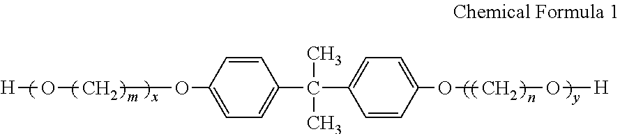
- a magenta toner including toner particles containing a colorant and a binder resin, wherein the colorant contains C.I. Pigment Red 122 and C.I. Pigment Yellow 180, and a mass ratio of the C.I. Pigment Red 122 and the C.I. Pigment Yellow 180 is in the range of 99:1 to 10000:1, the binder resin contains a polyester resin, and a polyester resin having a repeating unit obtained from a Bisphenol A alkylene oxide adduct expressed by the following chemical formula 1 is used as the polyester resin.
- n and n independently represent an integer of from 2 to 4, and x and y independently represent a positive number.
- FIG. 1 is a diagram illustrating a screw condition in an example of a screw extruder used to produce a magenta toner according to an exemplary embodiment of the invention
- FIG. 2 is a diagram schematically illustrating the configuration of an image forming apparatus according to the exemplary embodiment of the invention.
- FIG. 3 is a diagram schematically illustrating the configuration of a process cartridge according to the exemplary embodiment of the invention.
- magenta toner a magenta toner, a developer, a toner cartridge, a process cartridge, an image forming apparatus, and an image forming method according to an exemplary embodiment of the invention will be described in detail.
- a magenta toner according to an exemplary embodiment of the invention includes toner particles including a colorant and a binder resin
- the colorant includes C.I. Pigment Red 122 and C.I. Pigment Yellow 180
- a mass ratio of the C.I. Pigment Red 122 and the C.I. Pigment Yellow 180 is in the range of 99:1 to 10000:1
- the binder resin includes a polyester resin, and a polyester resin including a repeating unit obtained from a Bisphenol A alkylene oxide adduct expressed by the following chemical formula 1 is used as the polyester resin.
- n and n independently represent an integer of 2 to 4, and x and y independently represent a positive number.
- the C.I. Pigment Red 122 is a pigment having high color reproducibility, but when the C.I. Pigment Red 122 is singly used as a colorant, the reproducibility of a red image may be low in repeated copying operations in high humidity.
- the reason is thought that by aggregating the C.I. Pigment Red 122 as a colorant in the toner, permeation of the toner into a recording medium is not stabilized when a toner image is fixed to the recording medium such as a sheet of paper, and moisture in the toner becomes bubbles during fixing in high humidity to cause unevenness on the surface of the fixed image and to lower the gloss of the toner image, and thus the reproducibility of a red image in high humidity is deteriorated.
- the C.I. Pigment Red 122 often includes abietate having high viscosity for the purpose of dispersion, it is thought that the abietate on the surface of the pigment is melted to attach the pigment particles to each other and thus to aggregate the pigment particles during kneading the toner material in producing the toner, whereby the dispersibility of the pigment in the toner is lowered. Since the C.I. Pigment Red 122 can easily conjugate to molecules and easily form stable associates, it is thought that the particles of the C.I. Pigment Red 122 can easily aggregate. As a result, in the toner using the C.I. Pigment Red 122 exhibiting the above-mentioned properties as a colorant, it is thought that the initial image quality of repeated copying and the image quality after repeating 100 copies differ from each other.
- the inventors find that by adding a small amount of C.I. Pigment Yellow 180 to the C.I. Pigment Red 122 and using a polyester resin having the repeating unit obtained from Bisphenol A alkylene oxide, it is possible to improve the dispersibility of the C.I. Pigment Red 122 and to suppress a decrease in reproducibility of a red image in high humidity during repeated copying.
- Pigment Red 122 is suppressed, it is thought that the amount of pigment on the toner surface is decreased to lower the moisture absorbency of the toner and thus the moisture in the toner is decreased. As a result, it is thought that the pigment dispersibility in the toner having this configuration is improved and the moisture in the toner is decreased to suppress the formation of bubbles during fixing, whereby it is possible to suppress the decrease in reproducibility of a red image in high humidity during repeated copying.
- a toner including an azo-based or diazo-based pigment as a colorant is used as a yellow toner which is used along with the toner according to this exemplary embodiment when forming a red image.
- the toner according to this exemplary embodiment includes toner particles including a colorant and a binder resin and may include external additives if necessary.
- C.I. Pigment Red 122 and C.I. Pigment Yellow 180 are together used as a colorant.
- the mass ratio of the C.I. Pigment Red 122 and the C.I. Pigment Yellow 180 is in the range of 99:1 to 10000:1.
- the ratio of the C.I. Pigment Red 122 is smaller than 99:1, the color is shifted to yellow, thereby causing a problem in that the reproducibility of a red image is lowered.
- the ratio of the C.I. Pigment Red 122 is greater than 10000:1, the particles of C.I. Pigment Red 122 can easily aggregate to reduce pigment dispersibility, thereby causing a problem in that the red reproducibility is lowered.
- the mass ratio of the C.I. Pigment Red 122 and the C.I. Pigment Yellow 180 is preferably in the range of 500:1 to 5000:1.
- the total amount of the colorant included in the toner particles according to this exemplary embodiment is preferably in the range of 1 part by mass to 20 parts by mass with respect to 100 parts by mass of the binder resin.
- the C.I. Pigment Yellow 180 it is essential to use the C.I. Pigment Yellow 180.
- yellow pigments other than the C.I. Pigment Yellow 180 it may not be possible to suppress the aggregation of the C.I. Pigment Red particles, thereby causing a problem in that the reproducibility of a red image is lowered.
- toluene insoluble of the toner is first extracted and then the amount of the C.I. Pigment Yellow 180, the amount of the C.I. Pigment Red 122, and the ratio of the amount of the C.I. Pigment Red 122/the amount of the C.I. Pigment Yellow 180 can be calculated through the use of weight measurement, IR and fluorescent X-ray analysis, and NMR analysis.
- the mass ratio of the C.I. Pigment Yellow 180 and the C.I. Pigment Red 122 may be measured through the use of the following method.
- Ionization based on direct laser irradiation of THF insoluble of the toner is performed through the use of a laser desorption/ionization (LDI) method.
- LDD laser desorption/ionization
- Mass analysis is performed under the following analysis conditions using an MS part of Ion Trap GC-MS (POLARIS Q) made by Themo Fisher Scientific Inc. as a meter and using a direct sample introduction method.
- POLARIS Q Ion Trap GC-MS
- the pigment ratio is calculated from the peak ratio of these pigments.
- a polyester resin including a repeating unit obtained from Bisphenol A alkylene oxide expressed by Chemical Formula 1 is used as the binder resin.
- the polyester resin can be obtained by polymerizing dicarboxylic acid and diol as polymerizable monomers.
- the Bisphenol A alkylene oxide expressed by Chemical Formula 1 is used as the diol component of the polyester resin.
- the “repeating unit obtained from Bisphenol A alkylene oxide expressed by Chemical Formula 1” means a constituent site of the polyester resin which is the Bisphenol A alkylene oxide expressed by Chemical Formula 1 before the polymerization.
- m and n are preferably 3 or 4.
- diols other than the Bisphenol A alkylene oxide expressed by Chemical Formula 1 may be used together.
- diols include aliphatic diols such as ethylene glycol, diethylene glycol, triethylene glycol, propylene glycol, butane diol, hexane diol, neopentyl glycol, and glycerin; alicyclic diols such as cyclohexane diol, cyclohexane dimethanol, and hydrogen-added Bisphenol A; and aromatic diols such as proplylene oxide adducts of Bisphenol A.
- the ratio of the repeating unit obtained from the Bisphenol A alkylene oxide expressed by Chemical Formula 1 to the repeating unit obtained from the overall diols is preferably equal to or more than 10 mol %, more preferably equal to or more than 80 mol %, and still more preferably 100 mol %.
- dicarboxylic acid used in this exemplary embodiment examples include aromatic carboxylic acids such as terephthalic acid, isophthalic acid, phthalic anhydride, trimellitic anhydride, pyromellitic acid, and naphthalenedicarboxylic acid; aliphatic carboxylic acids such as maleic anhydride, fumaric acid, succinic acid, alkenylsuccinic anhydride, and adipic acid; and alicyclic carboxylic acids such as cyclohexane dicarboxylic acid. These poly-valent carboxylic acids may be used singly or in combination of two or more.
- the polyester resin can be produced at a polymerization temperature of from 180° C. to 230° C. And the polycondensation is progressed with removing water or alcohol which is obtained as a by-product, and as may be necessary, it is reacted under reducing pressure.
- a solvent having a high boiling point may be added as a solubilizing agent to dissolve the polymerizable monomers.
- the polycondensation reaction is progressed while distilling the solubilizing agent.
- the polymerizable monomer having poor solubility and an acid or alcohol to be polycondensed with the polymerizable monomer may be condensed and then may be polycondensed with the main component thereof.
- Examples of a catalyst which can be used for producing the polyester resin include alkaline metal compounds of sodium, lithium, and the like; alkaline-earth metal compounds of magnesium, calcium, and the like; metal compounds of zinc, manganese, antimony, titanium, tin, zirconium, germanium, and the like; phosphite compounds; phosphate compounds; and amine compounds.
- Specific examples thereof include compounds such as sodium acetate, sodium carbonate, lithium acetate, lithium carbonate, calcium acetate, calcium stearate, magnesium acetate, zinc acetate, zinc stearate, zinc naphthenate, zinc chloride, manganese acetate, manganese naphthenate, titanium tetraethoxide, titanium tetrapropoxide, titanium tetraisopropoxide, titanium tetrabutoxide, antimony trioxide, antimony triphenyl, antimony tributyl, tin formate, tin oxalate, tin tetraphenyl, dibutyltin dichloride, dibutyltin oxide, diphenyltin oxide, zirconium tetrabutoxide, zirconium naphthenate, zirconium carbonate, zirconium acetate, zirconium stearate, zirconium octoate, germanium oxide, tripheny
- the glass transition temperature (Tg) of the polyester resin used in this exemplary embodiment is preferably in the range of from 35° C. to 50° C.
- Tg is equal to or higher than 35° C.
- a problem may be prevented from occurring in storage stability of a toner or stability of a fixed image.
- Tg is equal to or lower than 50° C.
- the fixing may be performed at a temperature lower than that in the related art.
- Tg of the polyester resin is more preferably in the range of from 45° C. to 50° C.
- the glass transition temperature of the polyester resin is measured as a peak temperature of an endothermic peak obtained through the use of differential scanning calorimetry (DSC).
- the weight-average molecular weight of the polyester resin used in this exemplary embodiment is preferably in the range of from 5000 to 30000 and more preferably in the range of from 7000 to 20000.
- the weight-average molecular weight is measured through the use of gel permeation chromatography (GPC).
- GPC gel permeation chromatography
- the measurement of the molecular weight through the use of the GPC is performed using GPC HLC-8120 made by Tosoh Corp. as a meter and using Column TSKgel SuperHM-M (15 cm) made by Tosoh Corp. and a THF solvent.
- the weight-average molecular weight is calculated from the measurement result using a molecular weight calibration curve prepared on the basis of a mono-disperse polystyrene standard sample.
- polyester resins other than the specified polyester resin ethylene resins such as polyethylene or polypropylene, styrene resins including polystyrene, poly( ⁇ -methyl styrene), or the like as a main component, (meth)acryl resins including polymethyl (meth)acrylate, poly (meth)acrylonitrile, or the like as a main component, polyamide resins, polycarbonate resins, polyether resins, or combinations of these copolymerized resins may be used as the binder resin.
- ethylene resins such as polyethylene or polypropylene
- styrene resins including polystyrene, poly( ⁇ -methyl styrene), or the like as a main component
- (meth)acryl resins including polymethyl (meth)acrylate, poly (meth)acrylonitrile, or the like as a main component
- polyamide resins polycarbonate resins
- polyether resins or combinations of these copolymerized resins
- the total amount of the binder resin included in the toner particles according to this exemplary embodiment is preferably in the range of from 40 mass % to 95 mass % with respect to the total solid mass of the toner particles and more preferably in the range of from 60 mass % to 85 mass %.
- the toner particles may include a release agent.
- the release agent include low-molecular-weight polyolefins such as polyethylene, polypropylene, and polybutene; silicones having a softening point; fatty acid amides such as oleic amide, erucic amide, recinoleic amide, and stearic amide; vegetable waxes such as carnauba wax, rice wax, candelilla wax, tallow, and jojoba oil; animal waxes such as bees wax; mineral or petroleum waxes such as montan wax, ozokerite, ceresin, paraffin wax, micro-crystalline wax, and Fischer-Tropsch wax; ester waxes of higher fatty acid and higher alcohol such as stearyl stearate and behenyl behenate; ester waxes of high fatty acid and mono-valent or poly-valent lower alcohol such as butyl stearate, propyl oleate, gly
- release agents may be used singly or in combination of two or more thereof.
- hydrocarbon wax is preferably used.
- hydrocarbon wax As the release agent, it is possible to improve the reproducibility of a red image. Although the reason is not clear, it is thought that the difference in bleeding of the release agent becomes relatively small by using the hydrocarbon wax as the release agent and unevenness on the surface of a fixed image is reduced to improve the gloss of a toner image, whereby the reproducibility of a red image in high humidity is improved.
- hydrocarbon waxes mineral waxes such as paraffin waxes, microcrystalline waxes, and Fischer-Tropsch waxes, petroleum waxes, and polyalkylene waxes as modified products thereof are more preferable, in terms of uniform bleeding to the surface of the fixed image during fixing and an appropriate thickness of the release agent layer.
- the hydrocarbon waxes are still more preferably paraffin waxes.
- the amount of the release agent to be added is preferably in the range of from 1 mass % to 20 mass % with respect to the total solid mass of toner particles and more preferably in the range of from 5 mass % to 15 mass %.
- Components (particles) other than the binder resin and the colorant such as an inner additive, a charge-controlling agent, organic particles, a lubricant, and an abrasive, may be added to the toner particles, depending on the purpose.
- Magnetic powder may be used as the inner additive.
- the magnetic powder may be added when the toner is used as a magnetic toner.
- Materials magnetized in a magnetic field are used as the magnetic powder and examples thereof include metals such as ferrite, magnetite, reduced iron, cobalt, manganese, and nickel, alloys thereof, and compounds including the metals.
- the charge-controlling agent is not particularly limited but is preferably achromatic or light-color. Examples thereof include quarternary ammonium salt compounds, nigrosine compounds, dyes constituted of a complex of aluminum, iron, chromium, or the like and triphenylmethane pigments.
- organic particles examples include all kinds of particles typically used as external additives to the toner surface, such as vinyl resins, polyester resins, and silicone resins.
- the organic particles may be used as a fluidizing agent and a cleaning agent.
- lubricant examples include fatty acid amides such as ethylene bisstearic amide and oleic amide and fatty acid metal salts such as zinc stearate and calcium stearate.
- abrasive examples include silica, alumina, and cerium oxide.
- the content of the other components has only to be an extent not to hinder the advantages of this exemplary embodiment and is generally very small. Specifically, the content of the other components is preferably in the range of from 0.01 mass % to 5 mass % with respect to the total solid mass of the toner particles and more preferably in the range of from 0.5 mass % to 2 mass %.
- the toner according to this exemplary embodiment may include an external additive.
- Examples of the external additive include silica, alumina, titanium oxide, barium titanate, magnesium titanate, calcium titanate, strontium titanate, zinc oxide, silica sand, clay, mica, wollastonite, diatomaceous earth, cerium chloride, red iron oxide, chromium oxide, cerium oxide, antimony trioxide, magnesium oxide, zirconium oxide, silicon carbide, and silicon nitride.
- silica particles and titanium dioxide particles are preferable and hydrophobized silica particles and titanium dioxide particles are particularly preferable.
- the coupling agent used for the coupling processes is not particularly limited, but preferable examples thereof include silane coupling agents such as methyl trimethoxysilane, phenyl trimethoxysilane, methylphenyl dimethoxysilane, diphenyl dimethoxysilane, vinyl trimethoxysilane, ⁇ -aminopropyl trimethoxysilane, ⁇ -chloropropyl trimethoxysilane, ⁇ -bromopropyl trimethoxysilane, ⁇ -glycidoxypropyl trimethoxysilane, ⁇ -mercaptopropyl trimethoxysilane, ⁇ -ureidepropyl trimethoxysilane, fluoroalkyl trimethoxysilane, and hexamethyl disilazane; titan
- additives may be externally added if necessary.
- the additives include other fluidizers, cleaning agents such as polystyrene particles, polymethyl methacrylate particles, and vinylidene polyfluoride particles, and abrasives for removing attachments of a photosensitive member, such as zinc stearic amide and strontium titanate.
- the amount of the external additive added is preferably in the range of from 0.1 part by mass to 5 parts by mass with respect to 100 parts by mass of the toner particles and more preferably in the range of from 0.3 part by mass to 2 parts by mass.
- the added amount is equal to or more than 0.1 parts by mass, the fluidity of the toner is obtained.
- the added amount is equal to or less than 5 parts by mass, occurrence of secondary damage due to migration of surplus inorganic oxide to a contact member by excessive coating is suppressed.
- the shape factor SF1 of the toner according to this exemplary embodiment is preferably in the range of from 140 to 160 (or from about 140 to about 160).
- the shape factor SF1 of the toner is preferably in the range of from 140 to 160 (or from about 140 to about 160).
- the shape factor SF1 of the toner is amorphous by setting the shape factor SF1 of the toner to the above-mentioned range.
- red is a secondary color in forming an image during transferring, two toner layers and an image are raised but the rolling of the toner is suppressed to make it difficult to scatter the toner. Accordingly, the unevenness on the surface of the fixed image is reduced and the gloss of the toner image is improved, whereby the reproducibility of a red image in high humidity is improved.
- the shape factor SF1 is more preferably in the range of from 145 to 155.
- the shape factor SF1 is calculated by Expression 2.
- SF1 (ML 2 /A ) ⁇ ( ⁇ /4) ⁇ 100 (2)
- ML represents the absolute maximum length of the toner particles and A represents the projection area of the toner particles.
- SF1 is numerically expressed by analyzing a microscope image or a scanning electron microscope (SEM) image through the use of an image analyzer and is calculated as follows. That is, SF1 can be obtained by inputting an optical microscope image of particles scattered on the surface of a glass slide to a LUZEX image analyzer through the use of a video camera, calculating the maximum length and the projection area of 100 particles, solving Expression 2, and averaging the calculated values.
- SEM scanning electron microscope
- the volume-average particle diameter of the toner according to this exemplary embodiment is preferably in the range of from 8 ⁇ m to 15 ⁇ m (or from about 8 ⁇ m to about 15 ⁇ m), more preferably in the range of from 9 ⁇ m to 14 ⁇ m, and still more preferably in the range of from 10 ⁇ m to 12 ⁇ m.
- red is a secondary color in forming an image during transferring and thus two toner layers and an image are raised, but the particle diameter hardly collapses and the rolling of the toner is suppressed to make it difficult to scatter the toner, by setting the volume-average particle diameter of the toner to the above-mentioned range. Accordingly, the unevenness on the surface of the fixed image is reduced and the gloss of the toner image is improved, whereby the reproducibility of a red image in high humidity is improved.
- the volume-average particle diameter is measured by the use of Coulter Multisizer (made by Coulter Inc.) with an aperture diameter of 100 ⁇ m.
- the measurement is performed after dispersing the toner in an aqueous electrolyte solution (Isoton aqueous solution) by ultrasonic waves for 30 seconds or more.
- the glass transition temperature (Tg) of the toner according to this exemplary embodiment is preferably in the range of from 35° C. to 50° C. (or from about 35° C. to about 50° C.).
- Tg glass transition temperature
- the glass transition temperature (Tg) of the toner is in the above-mentioned range, the reproducibility of a red image in high humidity is improved.
- the reason is not clear, it is thought that the bleeding of the release agent is uniform by setting the glass transition temperature (Tg) of the toner to the above-mentioned range and the unevenness on the surface of a fixed image is reduced to improve the gloss of the toner image, whereby the reproducibility of a red image in high humidity is improved.
- the glass transition temperature (Tg) of the toner is more preferably in the range of from 40° C. to 50° C.
- the glass transition temperature (Tg) is a value obtained through the use of measurement based on JIS 7121-1987 using a differential scanning calorimeter (DSC 3110, Thermal Analysis System 001, made by Mac Science Co., Ltd.).
- the melting point of a mixture of indium and zinc is used to correct the temperature of a detection unit of the apparatus and the melting heat of indium is used to correct the amount of heat.
- a sample (toner) is placed into an aluminum pan, the aluminum pan containing the sample and an empty aluminum pan for reference are set, and the temperature is measured at a temperature-rising rate of 10° C./min.
- the temperature of an intersection of extensions of a baseline in an endothermic part of the DSC curve obtained by the measurement and a start line is used as the glass transition temperature.
- a method of producing the toner according to this exemplary embodiment is not particularly limited.
- Toner particles may be produced through the use of a dry method such as a known kneading and pulverizing method, a wet method such as an emulsification and aggregation method and a suspension and polymerization method, or the like and an external additive may be externally added to the toner particles if necessary.
- a dry method such as a known kneading and pulverizing method
- a wet method such as an emulsification and aggregation method and a suspension and polymerization method, or the like
- an external additive may be externally added to the toner particles if necessary.
- the kneading and pulverizing method is preferable.
- the kneading and pulverizing method is a method of producing toner particles by kneading a toner-forming material including a colorant and a binder resin to acquire a kneaded material and then pulverizing the kneaded material.
- the toner is hydrophobic and thus does not absorb moisture even in high humidity to suppress the generation of bubbles due to moisture during fixing by producing the toner particles using the kneading and pulverizing method and obtaining the toner, the unevenness on the surface of a fixed image is reduced to improve the gloss of the toner image, whereby the reproducibility of a red image in high humidity is improved.
- the kneading and pulverizing method may be divided into a kneading process of kneading a toner-forming material including a colorant and a binder resin and a pulverizing process of pulverizing the kneaded material.
- the kneading and pulverizing method may further include other processes such as a cooling process of cooling the kneaded material formed through the kneading process if necessary.
- a toner-forming material including a colorant and a binder resin is kneaded.
- an aqueous medium for example, water such as distilled water or ionized water and alcohols
- an aqueous medium for example, water such as distilled water or ionized water and alcohols
- Examples of a kneader used in the kneading process include a mono-axial extruder and a biaxial extruder.
- a kneader including a feed screw part and two kneading parts will be described below as an example of the kneader with reference to the accompanying drawing, but the kneader is not limited to this example.
- FIG. 1 is a diagram illustrating a screw condition in an example of a screw extruder used in the kneading process of the method of producing a toner according to this exemplary embodiment.
- a screw extruder 11 includes a barrel 12 including a screw (not shown), an injection port 14 used to inject the toner-forming material as a raw material of the toner into the barrel 12 , a liquid adding port 16 used to add an aqueous medium to the toner-forming material in the barrel 12 , and a discharge port 18 used to discharge a kneaded material formed by kneading the toner-forming material from the barrel 12 .
- the barrel 12 includes, sequentially from the closest to the injection port 14 , a feed screw part SA feeding the toner-forming material injected from the injection port 14 to a kneading part NA, a kneading part NA melting and kneading the toner-forming material through a first kneading process, a feed screw part SB feeding the toner-forming material melted and kneaded in the kneading part NA to a kneading part NB, a kneading part NB melting and kneading the toner-forming material through a second kneading process to form a kneaded material, and a feed screw part SC feeding the formed kneaded material to the discharge part 18 .
- a feed screw part SA feeding the toner-forming material injected from the injection port 14 to a kneading part NA, a kneading part NA
- Temperature controllers (not shown) different depending on blocks are disposed in the barrel 12 . That is, blocks 12 A to 12 J can be controlled at different temperatures. In FIG. 1 , the temperatures of block 12 A and block 12 B are controlled into t 0 ° C., the temperatures of blocks 12 C to 12 E are controlled into t 1 ° C., and the temperatures of blocks 12 F to 12 J are controlled to t 2 ° C. Accordingly, the toner-forming material in the kneading part NA is heated to t 1 ° C. and the toner-forming material in the kneading part NB is heated to t 2 ° C.
- the toner-forming material including a binder resin, a colorant, and a release agent as needed is supplied to the barrel 12 from the injection port 14 , the toner-forming material is fed to the kneading part NA by the feed screw part SA.
- the toner-forming material is fed to the kneading part NA in a state where it is heated and melted.
- the temperatures of block 12 D and block 12 E are set to t 1 ° C.
- the toner-forming material in the kneading part NA is melted and kneaded at the temperature of t 1 ° C.
- the binder resin and the release agent are melted in the kneading part NA and are sheared by the screw.
- the toner-forming material having been subjected to the kneading in the kneading part NA is sent to the kneading part NB by the feed screw part SB.
- FIG. 1 shows a state where the aqueous medium is injected into the feed screw part SB, but the injection position is not limited to this example.
- the aqueous medium may be injected into the kneading unit NB or the aqueous medium may be injected into both the feed screw part SB and the kneading part NB. That is, the positions and the number of injection positions at which the aqueous medium is injected is selected as needed.
- the toner-forming material is cooled by latent heat of vaporization of the aqueous medium and thus the toner-forming material is maintained at an appropriate temperature.
- the kneaded material formed by melting and kneading the toner-forming material through the use of the kneading part NB is fed to the discharge port 18 by the feed screw part SC and is discharged from the discharge port 18 .
- the cooling process is a process of cooling the kneaded material formed through the kneading process.
- the kneaded material is cooled from the temperature of the kneaded material at the end of the kneading process to 40° C. at an average temperature-falling rate of 4° C./sec or higher.
- the cooling speed of the kneaded material is low, mixtures (mixtures of the colorant and intermediate additives such as the release agent added to the toner particles as needed) finely dispersed in the binder resin in the kneading process may be re-crystallized and the dispersion diameter may increase.
- the average temperature-falling rate means the average value of rates at which the temperature (t 2 ° C., for example, when the screw extruder 11 shown in FIG. 1 is used) of the kneaded material at the end of the kneading process falls to 40° C.
- a specific example of the cooling method in the cooling process is a method using a mill roll and an insertion type cooling belt which circulate in cool water or brine.
- the cooling rate is determined depending on the speed of the mill roll, the flow rate of brine, the amount of kneaded material supplied, the thickness of a slab during rolling the kneaded material, and the like.
- the thickness of the slab is preferably in the range of from 1 mm to 3 mm.
- the kneaded material cooled through the cooling process is pulverized in the pulverizing process to form particles.
- pulverizing process for example, a mechanical pulverizer or a jet mill, are used.
- the particles obtained through the pulverizing process may be classified through the classification process to obtain toner particles with a volume-average particle diameter in a target range.
- a centrifugal classifier, an inertial classifier, or the like used in the related art is used to remove fine grains (particles having a diameter smaller than a target range) and coarse grains (particles having a diameter larger than a target range).
- inorganic particles such as the specific silica, titanium dioxide, and aluminum oxide may be added and attached to the obtained toner particles. These particles are attached step by step, for example, through the use of a V-shaped blender, a Henschel mixer, or a Loedige mixer.
- a sieving process may be provided if necessary.
- a gyro shifter, a vibration sieving machine, a wind sieving machine, or the like can be used. By performing the sieving process, coarse grains of the external additive or the like are removed and thus the occurrence of a stripe on a photosensitive member and the contamination of the apparatus are suppressed.
- a developer according to this exemplary embodiment includes at least the toner according to this exemplary embodiment.
- the toner according to this exemplary embodiment may be used as a single-component developer or a two-component developer without any change.
- the toner is used as the two-component developer, the toner is mixed with a carrier for use.
- the carrier used for the two-component developer is not particularly limited, and known carriers may be used. Examples thereof include magnetic metals such as iron oxide, nickel, and cobalt, magnetic oxides such as ferrite and magnetite, resin-coated carriers having a resin coating layer on the surface of the core, and a magnetic-dispersed carrier.
- a resin-dispersed carrier in which a conductive material is dispersed in a matrix resin may be used.
- the image forming apparatus includes a latent image holding member, a charging unit that charges the surface of the latent image holding member, an electrostatic latent image forming unit that forms an electrostatic latent image on the surface of the latent image holding member, a developing unit that develops the electrostatic latent image with the developer according to this exemplary embodiment to form a toner image, and a transfer unit that transfers the toner image to a recording medium.
- the image forming apparatus may further include a fixing unit that fixes the toner image to the recording medium.
- a part including the developing unit may have a cartridge structure (process cartridge) that is detachable from the image forming apparatus.
- a process cartridge according to this exemplary embodiment that includes the developing unit containing the developer according to this exemplary embodiment and developing an electrostatic latent image formed on the surface of the latent image holding member with the developer to form a toner image and that is detachable from the image forming apparatus can be suitably used as the process cartridge.
- FIG. 2 is a diagram schematically illustrating a four tandem type color image forming apparatus.
- the image forming apparatus shown in FIG. 2 includes first to fourth image forming units 10 Y, 10 M, 10 C, and 10 K (the image forming unit) of an electrophotographic type outputting color images of yellow (Y), magenta (M), cyan (C), and black (K) based on color-separated image data.
- the image forming units (hereinafter, also simply referred to as “units”) 10 Y, 10 M, 10 C, and 10 K are arranged at a predetermined interval in the horizontal direction.
- the units 10 Y, 10 M, 10 C, and 10 K may be a process cartridge that is detachable from an image forming apparatus body.
- an intermediate transfer belt 20 as the intermediate transfer member extends over the units.
- the intermediate transfer belt 20 are wound on a driving roller 22 and a support roller 24 coming in contact with the inner surface of the intermediate transfer belt 20 and travels in the direction from the first unit 10 Y to the fourth unit 10 K.
- the support roller 24 is pushed in a direction in which it gets apart from the driving roller 22 by a spring not shown or the like and thus a predetermined tension is given to the intermediate transfer belt 20 wound on both.
- An intermediate transfer member cleaning device 30 is disposed on the surface of the intermediate transfer belt 20 facing the latent image holding member so as to face the driving roller 22 .
- the developing devices (the developing units) 4 Y, 4 M, 4 C, and 4 K of the units 10 Y, 10 M, 10 C, and 10 K can be supplied with four color toners of yellow, magenta, cyan, and black contained in the toner cartridges 8 Y, 8 M, 8 C, and 8 K, respectively.
- the toner according to this exemplary embodiment is used as the magenta toner.
- the first to fourth units 10 Y, 10 M, 10 C, and 10 K have the same configuration, the first unit 10 Y disposed upstream in the traveling direction of the intermediate transfer belt so as to form a yellow image will be representatively described below.
- the parts equivalent to those of the first unit 10 Y are referenced by reference signs corresponding to magenta (M), cyan (C), and black (K) instead of yellow (Y), and the second to fourth units 10 M, 10 C, and 10 K will not be described.
- the first unit 10 Y includes a photosensitive member 1 Y as the latent image holding member.
- a charging roller 2 Y charging the surface of the photosensitive member 1 Y to a predetermined potential, an exposing device 3 exposing the charged surface with a laser beam 3 Y based on a color-separated image signal to form an electrostatic latent image, a developing device (the developing unit) 4 Y supplying a charged toner to the electrostatic latent image to develop the electrostatic latent image, a primary transfer roller (the primary transfer unit) 5 Y transferring the developed toner image to the intermediate transfer belt 20 , and a photosensitive member cleaning device (the cleaning unit) 6 Y removing the toner remaining on the surface of the photosensitive member 1 Y after the primary transfer are sequentially arranged around the photosensitive member 1 Y.
- the primary transfer roller 5 Y is disposed inside the intermediate transfer belt 20 and is located at a position facing the photosensitive member 1 Y.
- the primary transfer rollers 5 Y, 5 M, 5 C, and 5 K are connected to bias power sources (not shown) applying a primary transfer bias.
- the bias power sources vary the transfer bias to be applied to the primary transfer rollers under the control of a control unit not shown.
- the operation of forming a yellow image by the use of the first unit 10 Y will be described below.
- the surface of the photosensitive member 1 Y is charged to a potential of ⁇ 600 V to ⁇ 800 V by the charging roller 2 Y.
- the photosensitive member 1 Y has a structure in which a photosensitive layer is stacked on a conductive base (with volume resistivity of 1 ⁇ 10 ⁇ 6 ⁇ cm or less at 20° C.).
- the photosensitive layer has a characteristic that the resistance is normally high (which is the resistance of a normal resin) but the resistivity of a part irradiated with a laser beam is changed when the laser beam 3 Y is applied thereto.
- the exposing device 3 outputs the laser beam 3 Y to the charged surface of the photosensitive member 1 Y on the basis of yellow image data sent from the control unit not shown.
- the laser beam 3 Y is applied to the photosensitive layer on the surface of the photosensitive member 1 Y and thus an electrostatic latent image of a yellow print pattern is formed on the surface of the photosensitive member 1 Y.
- the electrostatic latent image is an image to be formed on the surface of the photosensitive member 1 Y by the charging and is a so-called negative latent image which is formed by lowering the resistivity of the irradiated part of the photosensitive layer with the laser beam 3 Y to cause charges to flow on the surface of the photosensitive member 1 Y and causing the charges to remain in the part not irradiated with the laser beam 3 Y.
- the electrostatic latent image formed on the photosensitive member 1 Y in this way is transported to a predetermined developing position with the rotating of the photosensitive member 1 Y. At the developing position, the electrostatic latent image on the photosensitive member 1 Y is visualized (changed to a developed image) by the developing device 4 Y.
- the yellow developer contained in the developing device 4 Y is frictionally charged by agitation in the developing device 4 Y and is supported on a developer roller (the developer holding member) with charges having the same polarity (negative ( ⁇ ) polarity) as that of the charges on the photosensitive member 1 Y.
- the yellow toner is electrostatically attached to a latent image part on the surface of the photosensitive member 1 Y to develop the latent image with the yellow toner.
- the photosensitive member 1 Y having a yellow toner image formed thereon continuously rotates at a predetermined speed to carry the developed toner image on the photosensitive member 1 Y to a predetermined primary transfer position.
- a predetermined primary transfer bias is applied to the primary transfer roller 5 Y and an electrostatic force acting from the photosensitive member 1 Y to the primary transfer roller 5 Y is applied to the toner image, whereby the toner image on the photosensitive member 1 Y is transferred to the intermediate transfer belt 20 .
- the transfer bias applied at this time has the (+) polarity opposite to the polarity ( ⁇ ) of the toner and is controlled to about +10 ⁇ A in the first unit 10 Y by the control unit (not shown).
- the toner remaining on the photosensitive member 1 Y is removed and collected by the photosensitive member cleaning device 6 Y.
- the primary transfer biases applied to the primary transfer rollers 5 M, 5 C, and 5 K of the second unit 10 M and the subsequent units thereof are controlled similarly to the first unit.
- the intermediate transfer belt 20 to which the yellow toner image is transferred in the first unit 10 Y is sequentially transported through the second to fourth units 10 M, 10 C, and 10 K and the toner images of the colors are superimposed to form a superimposed toner image.
- the intermediate transfer belt 20 to which four color toner images are multiply transferred by the first to fourth units reaches a secondary transfer part formed by the intermediate transfer belt 20 , the support roller 24 in contact with the inner surface of the intermediate transfer belt 20 , and a secondary transfer roller (the secondary transfer unit) 26 disposed on the image supporting surface of the intermediate transfer belt 20 .
- a recording sheet (the recording medium) P is fed to a nip in which the secondary transfer roller 26 and the intermediate transfer belt 20 come in pressing contact with each other at a predetermined time by the use of a feed mechanism and a predetermined secondary transfer bias is applied to the support roller 24 .
- the transfer bias applied at this time has the same ( ⁇ ) polarity as the polarity ( ⁇ ) of the toner and an electrostatic force acting from the intermediate transfer belt 20 to the recording sheet P is applied to the superimposed toner image, whereby the superimposed toner image on the intermediate transfer belt 20 is transferred to the recording sheet P.
- the secondary transfer bias is determined depending on the resistance detected by a resistance detector (not shown) detecting the resistance of the second transfer part and is voltage-controlled.
- the recording sheet P is fed to the fixing device (the fixing unit) 28 , and the superimposed toner image is heated to melt the color-superimposed toner image and is fixed to the recording sheet P.
- the recording sheet P to which the color image is fixed is transported by a transport roll 32 (discharge roll) to a discharge unit and a series of color image forming operations are ended.
- the image forming apparatus has the configuration in which a superimposed toner image is transferred to a recording sheet P via the intermediate transfer belt 20 , but is not limited to this configuration.
- the image forming apparatus may have a configuration in which a toner image is transferred directly to a recording sheet from the photosensitive member.
- an image forming method is performed which includes a charging process of charging the surface of an image holding member, an electrostatic latent image forming process of forming an electrostatic latent image on the surface of the image holding member, a developing process of developing the electrostatic latent image formed on the surface of the image holding member with the developer according to this exemplary embodiment to form a toner image, a transfer process of transferring developed toner image to a transfer medium (a recording medium), and a fixing process of fixing the superimposed toner image to the recording medium to form an image.
- the image forming method according to this exemplary embodiment is performed by using the toner according to this exemplary embodiment as the magenta toner and using a yellow toner including as a colorant an azo or diazo pigment.
- FIG. 3 is a configurational diagram schematically illustrating a suitable example of the process cartridge containing the developer according to this exemplary embodiment.
- a charging roller 108 a developing device 111 , a photosensitive member cleaning device (cleaning unit) 113 , an exposure opening 118 , and an erasing exposure opening 117 are combined with a photosensitive member 107 to form a body by the use of an attachment rail 116 .
- the process cartridge 200 is detachable from an image forming apparatus body including a transfer device 112 , a fixing device 115 , and other constituent parts not shown and forms the image forming apparatus along with the image forming apparatus body.
- Reference numeral 300 represents a recording sheet.
- the process cartridge 200 shown in FIG. 3 includes the photosensitive member 107 , the charging device 108 , the developing device 111 , the cleaning device 113 , the exposure opening 118 , and the erasing exposure opening 117 , but these elements may be selectively combined.
- the process cartridge according to this exemplary embodiment may include at least one element selected from the group consisting of the photosensitive member 107 , the charging device 108 , and the cleaning device (the cleaning unit) 113 , the exposure opening 118 , and the erasing exposure opening 117 , in addition to the developing device 111 .
- a toner cartridge will be described below.
- the toner cartridge is detachably mounted on an image forming apparatus and contains at least a toner to be supplied to a developing unit disposed in the image forming apparatus.
- the above-mentioned toner according to this exemplary embodiment is used as the toner.
- the toner cartridge has only to contain at least a toner and may contain, for example, a developer depending on a mechanism of the image forming apparatus.
- the image forming apparatus shown in FIG. 2 is an image forming apparatus having the configuration in which the toner cartridges 8 Y, 8 M, 8 C, and 8 K are detachable therefrom.
- the developing devices 4 Y, 4 M, 4 C, and 4 K are connected to the toner cartridges corresponding to the developing devices (colors) via toner supply pipes not shown. When the developer contained in each toner cartridge becomes less, the corresponding toner cartridge is replaced.
- These materials are input to a ring-bottomed flask including a stirrer, a nitrogen introduction tube, a temperature sensor, and a rectifying column and the temperature of the flask is raised to 200° C. by the use of a mantle heater. Then, the materials are stirred while introducing nitrogen gas from the gas introduction tube to maintain the inside of the flask in the atmosphere of inert gas. Thereafter, 0.05 parts of dibutyltin oxide is added to 100 parts of the material mixture and the reactants are made to react with each other for 12 hours while maintaining the temperature at 200° C., whereby Binder Resin 1-1 is obtained.
- Tg of the obtained resin is 44° C. when it is measured by the DSC.
- Binder Resin 1-2 is obtained using the same composition and preparation method as Binder Resin 1-1, except that oxymethylene(1.1)-2,2-bis(4-hydroxyphenyl)propane is replaced with polyoxyethylene(1.2)-2,2-bis(4-hydroxyphenyl)propane.
- Tg of the obtained resin is 44° C. when it is measured by the DSC.
- Binder Resin 1-3 is obtained using the same composition and preparation method as Binder Resin 1-1, except that oxymethylene(1.1)-2,2-bis(4-hydroxyphenyl)propane is replaced with polyoxypropylene(1.3)-2,2-bis(4-hydroxyphenyl)propane.
- Tg of the obtained resin is 44° C. when it is measured by the DSC.
- Binder Resin 1-4 is obtained using the same composition and preparation method as Binder Resin 1-1, except that oxymethylene(1.1)-2,2-bis(4-hydroxyphenyl)propane is replaced with polyoxybutylene(1.4)-2,2-bis(4-hydroxyphenyl)propane.
- Tg of the obtained resin is 44° C. when it is measured by the DSC.
- Binder Resin 1-5 is obtained using the same composition and preparation method as Binder Resin 1-1, except that oxymethylne(1.1)-2,2-bis(4-hydroxyphenyl)propane is replaced with polyoxypentene(1.5)-2,2-bis(4-hydroxyphenyl)propane.
- Tg of the obtained resin is 44° C. when it is measured by the DSC.
- Binder Resin 2 is obtained using the same composition and preparation method as Binder Resin 1-3, except that the content of terephthalic acid is changed to 35 parts and the content of fumaric acid is changed to 15 parts. Tg of the obtained resin is 34° C. when it is measured by the DSC.
- Binder Resin 3 is obtained using the same composition and preparation method as Binder Resin 1-3, except that the content of terephthalic acid is changed to 36 parts and the content of fumaric acid is changed to 14 parts. Tg of the obtained resin is 35° C. when it is measured by the DSC.
- Binder Resin 4 is obtained using the same composition and preparation method as Binder Resin 1-3, except that the content of terephthalic acid is changed to 37 parts and the content of fumaric acid is changed to 13 parts. Tg of the obtained resin is 36° C. when it is measured by the DSC.
- Binder Resin 5 is obtained using the same composition and preparation method as Binder Resin 1-3, except that the content of terephthalic acid is changed to 41 parts and the content of fumaric acid is changed to 9 parts. Tg of the obtained resin is 40° C. when it is measured by the DSC.
- Binder Resin 6 is obtained using the same composition and preparation method as Binder Resin 1-3, except that the content of terephthalic acid is changed to 49 parts and the content of fumaric acid is changed to 1 part. Tg of the obtained resin is 48° C. when it is measured by the DSC.
- Binder Resin 7 is obtained using the same composition and preparation method as Binder Resin 1-3, except that the content of polyoxypropylene(1.3)-2,2-bis(4-hydroxyphenyl)propane is changed to 41 parts and the content of ethylene glycol is changed to 9 parts. Tg of the obtained resin is 51° C. when it is measured by the DSC.
- the rotation rate of the screw is 500 rpm.
- the temperature of the kneaded material in the discharge port (the discharge port 18 ) at this time is 125° C.
- the inside is rapidly cooled through the use of a mill roll using ⁇ 5° C. brine and a slab insertion type cooling belt using 2° C. cold water and the kneaded material is ground with a hammer mill after the cooling.
- the rapid cooling rate is checked while changing the speed of the cooling belt and the average temperature-falling rate is 10° C./sec.
- the grounded material is pulverized with a pulverizer (AFG400) having a coarse grain classifier built therein to obtain pulverized particles.
- AFG400 pulverizer
- the pulverized particles are classified by the use of an inertial classifier to remove fine grains and coarse grains, whereby Toner Particle 1 is obtained.
- the shape factor SF1 of Toner Particle 1 is 150.
- Toner Particle 1 1.0 part of 30 nm silica (which is obtained by treating MOX (made by Nippon Aerosil Co., Ltd.), with isobutyltrimethoxysilane) and 0.5 part of 16 nm silica (R972 made by Nippon Aerosil Co., Ltd.) are added to 100 parts of Toner Particle 1 and the resultant is mixed by the use of a Henschel mixer for 3 minutes (an edge speed of a rotating blade of 22 m/s), whereby Toner 1 is obtained.
- the shape factor SF1 of Toner 1 is the same as Toner Particle 1.
- Toner 1 is dissolved in toluene, insoluble is extracted, and then it is confirmed that the ratio (PR122/PY180) of the amount of C.I. Pigment Red 122 and the amount of C.I. Pigment Yellow 180 is 1991 through IR and fluorescent X-ray analysis and NMR analysis.
- Toner 2 is obtained in the same way as producing Toner 1, except that Binder Resin 1-4 is used instead of Binder Resin 1-3.
- Toner 3 is obtained in the same way as producing Toner 1, except that Binder Resin 1-2 is used instead of Binder Resin 1-3.
- Toner 4 is obtained in the same way as producing Toner 1, except that the content of C.I. Pigment Yellow 180 is changed to 0.01016 part.
- Toner 5 is obtained in the same way as producing Toner 1, except that the content of C.I. Pigment Red 122 is changed to 100 parts and the content of C.I. Pigment Yellow 180 is changed to 1 part.
- Toner 6 is obtained in the same way as producing Toner 1, except that the content of C.I. Pigment Yellow 180 is changed to 0.195 part.
- Toner 7 is obtained in the same way as producing Toner 1, except that the content of C.I. Pigment Yellow 180 is changed to 0.02 part.
- Toner 8 is obtained in the same way as producing Toner 1, except that the content of C.I. Pigment Yellow 180 is changed to 0.21 part.
- Toner 9 is obtained in the same way as producing Toner 1, except that the content of C.I. Pigment Yellow 180 is changed to 0.019 part.
- Toners 10 to 17 are obtained in the same way as producing Toner 1, except that the pulverizing conditions of the pulverizer and the classifying conditions of the inertial classifier are adjusted to change the volume-average particle diameter and the shape factor SF1.
- Toner 18 is obtained in the same way as producing Toner 1, except that polyethylene (Sanwax 151P, made by Sanyo Chemical Industries Ltd.) is used as the release agent instead of polypropylene.
- polyethylene Sanwax 151P, made by Sanyo Chemical Industries Ltd.
- Toner 19 is obtained in the same way as producing Toner 1, except that Fischer-Tropsch wax (FNP-0092, made by Nippon Seiro Co., Ltd.) is used as the release agent instead of polypropylene.
- Fischer-Tropsch wax FNP-0092, made by Nippon Seiro Co., Ltd.
- Toner 20 is obtained in the same way as producing Toner 1, except that polyester (WEP5, made by Nippon Oil & Fats Co., Ltd.) is used as the release agent instead of polypropylene.
- polyester WEP5, made by Nippon Oil & Fats Co., Ltd.
- Toner 21 is obtained in the same way as producing Toner 1, except that carnauba wax (Carnauba wax I, made by Katoyoko K.K.) is used as the release agent instead of polypropylene.
- carnauba wax Ciarnauba wax I, made by Katoyoko K.K.
- Toner 22 is obtained in the same way as producing Toner 1, except that Binder Resin 2 is used instead of Binder Resin 1-3.
- Toner 23 is obtained in the same way as producing Toner 1, except that Binder Resin 3 is used instead of Binder Resin 1-3.
- Toner 24 is obtained in the same way as producing Toner 1, except that Binder Resin 4 is used instead of Binder Resin 1-3.
- Toner 25 is obtained in the same way as producing Toner 1, except that Binder Resin 5 is used instead of Binder Resin 1-3.
- Toner 26 is obtained in the same way as producing Toner 1, except that Binder Resin 6 is used instead of Binder Resin 1-3.
- Toner 27 is obtained in the same way as producing Toner 1, except that Binder Resin 7 is used instead of Binder Resin 1-3.
- Toner 28 is obtained in the same way as producing Toner 1, except that Binder Resin 1-5 is used instead of Binder Resin 1-3.
- Toner 29 is obtained in the same way as producing Toner 1, except that Binder Resin 1-1 is used instead of Binder Resin 1-3.
- Toner 30 is obtained in the same way as producing Toner 1, except that the content of C.I. Pigment Red 122 is changed to 98.5 parts and the content of C.I. Pigment Yellow 180 is changed to 1.15 parts.
- Toner 31 is obtained in the same way as producing Toner 1, except that the content of C.I. Pigment Red 122 is changed to 99.1 parts and the content of C.I. Pigment Yellow 180 is changed to 0.009 part.
- Toner 32 is obtained in the same way as producing Toner 1, except that R238 (Permanent Carmine 3810, made by Sanyo Color Works Ltd.) is used instead of C.I. Pigment Red 122.
- R238 Permanent Carmine 3810, made by Sanyo Color Works Ltd.
- Toner 33 is obtained in the same way as producing Toner 1, except that C.I. Pigment Yellow 74 (PY74: Hansa Yellow 5GX01, made by Clariant International Inc.) is used instead of C.I. Pigment Yellow 180.
- C.I. Pigment Yellow 74 PY74: Hansa Yellow 5GX01, made by Clariant International Inc.
- Toner 34 is obtained in the same way as producing Toner 1, except that R238 is used instead of C.I. Pigment Red 122 and PY74 is used instead of C.I. Pigment Yellow 180.
- Yellow toner is obtained in the same way as producing Toner 1, except that 100 parts of azo pigment (Brilliant Yellow GX01, made by Clariant International Inc.) are used as a colorant.
- Carrier 1 and Toners 1 to 34 or Yellow Toner are input to a V blender at a mass ratio of 95:5 and are stirred for 20 minutes, whereby Magenta Developers 1 to 34 and Yellow Developer are obtained.
- ApeosPort-C4300 made by Fuji Xerox Co., Ltd., is filled with Magenta Developers 1 to 34 and Yellow Developer.
- An image is formed on a sheet of coated paper (127.9 g/m 2 ) by the use of a chart of Japan Color 2007 (JCS2007) for sheet-fed printing at 28° C. at 95% RH.
- JCS2007 Japan Color 2007
- the image quality after 100 repeated copies and the initial image quality (at the first copy) are compared with each other, whereby the red reproducibility in high humidity is checked with naked eyes.
- the red reproducibility in high humidity is evaluated on the basis of the following criterion.
Landscapes
- Physics & Mathematics (AREA)
- General Physics & Mathematics (AREA)
- Spectroscopy & Molecular Physics (AREA)
- Chemical & Material Sciences (AREA)
- Chemical Kinetics & Catalysis (AREA)
- Developing Agents For Electrophotography (AREA)
Abstract

wherein m and n independently represent an integer of 2 to 4, and x and y independently represent a positive number.
Description

SF1=(ML2 /A)×(π/4)×100 (2)
-
- Oxymethylene(1.1)-2,2-bis(4-hydroxyphenyl)propane: 40 parts
- Ethylene glycol: 10 parts
- Terephthalic acid: 45 parts
- Fumaric acid: 5 parts
-
- Binder Resin 1-3: 1760 parts
- Release agent (polypropylene: Mitsui HI-WAX NP055, made by Mitsui Chemicals Inc.): 100 parts
- C.I. Pigment Red 122 (Supermagenta, made by DIC Inc.) 99.55 parts
- C.I. Pigment Yellow 180 (Novoperm Yellow P-H9, made by Clariant International Inc.): 0.05 parts
- 40 nm silica (OC-50, made by NipponAerosil Co., Ltd.): 20 parts
- Rosin (HARTALL RX, made by Harima Chemicals Inc.): 20 parts
-
- Set Temperature of feed part (
blocks - Kneading set temperature of kneading part 1 (
blocks 12C to 12E): 120° C. - Kneading set temperature of kneading part 2 (
blocks 12F to 12J): 135° C. - Amount of aqueous medium (distilled water) added: 1.5 parts with respect to 100 parts of source materials
- Set Temperature of feed part (
| TABLE 1 | ||||||||||||
| Values of | Content | Content | PR122/ | Volume-average | Glass | |||||||
| m & n in | of PR122 | of PY180 | PY180 | particle diameter | Binder | transition | Red | |||||
| Toner | formula 1 | (parts) | (parts) | ratio | μm | SF1 | Release agent | resin | temperature | reproducibility | ||
| Ex. 1 | 1 | 3 | 99.55 | 0.05 | 1991 | 10 | 150 | polypropylene | 1-3 | 44° C. | A |
| Ex. 2 | 2 | 4 | 99.55 | 0.05 | 1991 | 10 | 150 | polypropylene | 1-4 | 44° C. | A |
| Ex. 3 | 3 | 2 | 99.55 | 0.05 | 1991 | 10 | 150 | polypropylene | 1-2 | 44° C. | A |
| Ex. 4 | 4 | 3 | 99.55 | 0.01016 | 9798 | 10 | 150 | polypropylene | 1-3 | 44° C. | C |
| Ex. 5 | 5 | 3 | 100 | 1 | 100 | 10 | 150 | polypropylene | 1-3 | 44° C. | C |
| Ex. 6 | 6 | 3 | 99.55 | 0.195 | 511 | 10 | 150 | polypropylene | 1-3 | 44° C. | A |
| Ex. 7 | 7 | 3 | 99.55 | 0.02 | 4978 | 10 | 150 | polypropylene | 1-3 | 44° C. | A |
| Ex. 8 | 8 | 3 | 99.55 | 0.21 | 474 | 10 | 150 | polypropylene | 1-3 | 44° C. | B |
| Ex. 9 | 9 | 3 | 99.55 | 0.019 | 5239 | 10 | 150 | polypropylene | 1-3 | 44° C. | B |
| Ex. 10 | 10 | 3 | 99.55 | 0.05 | 1991 | 7 | 150 | polypropylene | 1-3 | 44° C. | B |
| Ex. 11 | 11 | 3 | 99.55 | 0.05 | 1991 | 8 | 150 | polypropylene | 1-3 | 44° C. | A |
| Ex. 12 | 12 | 3 | 99.55 | 0.05 | 1991 | 14.5 | 150 | polypropylene | 1-3 | 44° C. | A |
| Ex. 13 | 13 | 3 | 99.55 | 0.05 | 1991 | 16 | 150 | polypropylene | 1-3 | 44° C. | B |
| Ex. 14 | 14 | 3 | 99.55 | 0.05 | 1991 | 10 | 162 | polypropylene | 1-3 | 44° C. | B |
| Ex. 15 | 15 | 3 | 99.55 | 0.05 | 1991 | 10 | 159 | polypropylene | 1-3 | 44° C. | A |
| Ex. 16 | 16 | 3 | 99.55 | 0.05 | 1991 | 10 | 141 | polypropylene | 1-3 | 44° C. | A |
| Ex. 17 | 17 | 3 | 99.55 | 0.05 | 1991 | 10 | 139 | polypropylene | 1-3 | 44° C. | B |
| Ex. 18 | 18 | 3 | 99.55 | 0.05 | 1991 | 10 | 150 | polyethylene | 1-3 | 44° C. | A |
| Ex. 19 | 19 | 3 | 99.55 | 0.05 | 1991 | 10 | 150 | Fischer-Tropsch | 1-3 | 44° C. | A |
| TABLE 2 | ||||||||||||
| Values of | Content | Content | PR122/ | Volume-average | Glass | |||||||
| m & n in | of PR122 | of PY180 | PY180 | particle diameter | Binder | transition | Red | |||||
| Toner | formula 1 | (parts) | (parts) | ratio | μm | SF1 | Release agent | resin | temperature | reproducibility | ||
| Ex. 20 | 20 | 3 | 99.55 | 0.05 | 1991 | 10 | 150 | polyester | 1-3 | 44° C. | B |
| Ex. 21 | 21 | 3 | 99.55 | 0.05 | 1991 | 10 | 150 | carnauba | 1-3 | 44° C. | B |
| Ex. 22 | 22 | 3 | 99.55 | 0.05 | 1991 | 10 | 150 | polypropylene | 2 | 34° C. | B |
| Ex. 23 | 23 | 3 | 99.55 | 0.05 | 1991 | 10 | 150 | |
3 | 35° C. | A |
| Ex. 24 | 24 | 3 | 99.55 | 0.05 | 1991 | 10 | 150 | polypropylene | 4 | 36° C. | A |
| Ex. 25 | 25 | 3 | 99.55 | 0.05 | 1991 | 10 | 150 | polypropylene | 5 | 40° C. | A |
| Ex. 26 | 26 | 3 | 99.55 | 0.05 | 1991 | 10 | 150 | polypropylene | 6 | 48° C. | A |
| Ex. 27 | 27 | 3 | 99.55 | 0.05 | 1991 | 10 | 150 | polypropylene | 7 | 51° C. | B |
| Com. Ex. 1 | 28 | 5 | 99.55 | 0.05 | 1991 | 10 | 150 | polypropylene | 1-5 | 44° C. | D |
| Com. Ex. 2 | 29 | 1 | 99.55 | 0.05 | 1991 | 10 | 150 | polypropylene | 1-1 | 44° C. | D |
| Com. Ex. 3 | 30 | 3 | 98.5 | 1.15 | 86 | 10 | 150 | polypropylene | 1-3 | 44° C. | D |
| Com. Ex. 4 | 31 | 3 | 99.1 | 0.009 | 11011 | 10 | 150 | polypropylene | 1-3 | 44° C. | D |
| Com. Ex. 5 | 32 | 3 | R238: | 0.05 | 1991 | 10 | 150 | polypropylene | 1-3 | 44° C. | D |
| 99.55 | |||||||||||
| Com. Ex. 6 | 33 | 3 | 99.55 | PY74: | 1991 | 10 | 150 | polypropylene | 1-3 | 44° C. | D |
| 0.05 | |||||||||||
| Com. Ex. 7 | 34 | 3 | R238: | PY74: | 1991 | 10 | 150 | polypropylene | 1-3 | 44° C. | D |
| 99.55 | 0.05 | ||||||||||
Claims (19)

Applications Claiming Priority (2)
| Application Number | Priority Date | Filing Date | Title |
|---|---|---|---|
| JP2011207874A JP5866923B2 (en) | 2011-09-22 | 2011-09-22 | Magenta toner and manufacturing method thereof, developer, toner cartridge, process cartridge, image forming apparatus, and image forming method |
| JP2011-207874 | 2011-09-22 |
Publications (2)
| Publication Number | Publication Date |
|---|---|
| US20130078564A1 US20130078564A1 (en) | 2013-03-28 |
| US8535864B2 true US8535864B2 (en) | 2013-09-17 |
Family
ID=47911631
Family Applications (1)
| Application Number | Title | Priority Date | Filing Date |
|---|---|---|---|
| US13/352,786 Expired - Fee Related US8535864B2 (en) | 2011-09-22 | 2012-01-18 | Magenta toner, developer, toner cartridge, process cartridge, image forming apparatus, and image forming method |
Country Status (3)
| Country | Link |
|---|---|
| US (1) | US8535864B2 (en) |
| JP (1) | JP5866923B2 (en) |
| CN (1) | CN103019056B (en) |
Families Citing this family (3)
| Publication number | Priority date | Publication date | Assignee | Title |
|---|---|---|---|---|
| JP2014174527A (en) * | 2013-03-13 | 2014-09-22 | Ricoh Co Ltd | Magenta toner, developer, toner cartridge, image forming apparatus, and printing |
| CN104672950A (en) * | 2015-02-06 | 2015-06-03 | 上海天悦化工科技有限公司 | Benzimidazolone solid solution and preparation method thereof |
| CN105911824B (en) * | 2015-02-24 | 2020-12-29 | 富士施乐株式会社 | Toner set for electrostatic image development, electrostatic image developer set, toner cartridge set |
Citations (11)
| Publication number | Priority date | Publication date | Assignee | Title |
|---|---|---|---|---|
| JP2002341594A (en) | 2001-05-16 | 2002-11-27 | Dainippon Ink & Chem Inc | Electrostatic charge image developing toner |
| US20050112492A1 (en) | 2003-10-01 | 2005-05-26 | Nobuyasu Makino | Toner, process of manufacturing toner, developer, toner container, process cartridge, image forming apparatus, and image forming process |
| JP2005258394A (en) | 2003-10-01 | 2005-09-22 | Ricoh Co Ltd | A method for producing a kneaded molten toner by spray granulation, an electrophotographic toner, a toner container, an electrophotographic image forming apparatus, and an electrophotographic image forming method. |
| JP2006313302A (en) | 2005-04-07 | 2006-11-16 | Canon Inc | Yellow toner |
| US20070048646A1 (en) | 2005-08-26 | 2007-03-01 | Fuji Xerox Co., Ltd. | Binder resin for electrostatic image developing toner, binder resin liquid dispersion for electrostatic image developing toner, electrostatic image developing toner, and production processes thereof |
| US20080261141A1 (en) | 2007-04-17 | 2008-10-23 | Konica Minolta Business Technologies, Inc. | Magenta toner for developing electrostatic image |
| JP2009204774A (en) | 2008-02-27 | 2009-09-10 | Konica Minolta Business Technologies Inc | Toner for developing electrostatic image and method of forming image using it |
| US20090239174A1 (en) | 2008-03-21 | 2009-09-24 | Fuji Xerox Co., Ltd. | Fluorescent magnetic powder, method of manufacturing the same, magnetic ink composition, magnetic polymer particle, liquid developer for magnetic latent image, cartridge, and image forming apparatus |
| US20090239171A1 (en) | 2008-03-21 | 2009-09-24 | Konica Minolta Business Technologies, Inc. | Toner |
| US20090245858A1 (en) | 2008-03-25 | 2009-10-01 | Fuji Xerox Co., Ltd. | Electrostatic charge developer, electrostatic charge image developer cartridge, process cartridge, and image forming apparatus |
| JP2009300733A (en) | 2008-06-13 | 2009-12-24 | Ricoh Co Ltd | Method of manufacturing toner for electrostatic charge image development, toner, image forming apparatus, and process cartridge |
Family Cites Families (7)
| Publication number | Priority date | Publication date | Assignee | Title |
|---|---|---|---|---|
| DE60131227T2 (en) * | 2000-09-01 | 2008-10-09 | Canon K.K. | Toner and imaging process |
| JP3870050B2 (en) * | 2000-09-01 | 2007-01-17 | キヤノン株式会社 | Magenta toner and image forming method |
| JP2003162091A (en) * | 2001-11-26 | 2003-06-06 | Mitsubishi Chemicals Corp | Method for producing non-magnetic one-component developer |
| JP4289981B2 (en) * | 2003-07-14 | 2009-07-01 | キヤノン株式会社 | Toner and image forming method |
| JP2007121473A (en) * | 2005-10-26 | 2007-05-17 | Fuji Xerox Co Ltd | Toner for electrostatic image development, method for manufacturing the same, electrostatic image developer and image forming method |
| US8092963B2 (en) * | 2010-01-19 | 2012-01-10 | Xerox Corporation | Toner compositions |
| JP5526822B2 (en) * | 2010-02-01 | 2014-06-18 | 富士ゼロックス株式会社 | Electrostatic latent image developing toner, electrostatic latent image developer, toner cartridge, process cartridge, and image forming apparatus |
-
2011
- 2011-09-22 JP JP2011207874A patent/JP5866923B2/en active Active
-
2012
- 2012-01-18 US US13/352,786 patent/US8535864B2/en not_active Expired - Fee Related
- 2012-03-09 CN CN201210061231.4A patent/CN103019056B/en not_active Expired - Fee Related
Patent Citations (13)
| Publication number | Priority date | Publication date | Assignee | Title |
|---|---|---|---|---|
| JP2002341594A (en) | 2001-05-16 | 2002-11-27 | Dainippon Ink & Chem Inc | Electrostatic charge image developing toner |
| US20050112492A1 (en) | 2003-10-01 | 2005-05-26 | Nobuyasu Makino | Toner, process of manufacturing toner, developer, toner container, process cartridge, image forming apparatus, and image forming process |
| JP2005258394A (en) | 2003-10-01 | 2005-09-22 | Ricoh Co Ltd | A method for producing a kneaded molten toner by spray granulation, an electrophotographic toner, a toner container, an electrophotographic image forming apparatus, and an electrophotographic image forming method. |
| JP2006313302A (en) | 2005-04-07 | 2006-11-16 | Canon Inc | Yellow toner |
| US20070048646A1 (en) | 2005-08-26 | 2007-03-01 | Fuji Xerox Co., Ltd. | Binder resin for electrostatic image developing toner, binder resin liquid dispersion for electrostatic image developing toner, electrostatic image developing toner, and production processes thereof |
| JP2008287239A (en) | 2007-04-17 | 2008-11-27 | Konica Minolta Business Technologies Inc | Magenta toner for developing electrostatic image, method for manufacturing the same and image forming method |
| US20080261141A1 (en) | 2007-04-17 | 2008-10-23 | Konica Minolta Business Technologies, Inc. | Magenta toner for developing electrostatic image |
| JP2009204774A (en) | 2008-02-27 | 2009-09-10 | Konica Minolta Business Technologies Inc | Toner for developing electrostatic image and method of forming image using it |
| US20090239174A1 (en) | 2008-03-21 | 2009-09-24 | Fuji Xerox Co., Ltd. | Fluorescent magnetic powder, method of manufacturing the same, magnetic ink composition, magnetic polymer particle, liquid developer for magnetic latent image, cartridge, and image forming apparatus |
| US20090239171A1 (en) | 2008-03-21 | 2009-09-24 | Konica Minolta Business Technologies, Inc. | Toner |
| JP2009258681A (en) | 2008-03-21 | 2009-11-05 | Konica Minolta Business Technologies Inc | Toner |
| US20090245858A1 (en) | 2008-03-25 | 2009-10-01 | Fuji Xerox Co., Ltd. | Electrostatic charge developer, electrostatic charge image developer cartridge, process cartridge, and image forming apparatus |
| JP2009300733A (en) | 2008-06-13 | 2009-12-24 | Ricoh Co Ltd | Method of manufacturing toner for electrostatic charge image development, toner, image forming apparatus, and process cartridge |
Non-Patent Citations (5)
| Title |
|---|
| May 31, 2013 Office Action issued in U.S. Appl. No. 13/224,969. |
| Oct. 4, 2012 Office Action issued in U.S. Appl. No. 13/019,694. |
| Oct. 5, 2012 Office Action issued in U.S. Appl. No. 13/224,969. |
| U.S. Appl. No. 13/019,694, filed Feb. 2, 2011. |
| U.S. Appl. No. 13/224,969, filed Sep. 2, 2011. |
Also Published As
| Publication number | Publication date |
|---|---|
| JP5866923B2 (en) | 2016-02-24 |
| CN103019056B (en) | 2017-03-01 |
| CN103019056A (en) | 2013-04-03 |
| JP2013068830A (en) | 2013-04-18 |
| US20130078564A1 (en) | 2013-03-28 |
Similar Documents
| Publication | Publication Date | Title |
|---|---|---|
| US8563208B2 (en) | Electrostatic charge image developing toner and method of producing the same, electrostatic charge image developer, toner cartridge, process cartridge, and image forming device | |
| KR101665508B1 (en) | Toner for developing electrostatic latent image and process for preparing the same | |
| US8163450B2 (en) | Toner, and image forming apparatus and image forming method using the toner | |
| KR101425489B1 (en) | An electrostatic charge image developing toner, an electrostatic charge developer, a toner cartridge, a process cartridge, and an image forming apparatus | |
| EP1248158A1 (en) | Toner, developer, and image forming method and apparatus | |
| US8563205B2 (en) | Magenta toner, developer, toner cartridge, process cartridge, image forming apparatus, and image forming method | |
| US10761444B2 (en) | Electrostatic charge image development toner and electrostatic charge image developer | |
| US7183032B2 (en) | Toner for electrostatic image development | |
| US20210109454A1 (en) | Toner and toner set | |
| US8852838B2 (en) | Electrostatic charge image developing toner, electrostatic charge image developer, toner cartridge, process cartridge, image forming apparatus, and image forming method | |
| US8535864B2 (en) | Magenta toner, developer, toner cartridge, process cartridge, image forming apparatus, and image forming method | |
| CN102419522B (en) | Yellow toner, developing agent, toner cartridge, process cartridge, image forming apparatus and image forming process | |
| US9012114B2 (en) | Electrostatic charge image developing toner, electrostatic charge image developer, and toner cartridge | |
| JP2005010457A (en) | Toner, two-component developer and image forming apparatus | |
| US20220308477A1 (en) | Method for producing toner for developing electrostatic charge image, and toner for developing electrostatic charge image | |
| US12078959B2 (en) | Method for producing toner for developing electrostatic charge image, and toner for developing electrostatic charge image | |
| JP2021189271A (en) | Developer for electrophotographic, developer for replenishment, image forming apparatus, process cartridge and image forming method | |
| JP2004117461A (en) | Electrophotographic toner |
Legal Events
| Date | Code | Title | Description |
|---|---|---|---|
| AS | Assignment |
Owner name: FUJI XEROX CO., LTD., JAPAN Free format text: ASSIGNMENT OF ASSIGNORS INTEREST;ASSIGNORS:IWAZAKI, EISUKE;TAKAMIYA, YUKI;INOUE, SATOSHI;REEL/FRAME:027557/0890 Effective date: 20120110 |
|
| STCF | Information on status: patent grant |
Free format text: PATENTED CASE |
|
| FEPP | Fee payment procedure |
Free format text: PAYOR NUMBER ASSIGNED (ORIGINAL EVENT CODE: ASPN); ENTITY STATUS OF PATENT OWNER: LARGE ENTITY |
|
| FPAY | Fee payment |
Year of fee payment: 4 |
|
| MAFP | Maintenance fee payment |
Free format text: PAYMENT OF MAINTENANCE FEE, 8TH YEAR, LARGE ENTITY (ORIGINAL EVENT CODE: M1552); ENTITY STATUS OF PATENT OWNER: LARGE ENTITY Year of fee payment: 8 |
|
| AS | Assignment |
Owner name: FUJIFILM BUSINESS INNOVATION CORP., JAPAN Free format text: CHANGE OF NAME;ASSIGNOR:FUJI XEROX CO., LTD.;REEL/FRAME:058287/0056 Effective date: 20210401 |
|
| FEPP | Fee payment procedure |
Free format text: MAINTENANCE FEE REMINDER MAILED (ORIGINAL EVENT CODE: REM.); ENTITY STATUS OF PATENT OWNER: LARGE ENTITY |
|
| LAPS | Lapse for failure to pay maintenance fees |
Free format text: PATENT EXPIRED FOR FAILURE TO PAY MAINTENANCE FEES (ORIGINAL EVENT CODE: EXP.); ENTITY STATUS OF PATENT OWNER: LARGE ENTITY |
|
| STCH | Information on status: patent discontinuation |
Free format text: PATENT EXPIRED DUE TO NONPAYMENT OF MAINTENANCE FEES UNDER 37 CFR 1.362 |
|
| FP | Lapsed due to failure to pay maintenance fee |
Effective date: 20250917 |