US8526962B2 - Apparatus, and method, for implementing detection of system information changes in universal mobile telecommunications systems - Google Patents
Apparatus, and method, for implementing detection of system information changes in universal mobile telecommunications systems Download PDFInfo
- Publication number
- US8526962B2 US8526962B2 US13/178,309 US201113178309A US8526962B2 US 8526962 B2 US8526962 B2 US 8526962B2 US 201113178309 A US201113178309 A US 201113178309A US 8526962 B2 US8526962 B2 US 8526962B2
- Authority
- US
- United States
- Prior art keywords
- system information
- repeat
- time
- information change
- change notification
- Prior art date
- Legal status (The legal status is an assumption and is not a legal conclusion. Google has not performed a legal analysis and makes no representation as to the accuracy of the status listed.)
- Active, expires
Links
Images


Classifications
-
- H—ELECTRICITY
- H04—ELECTRIC COMMUNICATION TECHNIQUE
- H04W—WIRELESS COMMUNICATION NETWORKS
- H04W48/00—Access restriction; Network selection; Access point selection
- H04W48/16—Discovering, processing access restriction or access information
Definitions
- This application relates to UMTS (Universal Mobile Telecommunications System) in general, and to an apparatus and method for implementing broadcast system information changes.
- UMTS Universal Mobile Telecommunications System
- UE mobile user equipment
- RAN radio access radio network
- UE comprises various types of equipment such as mobile telephones (also known as cellular or cell phones), lap tops with wireless communication capability, personal digital assistants (PDAs) etc. These may be portable, hand held, pocket sized, installed in a vehicle etc and communicate voice and/or data signals with the radio access network.
- PDAs personal digital assistants
- the radio access network covers a geographical area divided into a plurality of cell areas. Each cell area is served by at least one base station, which may be referred to as a Node B. Each cell is identified by a unique identifier which is broadcast in the cell.
- the base stations communicate at radio frequencies over an air interface with the UEs within range of the base station.
- Several base stations may be connected to a radio network controller (RNC) which controls various activities of the base stations.
- RNC radio network controller
- the radio network controllers are typically connected to a core network.
- UMTS is a third generation public land mobile telecommunication system.
- Various standardization bodies are known to publish and set standards for UMTS, each in their respective areas of competence.
- the 3GPP (Third Generation Partnership Project) has been known to publish and set standards for GSM (Global System for Mobile Communications) based UMTS
- the 3GPP2 (Third Generation Partnership Project 2) has been known to publish and set standards for CDMA (Code Division Multiple Access) based UMTS.
- CDMA Code Division Multiple Access
- a wireless mobile device generally referred to as user equipment (UE) that complies with the 3GPP specifications for the UMTS protocol.
- UTRAN Universal Terrestrial Radio Access Network
- the UTRAN sends system information to a UE by means of a message that comprises a Master Information Block (MIB) and a plurality of System Information Blocks (SIBs).
- MIB provides references and scheduling information for a number of system information blocks.
- a system information block groups together system information elements (IEs) of the same nature. Different system information blocks may have different characteristics, e.g. regarding their repetition rate and the requirements on UEs to re-read the system information blocks.
- the system information blocks contain the actual system information.
- the master information block may optionally also contain reference and scheduling information to one or two scheduling blocks, which give references and scheduling information for additional system information blocks. Scheduling information for a system information block is included in either the master information block or one of the scheduling blocks.
- MIB master information block
- BCCH broadcast control channel
- SIBs system information blocks
- PCH Paging CHannel
- SIB5 system information block type 5
- the Universal Terrestrial Radio Access Network needs to change any of the system information blocks, it informs the mobile devices (UEs) in the cell. This is achieved by the UTRAN sending SYSTEM INFORMATION as illustrated generally in FIG. 1 .
- SYSTEM INFORMATION As illustrated in FIG. 2 , for UEs in Idle, Cell_PCH, or URA_PCH states, a PAGING TYPE 1 message (with the information element ‘BCCH modification info’ included) is sent via PCH to alert a UE that there is a change in system information.
- a separate mechanism is used to alert a UE in Cell_FACH if there is a change in system information. This entails using a SYSTEM INFORMATION CHANGE INDICATION message sent on one or more Forward Access CHannels (FACHs) (as illustrated in FIG. 3 ).
- FACHs Forward Access CHannels
- the UE will be using incorrect/out-of-date system information blocks. This could cause the UE to be unusable in the current cell or have other undesirable effects.
- the PAGING TYPE 1 or SYSTEM INFORMATION CHANGE INDICATION message indicates a system information change will occur at a specific time (up to 4096 frames or 40.96 seconds in the future).
- the SIBs are transmitted by the UTRAN in a cycle which repeats every 4096 frames (40.96 seconds).
- the UTRAN sends these messages before the UE selects the cell, the system information change will again be missed by the UE.
- FIG. 1 illustrates the broadcast of system information in a UMTS system
- FIG. 2 illustrates notification of system information modification for UEs in Idle, Cell_PCH, or URA_PCH states
- FIG. 3 illustrates notification of system information modification for UEs in CELL_FACH state
- FIG. 4 is a block diagram illustrating an embodiment of a protocol stack apparatus
- FIG. 5A is a flowchart illustrating a solution in the UE for non-deferred system information changes
- FIG. 5B is a flowchart illustrating a solution in the UE for deferred system information changes
- FIG. 6A is a flowchart illustrating a solution in the UTRAN for non-deferred system information changes
- FIG. 6B is a flowchart illustrating a solution in the UTRAN for deferred system information changes
- FIG. 7 shows a timing diagram to illustrate an example of a solution in the UTRAN for deferred system information changes
- FIG. 8 is a block diagram illustrating a mobile device, which can act as a UE and co-operate with the apparatus and methods of FIGS. 1 to 7 .
- the invention encompasses apparatus and a computer-readable medium configured to carry out the foregoing steps.
- the method may be implemented in a mobile telecommunications device, with or without voice capabilities, or other electronic devices such as handheld or portable devices and/or within the network.
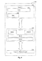
- FIG. 4 is a block diagram illustrating an embodiment of a protocol stack apparatus.
- the RRC block 200 is a sub layer of Layer 3 130 of a UMTS protocol stack 100 .
- the RRC 200 exists in the control plane only and provides an information transfer service to the non-access stratum NAS 134 .
- the RRC 200 is responsible for controlling the configuration of radio interface Layer 1 110 and Layer 2 120 .
- the RRC 200 layer of the UE decodes this message and initiates the appropriate RRC procedure.
- FIG. 5A is a flowchart that illustrates a first embodiment implemented on a UE device.
- the UE has configured the PCH (for UEs in Idle, Cell_PCH and Ura_PCH states) or FACH (UEs in Cell_FACH state) (step 502 )
- the MIB is re-read by the UE (step 504 ). If the value tag of the MIB is different from the value tag of the previous MIB (for instance as stored by the UE when selecting the cell) (step 506 ), the UE acquires the updated system information blocks (step 508 ). If the value tags are identical (step 506 ), no further action is necessary.
- the MIB is re-read at intervals during the maximum possible deferral period. This is illustrated in FIG. 5B .
- a Deferred System Information Change timer is started (step 503 ).
- the MIB is then read (step 504 ) and the value tag of the MIB and that stored in the UE are compared (step 506 ). If the Value tags are different then the UE acquires the updated System Information (step 508 ).
- the UE determines whether the Deferred System Information Change timer is still running (step 510 ). If the Deferred System Information Change timer has not yet expired, the MIB is re-read (step 504 ). If the timer has expired, then the process ends.
- a typical value for the period of the Deferred System Information Change timer is 40.96 seconds i.e. one system information transmission cycle.
- the UE may be arranged to read every MIB broadcast during the period set by the Deferred System Information Change timer or a subset of the MIBs broadcast in this period.
- FIG. 6A is a flowchart that illustrates an embodiment implemented in the UTRAN rather than at the UE.
- the UTRAN broadcasts a notification of the intent to change system information (for instance, in a PAGING TYPE 1 /SYSTEM INFORMATION CHANGE INDICATION message) a first time (step 602 ) and then broadcasts at least one repeat of the notification of system information change in a PAGING TYPE 1 /SYSTEM INFORMATION CHANGE INDICATION message to notify a UE of the intent to change system information (step 604 ).
- the notification of system information change is sent as an Information Element (IE) “BCCH modification info” contained in a SYSTEM INFORMATION CHANGE INDICATION message transmitted on the Broadcast control channel (BCCH) mapped on at least one Forward Access Channel (FACH) on every Secondary CCPCH in the cell.
- IE Information Element
- BCCH Broadcast control channel
- FACH Forward Access Channel
- the UTRAN may be arranged to repeat more than once the notification of the intent to change system information.
- One example of the time period between the repeat transmissions is a time period comparable with the maximum time for the UE to configure the PCH/FACH channel after reading system information prior to selecting the cell (e.g. 500 ms).
- each UE should then receive at least one notification of the intent to change system information as sent in the PAGING TYPE 1 /SYSTEM INFORMATION CHANGE INDICATION messages.
- the UTRAN may repeat transmission of the notification of the intent to change system information in a PAGING TYPE 1 or a SYSTEM INFORMATION CHANGE INDICATION message to a UE to increase the probability of proper reception of notification of the intent to change system information.
- the UTRAN may repeat the PAGING TYPE 1 /SYSTEM INFORMATION CHANGE INDICATION messages up to the time the change occurs.
- the repeat of the notification of system information change is sent by the UTRAN at a time close to the intended change in the system information.
- the repeat is sent in a time interval prior to the time at which the system information is to be changed.
- TTI Transmission Time Interval
- a Transmission Time Interval is defined which is the inter-arrival time of a TBS (Transport Block Set), and is equal to the periodicity at which a Transport Block Set is transferred by the physical layer on the radio interface. It is a multiple of the minimum interleaving period (e.g. 10 ms, the length of one RF (Radio Frame)).
- the MAC (Medium Access Control) in Layer 2 120 delivers one Transport Block Set to the physical layer 110 every TTI.
- the repeat of the notification of system information change is sent in a TTI that occurs before the system change is to be implemented.
- the repeat may be sent in the TTI (X ⁇ 1) immediately before the TTI (X) in which the system information is to be changed.
- This implementation is particularly applicable for sending SYSTEM INFORMATION CHANGE INDICATION on one or more FACHs, as a UE in the Cell_FACH RRC state continuously monitors its configured FACH(s) for messages.
- the repeat may be sent in a TTI (X ⁇ n) before the TTI (X) in which the system information is to be changed, where the TTI (X ⁇ n) represents a TTI to which the particular UE will listen by default.
- TTI X ⁇ n
- the repeat may be sent in any of these time intervals that occur before the system change is to be implemented. The UE will therefore by default listen at the required time interval.
- DRX Discontinuous Reception
- FIG. 6B illustrates an embodiment at the UTRAN for a notification of system information change sent in a PAGING TYPE 1 /SYSTEM INFORMATION CHANGE INDICATION message.
- This embodiment addresses notification of deferred changes by the UTRAN.
- the UE may be arranged to address loss of notification of non-deferred changes as described above.
- the UTRAN broadcasts a notification of the intent to change system information (for instance, in a PAGING TYPE 1 /SYSTEM INFORMATION CHANGE INDICATION message) a first time (step 602 ) and then, if the notification of the intent to change system information is set for a deferred time (step 603 ), the UTRAN broadcasts at least one repeat of the notification of system information change in a PAGING TYPE 1 /SYSTEM INFORMATION CHANGE INDICATION message to notify a UE of the intent to change system information (step 604 ), the repeat of the notification of a system information change being sent within a period relative to the deferred time.
- FIG. 7 shows a timing diagram to illustrate an example of the operation of such an embodiment.
- the notification of a system information change indicates that the system information change is to be implemented by a receiving device at a deferred time T.
- the network then sends a repeat of the notification of a system information change at a time t.sub.n relative to the deferred time T.
- the repeat may be sent before or after the deferred time T.
- the repeat is sent at a time t.sub.3 equal or less than 50 seconds (which is around 5000 frames) before or after the deferred time T.
- this repeat is sent at a time t.sub.2 equal or less than 40.96 seconds (which is one cycle of 4096 frames), 10 seconds (1000 frames), 1 second (100 frames), 100 ms (10 frames) or 10 ms (1 frame).
- the repeat may be sent within the period between t.sub.1 and T or within the period between T and t.sub.4 subsequent to the deferred time T. In this latter case, the time t.sub.4 is likely to be relatively soon after T (for example 10 ms or 100 ms).
- the repeat may be sent at the deferred time T.
- this repeat message is sent (as a non-deferred change) in the latest radio frame (also known as the Transmission Timing Interval or TTI) that is (a) prior to the actual system information change, and (b) a TTI for which the UE's receiver is not switched off due to discontinuous reception (DRX).
- the radio frame used may be limited by DRX (discontinuous reception).
- DRX discontinuous reception
- the exact timing of the repeat message may be affected by other message traffic on the FACH.
- the repeat message will be received and the UE can then acquire the updated system information when it is available.
- the UTRAN repeats the transmission of the notification of a system information change to increase the probability of proper reception by the UE of notification of the intent to change system information by the UE.
- the UTRAN may be arranged to send the repeat of the notification of a system information change at a predetermined time.
- suitable times are as follows: within one frame (before or after) of the frame in which the system change is to be implemented; within 10 frames before or after; within 100 frames before or after; within 1000 frames before or after; within 4000 frames before or after.
- the benefits of the technique may reduce as the time period between the repeat of the notification of a system information change and the deferred time of the system information change increases.
- the technique relates to sending a repeat of the notification of a system information change at a time that is close enough to the time of implementation of the system information change as to still be of use to the UE.
- the UE does not need to be continuously monitoring the MIB looking for system information changes, which should result in a prolonged battery life for the UE. It is not important here that the time is predetermined for the UTRAN, merely that the UTRAN is going to repeat the message.
- FIGS. 5A and 5B illustrate embodiments implemented in the UE and FIGS. 6A and 6B illustrate embodiments implemented in the network
- the network may be arranged to send repeat transmissions of the notifications of system information changes and the user equipment may be arranged to re-read broadcast system information whenever it re-configures itself.
- One preferred solution is the implementation described in FIG. 5A for the UE, together with the implementation described in FIG. 6B for the network.
- FIG. 8 is a block diagram illustrating a mobile device, which can act as a UE and co-operate with the apparatus and methods of FIGS. 1 to 7 , and which is an exemplary wireless communication device.
- Mobile station 800 is preferably a two-way wireless communication device having at least voice and data communication capabilities.
- Mobile station 800 preferably has the capability to communicate with other computer systems on the Internet.
- the wireless device may be referred to as a data messaging device, a two-way pager, a wireless e-mail device, a cellular telephone with data messaging capabilities, a wireless Internet appliance, or a data communication device, as examples.
- mobile station 800 is enabled for two-way communication, it will incorporate a communication subsystem 811 , including both a receiver 812 and a transmitter 814 , as well as associated components such as one or more, preferably embedded or internal, antenna elements 816 and 818 , local oscillators (LOs) 813 , and a processing module such as a digital signal processor (DSP) 820 .
- LOs local oscillators
- DSP digital signal processor
- mobile station 800 may include a communication subsystem 811 designed to operate within the MobitexTM. mobile communication system, the DataTACTM. mobile communication system, GPRS network, UMTS network, or EDGE network.
- Network access requirements will also vary depending upon the type of network 802 .
- mobile station 800 is registered on the network using a unique identification number associated with each mobile station.
- network access is associated with a subscriber or user of mobile station 800 .
- a GPRS mobile station therefore requires a subscriber identity module (SIM) card in order to operate on a GPRS network. Without a valid SIM card, a GPRS mobile station will not be fully functional. Local or non-network communication functions, as well as legally required functions (if any) such as “911” emergency calling, may be available, but mobile station 800 will be unable to carry out any other functions involving communications over the network 802 .
- SIM subscriber identity module
- the SIM interface 844 is normally similar to a card-slot into which a SIM card can be inserted and ejected like a diskette or PCMCIA card.
- the SIM card can have approximately 64K of memory and hold many key configuration 851 , and other information 853 such as identification, and subscriber related information.
- mobile station 800 may send and receive communication signals over the network 802 .
- Signals received by antenna 816 through communication network 802 are input to receiver 812 , which may perform such common receiver functions as signal amplification, frequency down conversion, filtering, channel selection and the like, and in the example system shown in FIG. 8 , analog to digital (A/D) conversion.
- A/D conversion of a received signal allows more complex communication functions such as demodulation and decoding to be performed in the DSP 820 .
- signals to be transmitted are processed, including modulation and encoding for example, by DSP 820 and input to transmitter 814 for digital to analog conversion, frequency up conversion, filtering, amplification and transmission over the communication network 802 via antenna 818 .
- DSP 820 not only processes communication signals, but also provides for receiver and transmitter control. For example, the gains applied to communication signals in receiver 812 and transmitter 814 may be adaptively controlled through automatic gain control algorithms implemented in DSP 820 .
- Mobile station 800 preferably includes a microprocessor 838 which controls the overall operation of the device. Communication functions, including at least data and voice communications, are performed through communication subsystem 811 . Microprocessor 838 also interacts with further device subsystems such as the display 822 , flash memory 824 , random access memory (RAM) 826 , auxiliary input/output (I/O) subsystems 828 , serial port 830 , keyboard 832 , speaker 834 , microphone 836 , a short-range communications subsystem 840 and any other device subsystems generally designated as 842 .
- a microprocessor 838 which controls the overall operation of the device. Communication functions, including at least data and voice communications, are performed through communication subsystem 811 . Microprocessor 838 also interacts with further device subsystems such as the display 822 , flash memory 824 , random access memory (RAM) 826 , auxiliary input/output (I/O) subsystems 828 , serial port 830 , keyboard 832 , speaker 834
- Some of the subsystems shown in FIG. 8 perform communication-related functions, whereas other subsystems may provide “resident” or on-device functions.
- some subsystems such as keyboard 832 and display 822 , for example, may be used for both communication-related functions, such as entering a text message for transmission over a communication network, and device-resident functions such as a calculator or task list.
- Operating system software used by the microprocessor 838 is preferably stored in a persistent store such as flash memory 824 , which may instead be a read-only memory (ROM) or similar storage element (not shown).
- ROM read-only memory
- Those skilled in the art will appreciate that the operating system, specific device applications, or parts thereof, may be temporarily loaded into a volatile memory such as RAM 826 . Received communication signals may also be stored in RAM 826 .
- flash memory 824 can be segregated into different areas for both computer programs 858 and program data storage 850 , 852 , 854 and 856 . These different storage types indicate that each program can allocate a portion of flash memory 824 for their own data storage requirements.
- Microprocessor 838 in addition to its operating system functions, preferably enables execution of software applications on the mobile station. A predetermined set of applications that control basic operations, including at least data and voice communication applications for example, will normally be installed on mobile station 800 during manufacturing.
- a preferred software application may be a personal information manager (PIM) application having the ability to organize and manage data items relating to the user of the mobile station such as, but not limited to, e-mail, calendar events, voice mails, appointments, and task items.
- PIM personal information manager
- PIM application would preferably have the ability to send and receive data items, via the wireless network 802 .
- the PIM data items are seamlessly integrated, synchronized and updated, via the wireless network 802 , with the mobile station user's corresponding data items stored or associated with a host computer system.
- Further applications may also be loaded onto the mobile station 800 through the network 802 , an auxiliary I/O subsystem 828 , serial port 830 , short-range communications subsystem 840 or any other suitable subsystem 842 , and installed by a user in the RAM 826 or preferably a non-volatile store (not shown) for execution by the microprocessor 838 .
- Such flexibility in application installation increases the functionality of the device and may provide enhanced on-device functions, communication-related functions, or both.
- secure communication applications may enable electronic commerce functions and other such financial transactions to be performed using the mobile station 800 .
- a received signal such as a text message or web page download will be processed by the communication subsystem 811 and input to the microprocessor 838 , which preferably further processes the received signal for output to the display 822 , or alternatively to an auxiliary I/O device 828 .
- a user of mobile station 800 may also compose data items such as email messages for example, using the keyboard 832 , which is preferably a complete alphanumeric keyboard or telephone-type keypad, in conjunction with the display 822 and possibly an auxiliary I/O device 828 . Such composed items may then be transmitted over a communication network through the communication subsystem 811 .
- mobile station 800 For voice communications, overall operation of mobile station 800 is similar, except that received signals would preferably be output to a speaker 834 and signals for transmission would be generated by a microphone 836 .
- Alternative voice or audio I/O subsystems such as a voice message recording subsystem, may also be implemented on mobile station 800 .
- voice or audio signal output is preferably accomplished primarily through the speaker 834
- display 822 may also be used to provide an indication of the identity of a calling party, the duration of a voice call, or other voice call related information for example.
- Serial port 830 in FIG. 8 would normally be implemented in a personal digital assistant (PDA)-type mobile station for which synchronization with a user's desktop computer (not shown) may be desirable, but is an optional device component.
- PDA personal digital assistant
- Such a port 830 would enable a user to set preferences through an external device or software application and would extend the capabilities of mobile station 800 by providing for information or software downloads to mobile station 800 other than through a wireless communication network.
- the alternate download path may for example be used to load an encryption key onto the device through a direct and thus reliable and trusted connection to thereby enable secure device communication.
- Other communications subsystems 840 such as a short-range communications subsystem, is a further optional component which may provide for communication between mobile station 800 and different systems or devices, which need not necessarily be similar devices.
- the subsystem 840 may include an infrared device and associated circuits and components or a BluetoothTM. communication module to provide for communication with similarly enabled systems and devices.
- protocol stacks 846 include apparatus and a method for handling messages that relate to a cell other than the currently operating cell in universal mobile telecommunications system user equipment.
Abstract
Description
Claims (13)
Priority Applications (1)
| Application Number | Priority Date | Filing Date | Title |
|---|---|---|---|
| US13/178,309 US8526962B2 (en) | 2004-01-09 | 2011-07-07 | Apparatus, and method, for implementing detection of system information changes in universal mobile telecommunications systems |
Applications Claiming Priority (4)
| Application Number | Priority Date | Filing Date | Title |
|---|---|---|---|
| US10/754,735 US7346353B2 (en) | 2004-01-09 | 2004-01-09 | Apparatus and method for implementing detection of system information changes in universal mobile telecommunications systems |
| EP04250097A EP1553797B8 (en) | 2004-01-09 | 2004-01-09 | Apparatus and method for implementing detection of system information changes in universal mobile telecommunications systems |
| US12/050,352 US8000713B2 (en) | 2004-01-09 | 2008-03-18 | Apparatus and method for implementing detection of system information changes in universal mobile telecommunications systems |
| US13/178,309 US8526962B2 (en) | 2004-01-09 | 2011-07-07 | Apparatus, and method, for implementing detection of system information changes in universal mobile telecommunications systems |
Related Parent Applications (1)
| Application Number | Title | Priority Date | Filing Date |
|---|---|---|---|
| US12/050,352 Continuation US8000713B2 (en) | 2004-01-09 | 2008-03-18 | Apparatus and method for implementing detection of system information changes in universal mobile telecommunications systems |
Publications (2)
| Publication Number | Publication Date |
|---|---|
| US20110269443A1 US20110269443A1 (en) | 2011-11-03 |
| US8526962B2 true US8526962B2 (en) | 2013-09-03 |
Family
ID=34863118
Family Applications (3)
| Application Number | Title | Priority Date | Filing Date |
|---|---|---|---|
| US10/754,735 Active 2025-01-22 US7346353B2 (en) | 2004-01-09 | 2004-01-09 | Apparatus and method for implementing detection of system information changes in universal mobile telecommunications systems |
| US12/050,352 Active 2026-01-03 US8000713B2 (en) | 2004-01-09 | 2008-03-18 | Apparatus and method for implementing detection of system information changes in universal mobile telecommunications systems |
| US13/178,309 Active 2024-06-08 US8526962B2 (en) | 2004-01-09 | 2011-07-07 | Apparatus, and method, for implementing detection of system information changes in universal mobile telecommunications systems |
Family Applications Before (2)
| Application Number | Title | Priority Date | Filing Date |
|---|---|---|---|
| US10/754,735 Active 2025-01-22 US7346353B2 (en) | 2004-01-09 | 2004-01-09 | Apparatus and method for implementing detection of system information changes in universal mobile telecommunications systems |
| US12/050,352 Active 2026-01-03 US8000713B2 (en) | 2004-01-09 | 2008-03-18 | Apparatus and method for implementing detection of system information changes in universal mobile telecommunications systems |
Country Status (7)
| Country | Link |
|---|---|
| US (3) | US7346353B2 (en) |
| EP (1) | EP1553797B8 (en) |
| AT (1) | ATE363188T1 (en) |
| CA (1) | CA2491809C (en) |
| DE (1) | DE602004006594T2 (en) |
| ES (1) | ES2287647T3 (en) |
| HK (1) | HK1078230B (en) |
Families Citing this family (55)
| Publication number | Priority date | Publication date | Assignee | Title |
|---|---|---|---|---|
| DE202005021930U1 (en) | 2005-08-01 | 2011-08-08 | Corning Cable Systems Llc | Fiber optic decoupling cables and pre-connected assemblies with toning parts |
| US8817737B2 (en) * | 2005-10-31 | 2014-08-26 | Lg Electronics Inc. | Method of transmitting and receiving data in a mobile communication network |
| JP4818371B2 (en) * | 2005-10-31 | 2011-11-16 | エルジー エレクトロニクス インコーポレイティド | Method for processing control information in wireless mobile communication system |
| EP1943777B1 (en) | 2005-10-31 | 2016-07-20 | LG Electronics Inc. | Method for processing control information in a wireless mobile communication system |
| US7949377B2 (en) | 2005-12-14 | 2011-05-24 | Research In Motion Limited | Method and apparatus for user equipment directed radio resource control in a UMTS network |
| US8265034B2 (en) | 2006-05-17 | 2012-09-11 | Research In Motion Limited | Method and system for a signaling connection release indication |
| EP1858209B1 (en) | 2006-05-17 | 2010-10-13 | Research In Motion Limited | Method and system for a signaling connection release indication in an UMTS network |
| US20080049662A1 (en) * | 2006-08-25 | 2008-02-28 | Research In Motion Limited | Apparatus, and associated method, for releasing a data-service radio resource allocated to a data-service-capable mobile node |
| GB2446738C (en) * | 2007-02-02 | 2014-10-01 | Ubiquisys Ltd | Basestation measurement modes |
| KR101479340B1 (en) * | 2007-09-18 | 2015-01-06 | 엘지전자 주식회사 | Method for performing cell reselection procedure in wireless communication system |
| KR20090029623A (en) * | 2007-09-18 | 2009-03-23 | 엘지전자 주식회사 | Method for acquiring system information in wireless communication |
| KR101382748B1 (en) * | 2008-01-25 | 2014-04-08 | 엘지전자 주식회사 | Method for performing random access process in wireless communication system |
| JP5103113B2 (en) | 2007-09-21 | 2012-12-19 | 株式会社エヌ・ティ・ティ・ドコモ | User equipment |
| ES2385415T3 (en) * | 2007-11-13 | 2012-07-24 | Research In Motion Limited | Method and apparatus for state / mode transition |
| JP5015856B2 (en) * | 2008-02-01 | 2012-08-29 | パナソニック株式会社 | Base station, radio communication system, and handover method |
| US8599802B2 (en) * | 2008-03-14 | 2013-12-03 | Interdigital Patent Holdings, Inc. | Method and apparatus to deliver public warning messages |
| US8730010B2 (en) * | 2008-03-18 | 2014-05-20 | Lg Electronics Inc. | Method of receiving a disaster warning message using a paging message in mobile communication system |
| EP2292034B1 (en) * | 2008-05-02 | 2016-02-10 | Nokia Solutions and Networks Oy | Method, system, base station and signal for communicating planned future cell system information in a radio telecommunication network |
| CN106304289B (en) * | 2008-06-13 | 2019-10-22 | 华为技术有限公司 | A kind of method, apparatus and system of indicating discontinuous dispatching data |
| US8457618B2 (en) | 2008-06-20 | 2013-06-04 | Motorola Mobility Llc | Preventing random access based on outdated system information in a wireless communication system |
| GB2461845B (en) * | 2008-06-27 | 2012-05-16 | Ubiquisys Ltd | Scrambling code selection |
| KR101556417B1 (en) * | 2008-09-08 | 2015-10-02 | 엘지전자 주식회사 | Method of checking change of system information in wireless communication system |
| KR20100033353A (en) * | 2008-09-19 | 2010-03-29 | 엘지전자 주식회사 | Method of transmitting or receiving an updated warning message in mobile communication system |
| EP3641410B1 (en) * | 2008-11-10 | 2021-08-25 | BlackBerry Limited | Method and apparatus of transition to a battery efficient state or configuration by indicating end of data transmission |
| CN101998510A (en) * | 2009-08-21 | 2011-03-30 | 中兴通讯股份有限公司 | Base station and method for storing system information code stream |
| KR101618782B1 (en) * | 2009-08-24 | 2016-05-12 | 엘지전자 주식회사 | Method of updating BS System Information of a Relay Station in a Broadband Wireless Access System |
| US8229412B2 (en) * | 2009-10-02 | 2012-07-24 | Sharp Laboratories Of America, Inc. | Determining whether system information can be reused and managing system information in a wireless communication system |
| AU2010321205B2 (en) | 2009-11-23 | 2014-09-04 | Blackberry Limited | State or mode transition triggering based on SRI message transmission |
| CA2781558C (en) | 2009-11-23 | 2021-06-29 | Research In Motion Limited | Method and apparatus for state/mode transitioning |
| CA3038940C (en) | 2009-11-23 | 2021-04-27 | Blackberry Limited | Method and apparatus for state/mode transitioning |
| MX2012005874A (en) * | 2009-11-24 | 2012-11-30 | Research In Motion Ltd | Method and apparatus for state/mode transitioning. |
| US8983532B2 (en) * | 2009-12-30 | 2015-03-17 | Blackberry Limited | Method and system for a wireless communication device to adopt varied functionalities based on different communication systems by specific protocol messages |
| JP5551275B2 (en) * | 2010-02-10 | 2014-07-16 | ブラックベリー リミテッド | Method and apparatus for status / mode transmission |
| PT2656664T (en) | 2010-12-20 | 2017-03-31 | ERICSSON TELEFON AB L M (publ) | Methods and nodes for setting values of system parameters used in a wireless communication system |
| CN103563315A (en) * | 2011-04-01 | 2014-02-05 | 英特尔公司 | Multi-stream joint transmission scheme for wireless communication network |
| WO2013105914A2 (en) | 2011-04-01 | 2013-07-18 | Intel Corporation | System acquisition mechanism for fixed devices in mobile broadband networks |
| WO2012147049A1 (en) * | 2011-04-28 | 2012-11-01 | Renesas Mobile Corporation | Cellular communications system |
| KR20140040808A (en) * | 2011-07-14 | 2014-04-03 | 엘지전자 주식회사 | Method for reporting in wireless communication system and apparatus for supporting same |
| CA2823789C (en) | 2011-11-11 | 2016-08-16 | Research In Motion Limited | Method and apparatus for user equipment state transition |
| US20140370835A1 (en) * | 2013-06-14 | 2014-12-18 | Htc Corporation | Method of Handling Radio Resource Control Connection Establishment during Reception of Public Warning System Message in Wireless Communication System and Communication Device Thereof |
| US20150092672A1 (en) * | 2013-09-30 | 2015-04-02 | Qualcomm Incorporated | System information for wireless communications systems with flexible bandwidth carrier |
| US9392601B2 (en) * | 2013-09-30 | 2016-07-12 | Qualcomm Incorporated | Techniques for determining whether to utilize system information between multiple bandwidth carriers |
| US20150215860A1 (en) * | 2014-01-30 | 2015-07-30 | Qualcomm Incorporated | Subscription acquisition time |
| EP3226622B1 (en) | 2014-01-31 | 2018-06-13 | Fujitsu Limited | Access method of wireless communication network |
| US9538455B2 (en) * | 2014-02-04 | 2017-01-03 | Qualcomm Incorporated | Techniques for reading system information in wireless communications |
| US10616822B2 (en) | 2015-02-10 | 2020-04-07 | Qualcomm Incorporated | System information updating |
| US10200920B2 (en) * | 2015-02-10 | 2019-02-05 | Qualcomm Incorporated | On-demand system information |
| US20180255606A1 (en) * | 2015-10-06 | 2018-09-06 | Lg Electronics Inc. | Method for updating system information in wireless communication system and apparatus therefor |
| WO2017155291A2 (en) * | 2016-03-08 | 2017-09-14 | Lg Electronics Inc. | Method for providing system information to remote ue in wireless communication system and apparatus therefor |
| EP4096263B1 (en) * | 2016-10-07 | 2023-09-06 | FG Innovation Company Limited | Method and apparatus for system information delivery |
| EP3549370B1 (en) * | 2016-12-05 | 2021-10-27 | LG Electronics Inc. | Method for processing system information for machine-type communication system and a device therefor |
| WO2018195981A1 (en) * | 2017-04-28 | 2018-11-01 | 北京小米移动软件有限公司 | Method and apparatus for giving notification of system information modification, and computer-readable storage medium |
| CN108809491B (en) * | 2017-05-04 | 2020-02-18 | 维沃移动通信有限公司 | System information transmission method, terminal and network side equipment |
| WO2019193395A1 (en) | 2018-04-04 | 2019-10-10 | Nokia Technologies Oy | Management of system information area |
| US11659380B1 (en) | 2021-05-05 | 2023-05-23 | T-Mobile Usa, Inc. | UE-capability-based system information block transmission |
Citations (4)
| Publication number | Priority date | Publication date | Assignee | Title |
|---|---|---|---|---|
| US5404355A (en) | 1992-10-05 | 1995-04-04 | Ericsson Ge Mobile Communications, Inc. | Method for transmitting broadcast information in a digital control channel |
| WO2000072609A1 (en) | 1999-05-20 | 2000-11-30 | Telefonaktiebolaget L M Ericsson (Publ) | Method and apparatus for broadcasting system information in a cellular communications network |
| US20040166891A1 (en) | 2002-12-20 | 2004-08-26 | Mahkonen Marko K. | Method and apparatus for controlling communication between user equipment and a base station in a radio access network |
| US20050148349A1 (en) | 2003-12-19 | 2005-07-07 | Padmaja Putcha | Cell selection on transitioning from dedicated mode in wireless communications devices |
-
2004
- 2004-01-09 AT AT04250097T patent/ATE363188T1/en not_active IP Right Cessation
- 2004-01-09 EP EP04250097A patent/EP1553797B8/en not_active Expired - Lifetime
- 2004-01-09 ES ES04250097T patent/ES2287647T3/en not_active Expired - Lifetime
- 2004-01-09 US US10/754,735 patent/US7346353B2/en active Active
- 2004-01-09 DE DE602004006594T patent/DE602004006594T2/en not_active Expired - Lifetime
-
2005
- 2005-01-07 CA CA2491809A patent/CA2491809C/en active Active
-
2006
- 2006-01-04 HK HK06100178.8A patent/HK1078230B/en not_active IP Right Cessation
-
2008
- 2008-03-18 US US12/050,352 patent/US8000713B2/en active Active
-
2011
- 2011-07-07 US US13/178,309 patent/US8526962B2/en active Active
Patent Citations (5)
| Publication number | Priority date | Publication date | Assignee | Title |
|---|---|---|---|---|
| US5404355A (en) | 1992-10-05 | 1995-04-04 | Ericsson Ge Mobile Communications, Inc. | Method for transmitting broadcast information in a digital control channel |
| WO2000072609A1 (en) | 1999-05-20 | 2000-11-30 | Telefonaktiebolaget L M Ericsson (Publ) | Method and apparatus for broadcasting system information in a cellular communications network |
| US6628946B1 (en) * | 1999-05-20 | 2003-09-30 | Telefonaktiebolaget Lm Ericsson (Publ) | Method and apparatus for broadcasting system information in a cellular communications network |
| US20040166891A1 (en) | 2002-12-20 | 2004-08-26 | Mahkonen Marko K. | Method and apparatus for controlling communication between user equipment and a base station in a radio access network |
| US20050148349A1 (en) | 2003-12-19 | 2005-07-07 | Padmaja Putcha | Cell selection on transitioning from dedicated mode in wireless communications devices |
Also Published As
| Publication number | Publication date |
|---|---|
| US20110269443A1 (en) | 2011-11-03 |
| US7346353B2 (en) | 2008-03-18 |
| ES2287647T3 (en) | 2007-12-16 |
| HK1078230B (en) | 2007-09-28 |
| EP1553797B1 (en) | 2007-05-23 |
| CA2491809C (en) | 2010-09-21 |
| EP1553797A1 (en) | 2005-07-13 |
| HK1078230A1 (en) | 2006-03-03 |
| US20050153700A1 (en) | 2005-07-14 |
| US20080160981A1 (en) | 2008-07-03 |
| DE602004006594D1 (en) | 2007-07-05 |
| CA2491809A1 (en) | 2005-07-09 |
| ATE363188T1 (en) | 2007-06-15 |
| EP1553797B8 (en) | 2008-07-02 |
| US8000713B2 (en) | 2011-08-16 |
| DE602004006594T2 (en) | 2008-01-31 |
Similar Documents
| Publication | Publication Date | Title |
|---|---|---|
| US8526962B2 (en) | Apparatus, and method, for implementing detection of system information changes in universal mobile telecommunications systems | |
| CA2492001C (en) | Apparatus and method for implementing notification of system information changes in universal mobile telecommunications systems | |
| US20050164683A1 (en) | Apparatus and method for implementing notification of system information changes in universal mobile telecommunications systems | |
| US7444142B2 (en) | Apparatus and method for implementing system information acquisition in universal mobile telecommunications system user equipment | |
| CA2495928C (en) | Apparatus and method for implementing system information acquisition in universal mobile telecommunications system user equipment | |
| US9100893B2 (en) | Method for cell selection in a radio access network | |
| US7996010B2 (en) | Apparatus and method for querying for RAT handover system information in mobile telecommunications systems | |
| US8073453B2 (en) | Apparatus and method for handling system information in mobile telecommunications system user equipment | |
| US20090298459A1 (en) | Apparatus and Method for Handling Out of Service Emergency Calls in Wireless Telecommunications System User Equipment | |
| CA2665661C (en) | Method and apparatus for transitioning from a first rat to a second rat | |
| US9282503B2 (en) | Apparatus and method for handling broadcast system information in telecommunications system user equipment | |
| US20120064877A1 (en) | Method and Apparatus Having Improved Handling of State Transitions | |
| CA2495921C (en) | Apparatus and method for operating a communications device in a mobile communications network | |
| CA2567018C (en) | Apparatus and method for querying for rat handover system information in mobile telecommunications systems | |
| US20120040669A1 (en) | Method and Apparatus for Handling URA Information | |
| EP2418912A1 (en) | Method and apparatus for handling URA information for a wireless communication device | |
| CA2546041C (en) | Method and apparatus for controlling traffic volume measurement validity in a universal mobile telecommunications system |
Legal Events
| Date | Code | Title | Description |
|---|---|---|---|
| AS | Assignment |
Owner name: RESEARCH IN MOTION LIMITED, CANADA Free format text: ASSIGNMENT OF ASSIGNORS INTEREST;ASSIGNOR:M-STACK LIMITED;REEL/FRAME:026557/0642 Effective date: 20110502 Owner name: M-STACK LIMITED, UNITED KINGDOM Free format text: ASSIGNMENT OF ASSIGNORS INTEREST;ASSIGNORS:FARNSWORTH, ANDREW JOHN;ROBERTS, GIDEON;REEL/FRAME:026557/0582 Effective date: 20040514 |
|
| STCF | Information on status: patent grant |
Free format text: PATENTED CASE |
|
| AS | Assignment |
Owner name: BLACKBERRY LIMITED, ONTARIO Free format text: CHANGE OF NAME;ASSIGNOR:RESEARCH IN MOTION LIMITED;REEL/FRAME:032471/0734 Effective date: 20130709 |
|
| FPAY | Fee payment |
Year of fee payment: 4 |
|
| MAFP | Maintenance fee payment |
Free format text: PAYMENT OF MAINTENANCE FEE, 8TH YEAR, LARGE ENTITY (ORIGINAL EVENT CODE: M1552); ENTITY STATUS OF PATENT OWNER: LARGE ENTITY Year of fee payment: 8 |
|
| AS | Assignment |
Owner name: MALIKIE INNOVATIONS LIMITED, IRELAND Free format text: ASSIGNMENT OF ASSIGNORS INTEREST;ASSIGNOR:BLACKBERRY LIMITED;REEL/FRAME:064104/0103 Effective date: 20230511 |
|
| AS | Assignment |
Owner name: MALIKIE INNOVATIONS LIMITED, IRELAND Free format text: NUNC PRO TUNC ASSIGNMENT;ASSIGNOR:BLACKBERRY LIMITED;REEL/FRAME:064066/0001 Effective date: 20230511 |