US852012A - Charging-truck for annealing-furnaces. - Google Patents
Charging-truck for annealing-furnaces. Download PDFInfo
- Publication number
- US852012A US852012A US26980605A US1905269806A US852012A US 852012 A US852012 A US 852012A US 26980605 A US26980605 A US 26980605A US 1905269806 A US1905269806 A US 1905269806A US 852012 A US852012 A US 852012A
- Authority
- US
- United States
- Prior art keywords
- truck
- frame
- annealing
- air
- cylinder
- Prior art date
- Legal status (The legal status is an assumption and is not a legal conclusion. Google has not performed a legal analysis and makes no representation as to the accuracy of the status listed.)
- Expired - Lifetime
Links
Images

Classifications
-
- B—PERFORMING OPERATIONS; TRANSPORTING
- B66—HOISTING; LIFTING; HAULING
- B66F—HOISTING, LIFTING, HAULING OR PUSHING, NOT OTHERWISE PROVIDED FOR, e.g. DEVICES WHICH APPLY A LIFTING OR PUSHING FORCE DIRECTLY TO THE SURFACE OF A LOAD
- B66F3/00—Devices, e.g. jacks, adapted for uninterrupted lifting of loads
- B66F3/24—Devices, e.g. jacks, adapted for uninterrupted lifting of loads fluid-pressure operated
Definitions
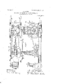
- Fi 'urel is a toplan View of my extensible device for supp yin compressed air to my truck; Fig. 2, a' side e evation of the same;
- FIG. 3 an end elevation of the same, the rail and air-hose, hereinafter referred to, being shown in cross-section;
- Fig. 4 a top-plan view of my truck, and
- Fig. 5 a side elevation of the same, one of the driving-wheels, hereinafter referred to, being removed.
- 1-1 are two horizontal I-beams secured in parallel relation and which form the bed or frame of my truck.
- One end of th's bed is pivotally supported, as at 2, upon a steering-wheel 3, provided with a steermg-handle 4.
- a seat 5 for the operator.
- a pair of driving-wheels 66 mounted upon the ends F. .1, of shaft 1.
- 1s I a sleeve 8 from which springs vertically a i pistonq'od O, carrying at its top a piston or 5 plunger (not shown in the drawings,) movf able vertically incyhnder 10.
- I llanged head ll at the top of the cylinder,
- valve 24 is an air-pipe connected with the cylinder 10 by means of branch 25 and with the cylinders of the air-engine 21 by means of branch 26.
- a valve 27 controlling the admission of air to the engines 21, also avalve 28 controlling the admission of air to the cylinder 10.
- These valves are 0 ;erated by means within convenient reach 0 the operator.
- I l I l i Ai'r being admitted to the air-engine which is supplied with reversing mechanism, (not illustrated, but which will be understood without explanation) the driving-wheels are caused to travel in the desired direction, the truck being steered by means otlthe steeringwheel and crank 3-4.
- the truck being driven with its forward arms 14'u'nder a bench ol llasks, air is admitted to the cylinder 10 which 1 ingwheel for the truck, apiston and cylinder 60 is now lifted, carrying with it through the rods 12, the forward end of the bed or frame l1.
- a charging truck a horizontal frame, a pair of drivingwheelsat one end of the frame, a steering wheel at the other end of the frame, an axle for the driving wheels, a pis- 7 ton supported upon the axle, a cylinder upon the piston, connections between the cylinder and the frame, an engine on the truck connected with the driving wheels, and extensible means, adapted for connection with said 75 cylinder and With'said engine, for conveying power from a stationary'source.
Description
PATENTED APR. 30. 1907.
J. G. BLUM. CHARGING TRUCK FOR ANNEALING FURNACES.
I 2 SHEETS-SHEET 1.
APPLICATION FILED JULY f5. 1905.
WITNESSES WW Q. 27.
PATENTED APR. 80, 1907. J. G. BLUM.
CHARGING TRUCK FOR ANNEALING FURNACES.
APPLICATION FILED JULYlS, 1905.
1111 m 11:11 mun [mum] m-w 2,5 IJI HIHHHHIIHIHHII W/ TNESS 55.:
2 SHEETS-SHEET 2.
JOHN GEORGE BLUM, OF TOLEDQOHIO.
CHARGINGv-TRUCK Foe no. 852,012. Specification of PATENT QFFICE.
ANNEALING-FURNACES.
Letters Patent. Patented April 30, 1907.
Annlication filed July 15,1905. Serial 110.269.806-
Be it khown that .l, Jonx (motion Burn, a
citizen of the United States, residing at "loledo, 1n the county of Lucas and State of Ohio, have invented certain new and useful 1 Improvements in Clntrginglrurks for Annealing-Furnaces; and I do declare the following to be a full, clear, and exact (lescriotion of the invention, such as will enable others skilled in the art to which it appertains to make and use the same, reference being bad to the accompanying drawings, and to the letters and figures of reference marked there on, which form a part of this specification.
ln malleable iron worksa mostlaborious and difficult task is the removing of the heavy flasks containing the annealed iron articles from the hot ovens after the ovens have been opened to beemptied and refilled. The
'flasks are heavy and the tern crature of the ovens so high that it can only e borne by the workmen for a moment.
' room. I attain these ob ects by means of the devices, mechanisms and arrangement of arts hereinafter described and shown, and illustrated in the accompanying drawings, in which Fi 'urel is a toplan View of my extensible device for supp yin compressed air to my truck; Fig. 2, a' side e evation of the same;
Fig. 3, an end elevation of the same, the rail and air-hose, hereinafter referred to, being shown in cross-section; Fig. 4,. a top-plan view of my truck, and Fig. 5, a side elevation of the same, one of the driving-wheels, hereinafter referred to, being removed.
Inthe drawings, 1-1 are two horizontal I-beams secured in parallel relation and which form the bed or frame of my truck. One end of th's bed is pivotally supported, as at 2, upon a steering-wheel 3, provided with a steermg-handle 4. At this end of the frame or bed is a seat 5 for the operator. At the opposite end of the bed or rame is a pair of driving-wheels 66 mounted upon the ends F. .1, of shaft 1. Upon the shaft, at its middle, 1s I a sleeve 8 from which springs vertically a i pistonq'od O, carrying at its top a piston or 5 plunger (not shown in the drawings,) movf able vertically incyhnder 10. I llanged head ll, at the top of the cylinder,
From the lead downwardly stout rods 12 which, at bottom, are connected, as at 13, with the, side bars 1, as shown. It will be seen that the frame, at this end, is sus )ended by meansof the rods 12 from the cyiinddii}, resting upon the pistonwithin the cylinder, which piston is supported by the stout iston-rod 9, engaged at its lower end witli the axle of the driving-wheel. U on the to of the beams I are secured parallerjaws S w ich engage and form guides for corresponding portions 8 on the sleeve 8.
At the end of the bed or fra'nie opposite the steering-wheel and next to the ground are horizontally projecting arms 14 disposed at such height as to conveniently slip under the low benches on which the annealing flasks are piled.
gaged by a sprocket-c ain 16 which passes over another s rocket-wheel 17,011 the-shaft 18 of a gear-w ieel 19, which is engaged and glue 21, mounted upon the frame of the true}. near to the operators seat.
22 is an n right fender or brace upon the front of the rame 1-1, supported by spring 23, designed to prevent the pile of annealing flasks upon the arms H from toppling over backward against the adjacent machinery.
24 is an air-pipe connected with the cylinder 10 by means of branch 25 and with the cylinders of the air-engine 21 by means of branch 26. In the air-pipe is a valve 27 controlling the admission of air to the engines 21, also avalve 28 controlling the admission of air to the cylinder 10. These valves are 0 ;erated by means within convenient reach 0 the operator.
A single rail 'orrod 291s suspended from tremities of'hook-shaped hangers 31. A series of carriages 3232, each having a pair of grooved Wheels 33, ride upon the rail 29. All
with an air-compressor, the other end being connected with the air-pipe 24, as at 35,-is connected with and suspended at equi-d is tantintervals from theseries of overhead Upon the shaft 7, midway between the driving-wheels, 1s a s rocket-wheel 15 en-' driven by a gear 20 on the shaft of an air-enthe cross-beams 30, of the shop, upon the ex- 'air-hose ,34,-one end of which is connected carriages 32. As the truck is moved about supported upon the axle, a cylinder in operathe shop the air-hose may be either stretched to its lull length,the carriages 32 accommodating themselves to the movement of the hose,or the hose may be shortened up so that it will hang in festoons, as illustrated in Fig. 2.
The operation of my truck is as follows:
I l I l i Ai'r being admitted to the air-engine which is supplied with reversing mechanism, (not illustrated, but which will be understood without explanation) the driving-wheels are caused to travel in the desired direction, the truck being steered by means otlthe steeringwheel and crank 3-4. The truck being driven with its forward arms 14'u'nder a bench ol llasks, air is admitted to the cylinder 10 which 1 ingwheel for the truck, apiston and cylinder 60 is now lifted, carrying with it through the rods 12, the forward end of the bed or frame l1. The bench cl flasks is now carried to the desired point in the shop, the air is permitted to escape from the cylinder 10, through the reverse movement of the valve 28, and the forward end of the frame sinks to its normal level so that the bench oi flasks rests upon the 'round. The truck is now backed away from the bench of flasks and is ready for a repetition of the above described operation. It will be seen that a bench of flasks may thus bepicked up and quickly placed in an annealing oven, or the Li uck may be rapidly driven into an annealing oven and caused to quickly pick up a bench. of flasks and to retreat with it in such time that the operator is not subjected to the usual serious inconvenience and occasional sull'cring accompanying these tasks.
Having described my invention, what I claim and desire to secure by Letters Patent near one end of the frame, a piston rigidly 1. ln acharging truck, a frame, an axle tive relation with the piston, and connections between the cylinder and frame. 2. In a charging truck, a horizontal frame, driving wheels at one end and a steering wheel at the other end of the frame, a driving i mechanism on said frame'eonnected with said driving wheels, a mechanism sulppolfted by 0 the axle of the driving wheels for raising and lo .x'ering one end of the frame, and means for connecting a stationary source of power with said two mechanisms, whereby the truck may be driven from place to place andthc 55 end of said frame raised and lowered at will.
3. In a charging truck, a horizontal frame, forwardly projecting arms secured to the front of theframe, driving wheels and asteeradapted to raise and lower the front end of the frame, a drivingrengine onthe frame connected with the driving wheels, a pipe connectcd with said cylinder and with "said drivin g engine, and means for extensibly connect- 5 5 ing said pipe with an air-compressor.
4. In a charging truck, a horizontal frame, a pair of drivingwheelsat one end of the frame, a steering wheel at the other end of the frame, an axle for the driving wheels, a pis- 7 ton supported upon the axle, a cylinder upon the piston, connections between the cylinder and the frame, an engine on the truck connected with the driving wheels, and extensible means, adapted for connection with said 75 cylinder and With'said engine, for conveying power from a stationary'source. In testimony whereof I aflix my signature in presence of ti *o witnesses.
JOHN GEORGE BLUM.
VVitne'sses: I
LOUIS SKRANSEWFKY, L. J. ANDERSON.
Priority Applications (1)
| Application Number | Priority Date | Filing Date | Title |
|---|---|---|---|
| US26980605A US852012A (en) | 1905-07-15 | 1905-07-15 | Charging-truck for annealing-furnaces. |
Applications Claiming Priority (1)
| Application Number | Priority Date | Filing Date | Title |
|---|---|---|---|
| US26980605A US852012A (en) | 1905-07-15 | 1905-07-15 | Charging-truck for annealing-furnaces. |
Publications (1)
| Publication Number | Publication Date |
|---|---|
| US852012A true US852012A (en) | 1907-04-30 |
Family
ID=2920470
Family Applications (1)
| Application Number | Title | Priority Date | Filing Date |
|---|---|---|---|
| US26980605A Expired - Lifetime US852012A (en) | 1905-07-15 | 1905-07-15 | Charging-truck for annealing-furnaces. |
Country Status (1)
| Country | Link |
|---|---|
| US (1) | US852012A (en) |
-
1905
- 1905-07-15 US US26980605A patent/US852012A/en not_active Expired - Lifetime
Similar Documents
| Publication | Publication Date | Title |
|---|---|---|
| US2281012A (en) | Industrial truck | |
| US2201189A (en) | Pneumatic automobile lift | |
| CN210419104U (en) | Lifting workbench for hull machine maintenance | |
| CN108673089A (en) | A kind of application gathering chain is directly used in the multistation assembly system of assembly | |
| US2718197A (en) | Traction vehicle having rail wheels and road wheels | |
| US2144314A (en) | Device for equalizing the vertical movement of snow removing mechanism | |
| CN106365073A (en) | Carrying accessory used for forklift | |
| US852012A (en) | Charging-truck for annealing-furnaces. | |
| US3136526A (en) | Hydraulic jack mechanism | |
| US1881169A (en) | Manipulator | |
| SE420591B (en) | DEVICE FOR A MIXED, TELESCOPIC EXTENDED LIFT STAND FOR AN ENGINE DRIVING TRUCK | |
| US697686A (en) | Portable crane. | |
| CN106276713A (en) | Fork truck carrying accessory | |
| US1503795A (en) | Automobile hoist | |
| US732142A (en) | Jack. | |
| US1179015A (en) | Pneumatic load-compensator for motor-driven vehicles. | |
| US504030A (en) | Wheel-press | |
| US2416838A (en) | Parking device | |
| US408152A (en) | Apparatus for charging and drawing furnaces | |
| US394420A (en) | Apparatus for charging and drawing furnaces | |
| US1411652A (en) | Charging truck | |
| US1355479A (en) | Hoisting-truck | |
| US1684729A (en) | Automobile elevating apparatus | |
| US686004A (en) | Radial hoist. | |
| US1024906A (en) | Apparatus for working on the upper or wearing portions of compound tram-rails. |