US8511557B2 - Labeling and authenticating using a microtag - Google Patents
Labeling and authenticating using a microtag Download PDFInfo
- Publication number
- US8511557B2 US8511557B2 US12/966,901 US96690110A US8511557B2 US 8511557 B2 US8511557 B2 US 8511557B2 US 96690110 A US96690110 A US 96690110A US 8511557 B2 US8511557 B2 US 8511557B2
- Authority
- US
- United States
- Prior art keywords
- rugate
- peak
- identifier
- spectral range
- microtag
- Prior art date
- Legal status (The legal status is an assumption and is not a legal conclusion. Google has not performed a legal analysis and makes no representation as to the accuracy of the status listed.)
- Active, expires
Links
- 238000002372 labelling Methods 0.000 title description 6
- 230000003595 spectral effect Effects 0.000 claims abstract description 56
- 238000000034 method Methods 0.000 claims description 72
- 229910052710 silicon Inorganic materials 0.000 claims description 23
- 239000010703 silicon Substances 0.000 claims description 23
- 238000012937 correction Methods 0.000 claims description 11
- 238000005530 etching Methods 0.000 description 52
- 239000010408 film Substances 0.000 description 50
- 238000000985 reflectance spectrum Methods 0.000 description 45
- VYPSYNLAJGMNEJ-UHFFFAOYSA-N Silicium dioxide Chemical compound O=[Si]=O VYPSYNLAJGMNEJ-UHFFFAOYSA-N 0.000 description 34
- 230000003287 optical effect Effects 0.000 description 34
- 238000001228 spectrum Methods 0.000 description 32
- XUIMIQQOPSSXEZ-UHFFFAOYSA-N Silicon Chemical compound [Si] XUIMIQQOPSSXEZ-UHFFFAOYSA-N 0.000 description 21
- 238000004519 manufacturing process Methods 0.000 description 18
- 229910021426 porous silicon Inorganic materials 0.000 description 18
- 239000000377 silicon dioxide Substances 0.000 description 17
- 235000012431 wafers Nutrition 0.000 description 17
- 230000006870 function Effects 0.000 description 16
- 239000011148 porous material Substances 0.000 description 16
- 230000008569 process Effects 0.000 description 15
- 238000002310 reflectometry Methods 0.000 description 14
- 230000000694 effects Effects 0.000 description 11
- 239000010410 layer Substances 0.000 description 9
- 230000008901 benefit Effects 0.000 description 8
- 238000010586 diagram Methods 0.000 description 8
- 239000000463 material Substances 0.000 description 7
- 238000001579 optical reflectometry Methods 0.000 description 6
- 238000001878 scanning electron micrograph Methods 0.000 description 6
- 238000004458 analytical method Methods 0.000 description 5
- 239000002131 composite material Substances 0.000 description 5
- 238000012545 processing Methods 0.000 description 5
- LFQSCWFLJHTTHZ-UHFFFAOYSA-N Ethanol Chemical compound CCO LFQSCWFLJHTTHZ-UHFFFAOYSA-N 0.000 description 4
- 238000003860 storage Methods 0.000 description 4
- 239000000758 substrate Substances 0.000 description 4
- 238000004422 calculation algorithm Methods 0.000 description 3
- 238000004364 calculation method Methods 0.000 description 3
- 230000008859 change Effects 0.000 description 3
- 230000008030 elimination Effects 0.000 description 3
- 238000003379 elimination reaction Methods 0.000 description 3
- 238000005259 measurement Methods 0.000 description 3
- 238000000611 regression analysis Methods 0.000 description 3
- 238000006243 chemical reaction Methods 0.000 description 2
- 238000004590 computer program Methods 0.000 description 2
- 238000013500 data storage Methods 0.000 description 2
- 230000001419 dependent effect Effects 0.000 description 2
- 238000013461 design Methods 0.000 description 2
- 238000013507 mapping Methods 0.000 description 2
- 239000011159 matrix material Substances 0.000 description 2
- 239000000203 mixture Substances 0.000 description 2
- 238000012986 modification Methods 0.000 description 2
- 230000004048 modification Effects 0.000 description 2
- 238000010606 normalization Methods 0.000 description 2
- 239000012788 optical film Substances 0.000 description 2
- 230000001590 oxidative effect Effects 0.000 description 2
- 238000004806 packaging method and process Methods 0.000 description 2
- 239000002245 particle Substances 0.000 description 2
- 230000009467 reduction Effects 0.000 description 2
- 230000004044 response Effects 0.000 description 2
- 238000007476 Maximum Likelihood Methods 0.000 description 1
- 238000013459 approach Methods 0.000 description 1
- 238000010420 art technique Methods 0.000 description 1
- 230000004888 barrier function Effects 0.000 description 1
- 230000006399 behavior Effects 0.000 description 1
- 230000005540 biological transmission Effects 0.000 description 1
- 238000004891 communication Methods 0.000 description 1
- 229910021419 crystalline silicon Inorganic materials 0.000 description 1
- 238000005520 cutting process Methods 0.000 description 1
- 238000013481 data capture Methods 0.000 description 1
- 230000003247 decreasing effect Effects 0.000 description 1
- 238000000151 deposition Methods 0.000 description 1
- 238000009792 diffusion process Methods 0.000 description 1
- 238000009826 distribution Methods 0.000 description 1
- 239000003814 drug Substances 0.000 description 1
- 229940079593 drug Drugs 0.000 description 1
- 238000003487 electrochemical reaction Methods 0.000 description 1
- 230000005518 electrochemistry Effects 0.000 description 1
- 238000000605 extraction Methods 0.000 description 1
- 230000006872 improvement Effects 0.000 description 1
- 238000007689 inspection Methods 0.000 description 1
- 238000012417 linear regression Methods 0.000 description 1
- 239000007788 liquid Substances 0.000 description 1
- 238000001459 lithography Methods 0.000 description 1
- 230000007246 mechanism Effects 0.000 description 1
- 239000002086 nanomaterial Substances 0.000 description 1
- 230000010355 oscillation Effects 0.000 description 1
- 230000003647 oxidation Effects 0.000 description 1
- 238000007254 oxidation reaction Methods 0.000 description 1
- 230000000737 periodic effect Effects 0.000 description 1
- 239000006187 pill Substances 0.000 description 1
- 239000000843 powder Substances 0.000 description 1
- 238000007781 pre-processing Methods 0.000 description 1
- 238000002360 preparation method Methods 0.000 description 1
- 238000000926 separation method Methods 0.000 description 1
- 235000012239 silicon dioxide Nutrition 0.000 description 1
- 239000002356 single layer Substances 0.000 description 1
- 238000004611 spectroscopical analysis Methods 0.000 description 1
- 238000010183 spectrum analysis Methods 0.000 description 1
- 230000000153 supplemental effect Effects 0.000 description 1
- 230000009897 systematic effect Effects 0.000 description 1
- 239000004557 technical material Substances 0.000 description 1
- 230000002123 temporal effect Effects 0.000 description 1
- 239000010409 thin film Substances 0.000 description 1
- 238000012546 transfer Methods 0.000 description 1
- 238000000411 transmission spectrum Methods 0.000 description 1
Images


Classifications
-
- G—PHYSICS
- G06—COMPUTING; CALCULATING OR COUNTING
- G06K—GRAPHICAL DATA READING; PRESENTATION OF DATA; RECORD CARRIERS; HANDLING RECORD CARRIERS
- G06K5/00—Methods or arrangements for verifying the correctness of markings on a record carrier; Column detection devices
-
- G—PHYSICS
- G06—COMPUTING; CALCULATING OR COUNTING
- G06K—GRAPHICAL DATA READING; PRESENTATION OF DATA; RECORD CARRIERS; HANDLING RECORD CARRIERS
- G06K19/00—Record carriers for use with machines and with at least a part designed to carry digital markings
- G06K19/06—Record carriers for use with machines and with at least a part designed to carry digital markings characterised by the kind of the digital marking, e.g. shape, nature, code
- G06K19/06009—Record carriers for use with machines and with at least a part designed to carry digital markings characterised by the kind of the digital marking, e.g. shape, nature, code with optically detectable marking
- G06K19/06037—Record carriers for use with machines and with at least a part designed to carry digital markings characterised by the kind of the digital marking, e.g. shape, nature, code with optically detectable marking multi-dimensional coding
-
- G—PHYSICS
- G06—COMPUTING; CALCULATING OR COUNTING
- G06K—GRAPHICAL DATA READING; PRESENTATION OF DATA; RECORD CARRIERS; HANDLING RECORD CARRIERS
- G06K19/00—Record carriers for use with machines and with at least a part designed to carry digital markings
- G06K19/06—Record carriers for use with machines and with at least a part designed to carry digital markings characterised by the kind of the digital marking, e.g. shape, nature, code
- G06K19/06009—Record carriers for use with machines and with at least a part designed to carry digital markings characterised by the kind of the digital marking, e.g. shape, nature, code with optically detectable marking
- G06K19/06046—Constructional details
- G06K19/06075—Constructional details the marking containing means for error correction
-
- G—PHYSICS
- G06—COMPUTING; CALCULATING OR COUNTING
- G06K—GRAPHICAL DATA READING; PRESENTATION OF DATA; RECORD CARRIERS; HANDLING RECORD CARRIERS
- G06K19/00—Record carriers for use with machines and with at least a part designed to carry digital markings
- G06K19/06—Record carriers for use with machines and with at least a part designed to carry digital markings characterised by the kind of the digital marking, e.g. shape, nature, code
- G06K19/06009—Record carriers for use with machines and with at least a part designed to carry digital markings characterised by the kind of the digital marking, e.g. shape, nature, code with optically detectable marking
- G06K19/06046—Constructional details
- G06K19/06159—Constructional details the marking being relief type, e.g. three-dimensional bar codes engraved in a support
-
- G—PHYSICS
- G06—COMPUTING; CALCULATING OR COUNTING
- G06K—GRAPHICAL DATA READING; PRESENTATION OF DATA; RECORD CARRIERS; HANDLING RECORD CARRIERS
- G06K7/00—Methods or arrangements for sensing record carriers, e.g. for reading patterns
- G06K7/10—Methods or arrangements for sensing record carriers, e.g. for reading patterns by electromagnetic radiation, e.g. optical sensing; by corpuscular radiation
- G06K7/14—Methods or arrangements for sensing record carriers, e.g. for reading patterns by electromagnetic radiation, e.g. optical sensing; by corpuscular radiation using light without selection of wavelength, e.g. sensing reflected white light
- G06K7/1404—Methods for optical code recognition
- G06K7/1408—Methods for optical code recognition the method being specifically adapted for the type of code
- G06K7/1417—2D bar codes
Definitions
- Porous silicon microtags have the advantage of being able to label products.
- the microtags have an additional advantage in that they are difficult to reproduce and read without specialized equipment.
- the tags have not been able to store sufficient information for some labeling tasks due to complexities (e.g., sidelobes) in the optically read spectrum.
- FIG. 1A is a SEM image illustrating an embodiment of a silicon film.
- FIG. 1B is a SEM image illustrating an example of porous silicon columns in one embodiment.
- FIG. 2 are a block diagram illustrating an embodiment of a process for creating a rugate microtag.
- FIG. 3 is a block diagram illustrating an embodiment of basic system concepts from binary data input and encoding of a microtag to the readout, decoding, and error correction of the information stored on a microtag.
- FIG. 4 are graphs illustrating a single and a composite reflectance spectrum read from an embodiment of microtags without any normalization.
- FIG. 5A are graphs illustrating embodiments of normalized peak energies.
- FIG. 5B is a flow diagram illustrating an embodiment of a process for encoding energy peaks of an identifier.
- FIG. 5C is a flow diagram illustrating an embodiment of a process for decoding energy peaks of an identifier.
- FIG. 6 are graphs illustrating an embodiment of allowed rugate peak positions.
- FIG. 7 is a graph illustrating the squared error in measured peak position summed for each peak in a spectrum in one embodiment.
- FIG. 8 is a graph illustrating the squared magnitude of both the surface-derived interference fringes r s and a typical rugate peak r rug in one embodiment.
- FIG. 9 is a graph illustrating an embodiment of a calculated rugate filter reflectance spectrum.
- FIG. 10 is a graph illustrating an embodiment of a comparison of full surface-derived reflectance to a simple approximation.
- FIG. 11 are graphs illustrating embodiments of four different etching waveforms of the same frequency and amplitude, but different phases.
- FIG. 12 are graphs illustrating an embodiment of simulated reflectance spectra corresponding to the four current density waveforms along with fitted spectra.
- FIG. 13 is a graph illustrating an embodiment of a relation between sidelobe asymmetry and rugate phase.
- FIG. 14 is a graph illustrating an embodiment two rugate index profiles.
- FIG. 15 is a graph illustrating an embodiment of side lobe asymmetry calculation for two rugate peaks differing only by phase.
- the invention can be implemented in numerous ways, including as a process; an apparatus; a system; a composition of matter; a computer program product embodied on a computer readable storage medium; and/or a processor, such as a processor configured to execute instructions stored on and/or provided by a memory coupled to the processor.
- these implementations, or any other form that the invention may take, may be referred to as techniques.
- the order of the steps of disclosed processes may be altered within the scope of the invention.
- a component such as a processor or a memory described as being configured to perform a task may be implemented as a general component that is temporarily configured to perform the task at a given time or a specific component that is manufactured to perform the task.
- the term ‘processor’ refers to one or more devices, circuits, and/or processing cores configured to process data, such as computer program instructions.
- a system for encoding energy peaks of an identifier comprises an encoder.
- the encoder is configured to define a readable spectral range of an identifier.
- the identifier comprises a rugate microtag.
- the encoder is configured to divide the readable spectral range into a plurality of bins.
- the encoder is configured to encode in a center of a bin near one end of the readable spectral range a reference peak.
- the encoder is configured to encode in a center of each of a set of bins a set of peaks of a data pattern within the readable spectral range.
- a system for decoding energy peaks of an identifier comprises a decoder.
- the decoder is configured to receive a reference peak associated with an identifier.
- the identifier comprises a rugate microtag.
- the decoder is configured to receive a set of data pattern peak positions associated with the identifier.
- the decoder is configured to determine a farthest peak of the set of data pattern peak positions from the reference peak position.
- the decoder is configured to determine a set of data pattern peak bins from the set of data pattern peak positions.
- the set of data pattern peak bins are based at least in part on a lowest error for a set of potential data patter peak bins corresponding to the set of data pattern peak positions for a potential bin position for the farthest peak.
- a system for producing an identifier comprises a processor and an etcher.
- the processor is configured to determine an identifying data value.
- the identifier comprises a rugate phase tag.
- the identifier is identified using the identifying data value.
- the rugate phase tag encodes the identifying data value at least in part using a calculated rugate phase information.
- the rugate phase tag comprises oxidized etched silicon.
- a system for reading an identifier comprises a reader and a processor.
- the reader for reading an identifying data value of an identifier.
- the identifier comprises a rugate phase tag.
- the rugate phase tag encodes the identifying data value at least in part using a calculated rugate phase information.
- the processor is configured to determine an identifying data value.
- Porous silicon films have been shown to exhibit spectral properties dependent on thickness, porosity, and pore diameter.
- the pores are produced by means of an electrochemical etching wherein the etching current density determines the porosity, which is the volumetric fraction of the pores inside a layer of film, and in the case of rugate filters, the etching current waveform determines spectral reflectance peaks.
- the film's porosity relates directly to the material's optical index of refraction. More porosity leads to a lower refractive index because the dielectric effective medium contains more air.
- Spectral peaks useful for encoding information, can be created and controlled through alternating layers of fixed or varying porosity, such as a Bragg structure, through a single layer of continuously varying porosity, as in a rugate filter, or through various combinations thereof.
- a rugate is a gradient-index interference filter with a sine-wave refractive index profile.
- the spectral properties can be observed by analyzing reflected or transmitted light either from, or through, these films, respectively called “reflectance spectra” and “transmission spectra”.
- spectroscopic analysis can reveal spectral structure in both the reflected or transmitted light, wherein both the wavelength and the amplitude or intensity of the spectral peaks contains encoded information.
- the encoded information can be useful for means of labeling or authenticating various products or objects when the films, or pieces thereof, are attached to, or embedded within a product, object, or other item.
- the films can be broken into small pieces, or tags, ranging from hundreds of nanometers to hundreds of micrometers or more in size. Film thicknesses can range from a few micrometers to hundreds of micrometers or more. Further, the integrity and strength of the spectral structure can be enhanced by oxidizing these films, thus forming optically clear silicon dioxide, also known as silica.
- a porous silica film aka “optical film”, can be diced, or otherwise fragmented, to create “optical microtags”, or simply “tags”.
- the silicon film is fragmented, then oxidized into silica, oxidized and then fragmented, or any other appropriate sequence of steps to produce a rugate microtag.
- Porous silica microtags have been shown to exhibit the same spectral properties of their parent film without losing any of the properties or benefits of the parent. These spectral properties include features, such as peaks, that are determined by the various porosities of the film or film layers.
- rugate filters of porous silicon, and porous silica interchangeably called herein “nanoporous optical filters”, or “nanoporous filters”, or preferably “rugate microtags” (singularly, “rugate microtag”), wherein each rugate spectral peak in the reflectance spectrum of a rugate microtag (each spectral peak that corresponds to a sinusoidal oscillation along the depth of the microtag refractive index is a “rugate peak”) can be attributed to a different sinusoidal component of the electrochemical etching waveform. It will be obvious to those skilled in the art that the following can be extended by modification of the formulas herein to layered, Bragg-like film and microtag designs.
- Silicon wafers are processed into thin, porous, silicon films with a controllable density of embedded pores (“rugate films”). This process allows the control of the optical properties of silicon films, which carry over into the optical properties of the silica films obtained through oxidation.
- Silica films produced using this technique can be made into small tags (i.e., rugate microtags) that carry information encoded in the form of their particular optical spectrum.
- silicon is etched and then fragmented and then oxidized.
- a particular optical spectrum, whether reflective or transmissive, can be characterized by distinguishable traits such as peak shape, number, position, or amplitude. The collection of unique traits for a particular spectrum constitutes its “state”. We use the term ‘state’ as used in information theory.
- FIG. 1A is a SEM image illustrating an embodiment of a silicon film.
- the scanning electron microscope (SEM) image shows a cross section of a porous nanostructure of a porous silicon film. Pore diameter in region 100 is larger than in region 102 .
- Scale bar 104 indicates a 1 ⁇ m length scale for the SEM image.
- the pore size is controlled by the current applied during etching. In this sample, the current was decreased suddenly during preparation, resulting in the abrupt decrease in pore diameter observed between region 100 and region 102 .
- the porous silicon film was made by acid-etching a silicon wafer in the presence of an electric current.
- the etching process creates small pores or cavities in the wafer, the dimensions of which are controlled by the current density of the etching current waveform.
- the dimensions that are controlled include the depth of pores etched in the silicon film and the diameter and density of the pores; size and density modulation is achieved by controlling electric current density with time.
- the sizes of the pores vary, over a wide range of current densities, the pore size is much smaller than the wavelength of optical light.
- the optical properties of the porous silicon, as measured by an incident optical photon is akin to an average of the silicon and air present within the porous silicon over a distance comparable to the wavelength of the photon.
- the index of refraction of a porous silicon film is similarly modulated between that of pure silicon and air.
- FIG. 1B is a SEM image illustrating an example of porous silicon columns in one embodiment.
- porous silicon columns e.g., column 110 and column 112
- the image shows a 2-dimensional array of porous silicon columns that are approximately 25 microns in diameter and 10 microns in height.
- Scale bar 114 indicates a 50 ⁇ m length scale for the SEM image. The columns are lifted off the substrate with a current pulse to create rugate microtags.
- FIG. 2 are a block diagram illustrating an embodiment of a process for creating a rugate microtag.
- a waveform superposition method is used to design a spectral state.
- Four sine waves with different frequencies (A—shows sine waves of four frequencies, f 1 , f 2 , f 3 , and f 4 , with equal amplitudes as a function of time) are added together to generate a composite waveform (B—shows the sum of the four waves and indicates that this will control current as a function of time) that is then converted into a current-time waveform by the computer-controlled current source.
- A shows sine waves of four frequencies, f 1 , f 2 , f 3 , and f 4 , with equal amplitudes as a function of time
- B shows the sum of the four waves and indicates that this will control current as a function of time
- This current-time waveform etches a porosity-depth profile into the Si wafer (C—shows an etched silicon wafer with a porosity as a function of depth graph).
- C shows an etched silicon wafer with a porosity as a function of depth graph.
- D an optical reflectivity spectrum showing energy as a function of frequency
- the position and intensity of each rugate spectral peak is influenced by the frequency and amplitude, respectively, of its corresponding sine component.
- the overall spectral shape of the illuminating light source also influence the measured reflectivity peak amplitudes.
- increasing the frequency of a given sine component not only increases the energy (or peak position) of a corresponding reflectivity peak, but also results in an increased amplitude of each peak, absent any competing effects from the measuring system.
- Increasing the amplitude of a given sine component results in an increased amplitude of each spectral peak without affecting its energy (or peak position), absent any competing effects from the measuring system.
- rugate filters With a rugate filter, the continuous variation of the refractive index of a material as a function of depth is used to create peaks of strong reflectivity at only specific wavelengths, and generally low reflectivity away from these wavelengths.
- rugate filters have been crudely created by depositing successive layers of materials of different index of refraction onto a substrate. This method is limited by the ability to create extremely thin layers, by the availability of suitable materials that can be deposited in these layers, and by the stability of the resulting film against diffusion.
- Porous silica films overcome all of these limitations by allowing the continuous variation of the index of refraction in a film made of a stable material with no separate components or deposited layers.
- the same etching process used to create pores when employed under certain conditions, is used to separate a film from its parent silicon wafer.
- film creation and separation is realized by anodically etching p-type, boron-doped, (100)-oriented silicon with ⁇ 1 m ⁇ cm resistivity in a solution of 48% aqueous HF:ethanol (3:1 by volume).
- a computer-generated waveform containing the encoding information is used to control the electrochemical reaction.
- the porous silicon film is lifted off the crystalline silicon substrate using an electropolishing reaction consisting of a 4 mA/cm anodic current applied in a solution composition of 48% aqueous HF:ethanol (1:14.5 by volume) for 60 s.
- the resulting film, as thin as ten microns, is robust enough to require no substrate.
- Porous silica rugate microtags offer a range of advantages over existing product labeling or authentication solutions.
- the advantages offered by a silica microtag originate in a number of ways. Because an optical spectrometer is required to observe the encoded signal, the barrier to decoding the signal, and even more so reproducing it, is much higher than with a typical UPC (Universal Product Code) barcode.
- Layered security schemes utilizing silica microtags attached to, or embedded within, an item to be authenticated can include both information on the items' packaging (e.g., text, 2D barcodes), and information stored in the tag. The two pieces of information can be combined into a digital signature, such that a security violation would be noted if someone tampers with either the packaging or the item.
- microtags are encoded with information purely in their depth, rather than along their surface, they can be broken into pieces with full depth, with each piece still containing all of the encoded information. This makes porous silica microtags suitable for forensic applications, where the tag may be subjected to rough handling. As long as any full-depth piece of the tag can be recovered, the information is not lost. So even after the use and disposal of a product, in all but extreme situations a rugate microtag is expected to survive. This is in contrast to RFID (Radio-Frequency Identification), which requires internal electrical connectivity, and UPC codes which require that the surface of the label bearing the code remain intact.
- RFID Radio-Frequency Identification
- tags are inconspicuous enough to avoid casual inspection. This is helpful for both security and forensic applications. Tagging systems that rely on larger tags may expect a consumer to remove the tag upon purchase, but a tag that is small enough to avoid notice will be less likely to be removed.
- the microtag method and system encompasses the entirety of the method for embedding information into a microtag, the method for measuring the optical reflectivity of the microtag, the ‘channel code’, or method for mapping the 1's and 0's of binary data (‘information’) into controllable characteristics of the tag's spectral response, the apparatus required to make encoded films and tags and the method and apparatus to read encoded films and tags.
- FIG. 3 is a block diagram illustrating an embodiment of basic system concepts from binary data input and encoding of a microtag to the readout, decoding, and error correction of the information stored on a microtag.
- a physical encoding process that encompasses the electrochemistry and material science for controlling the reflective spectral properties of porous silicon.
- the information for the tag is entered in to the write strategy system, which adds supplemental information (e.g., error correction code (ECC)).
- ECC error correction code
- the write strategy system also encodes all the information in a manner appropriate for the physical encoding (e.g., an electrical current capable of achieving encoding the desired information in pores by etching).
- the write strategy is used to generate an encoded microtag which can then be read using a reader.
- the reader reads a reflectivity spectrum.
- the reflectivity spectrum is decoded to extract the channel code which is then checked and corrected for errors (e.g., ECC code and information is used to correct and check the data encoded in the microtag).
- preprocessing, physical encoding, etching current determination, microtag encoding, channel code encoding, error correction code encoding are performed using a processor coupled to a memory where the memory is configured to provide the processor with instructions.
- reading the microtag, error correction decoding, channel decoding, spectrum analysis are performed using a processor coupled to a memory where the memory is configured to provide the processor with instructions.
- the processor executes software that instructs the processor for encoding and/or decoding of microtags.
- rugate filters in contrast to Bragg filters, are known for lacking harmonics of the designed rugate peak frequency(ies). Reduction or elimination of harmonics simplifies decoding of reflectance spectra.
- rugate filters suffer from (i) sidelobes near each rugate peak due to the finite spatial extent of the index variation function, and (ii) interference fringes across the entire spectrum due to poor index matching at interfaces and surfaces. These two effects (the rugate effect including both peaks and sidelobes, and interference fringes) generally interfere, resulting in a more complex spectral structure.
- rugate/fringe interference there are well-known techniques, such as index matching and apodization, that can be used to reduce the intensity of these effects (“rugate/fringe interference”), and indeed it is prevalent and commonplace in the prior art of rugate filters that harmonics, sidelobes, or interference fringes are considered undesirable; much effort has gone into their reduction or elimination.
- the objective of decoding a rugate microtag is to retrieve as accurately as possible the information encoded into the microtag.
- sidelobes, interference fringes, and rugate/fringe interference are turned to useful advantage, such as encoding information, by a thorough understanding of how these interferences are created, and how to predictably generate, control, and decode the total spectral properties exhibited by optical films and tags, including using, rather than ignoring or suppressing, information encoded in sidelobes, interference fringes, and their resultant interferences.
- each frequency of the current density waveform used to etch a silicon wafer (“input waveform”) has a defined position (energy), amplitude, and phase.
- the reflectance spectrum comprises a multitude of peaks.
- Optical spectrometer means herein a spectrometer operating in the visible band, including signal processing such as analog to digital converters in the output chain.
- information capacity of rugate microtags is increased by including sidelobes, interference fringes, and their resultant interferences in predictably encoding and decoding rugate microtags (i.e., to use the rugate “recovered phase” as an additional form of useful information, either separately, or in combination with rugate peak amplitude and wavelength).
- the optical tags produced using the method herein are called “phase tags” to distinguish them from prior art optical tags.
- Phase tags can use phase, amplitude, and/or peak position encoding and decoding, as explained below. The choice of whether encoding and decoding is done by phase, amplitude, and/or peak position is driven by several factors, such as i) data capacity, ii) security, iii) ease of implementation, or iv) computational complexity (cost).
- optical reflectivity spectrum enables many different possibilities for encoding data.
- the most obvious is a binary scheme, where numerous peaks of strong reflectivity are processed into the optical reflectivity spectrum, and information is recovered by measuring the presence or absence of a peak at a set of predetermined wavelengths. Up to 20 reflectivity peaks were shown achievable.
- Control can also be exerted over the amplitude and width of a reflectivity peak and peak spacings.
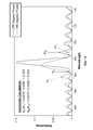
- FIG. 4 are graphs illustrating a single and a composite reflectance spectrum read from an embodiment of microtags without any normalization.
- the upper graph shows the positions of 8 optically read peaks based on the pore density in a microtag.
- the lower graph shows a composite of each of the 8 peaks read back from a set of tags from 9 identically made films from multiple wafers.
- variations in peak energy (position) are such that one cannot immediately discern peak position when tags are produced in quantity utilizing the majority of a single, 4′′ wafer surface.
- FIG. 5A are graphs illustrating embodiments of normalized peak energies.
- the peaks in the upper plot are normalized by using the lowest and highest energy peaks as references and rescaling the peak energy.
- the relative peak energy is actually well maintained. This allows information to be encoded in peak position despite the observed manufacturing process variations in peak position.
- the top panel shows the same data that is plotted in the bottom panel of FIG. 4 , but with the energy of each point rescaled using the lowest and highest energy peaks in each spectrum as reference markers.
- the rescaled energy scale measures the position of every peak in each spectrum as a fraction of the energy difference between the two reference peak positions.
- 5A uses a similar technique (using the amplitude at a given position and rescaling each data point as a fraction of that amplitude) shows that variations in peak amplitude cannot be as handily removed as for the case of variations in peak position.
- a comparison of the amplitude range of the fourth position and the amplitude range at the seventh position illustrates overall range variation; moreover, the amplitudes do not resolve in discrete clusters of amplitudes at any given position. All measured peaks in this plot were encoded using the same amplitude, so discrete clusters in the y-axis are not expected. The lesson from this plot is that variation in measured peak amplitude is not reduced across the spectrum by normalizing the peak amplitudes.
- Amplitude that cannot be assigned with confidence to a known position, or an amplitude at a given position that cannot be determined with confidence cannot be used to decode a rugate microtag.
- the process variations in the etching of a wafer mean that the values associated with amplitude and some positions in the coding and decoding of rugate particles are potentially lost, which degrades the information capacity of rugate microtags.
- Equation (1) is the average index of refraction of the film
- f t is the temporal frequency of the etching current
- ⁇ e is the etching rate.
- the rugate peak positions change in a way which can, to a good approximation, be removed with linear rescaling in energy (or frequency) (e.g., see top of FIG. 5A ).
- the above energy rescaling method requires that the reference peaks appear in the same place in every spectrum. As such, the reference peaks cannot hold any information.
- an alternate method of storing information is used that inherently includes partial scaling information within each spectrum.
- the method requires restricting peak positions to a discrete number of possible energies. For example, in the spectrum shown in the top panel of FIG. 4 , the rugate peaks are encoded (i.e., the etching waveform is generated and applied to the wafer bath) using etching current frequencies that correspond to seven times a base frequency step between each rugate peak. Thus, each step delineates an allowed rugate peak position, providing 49 possible rugate peak positions. The rugate peak at the lowest scaled energy is then used as the single reference peak. Then next step is to try to determine empirically (“guess”) the number of allowed rugate peak positions that lie between the reference peak and the rugate peak with the highest scaled energy.
- guess empirically
- FIG. 5B is a flow diagram illustrating an embodiment of a process for encoding energy peaks of an identifier.
- a readable spectral range is defined.
- the spectral range is divided into N bins.
- a reference peak is encoded in center of a bin near one end of the spectral range.
- data pattern peaks are encoded in the center of bins within the spectral range.
- FIG. 5C is a flow diagram illustrating an embodiment of a process for decoding energy peaks of an identifier.
- a reference peak position is received in 510 .
- data pattern peaks positions are received in 512 .
- a farthest peak of the data peaks from the reference peak is determined in 514 .
- determine data peak bins by finding lowest error for all potential positions of farthest peak from reference peak.
- a number of bins for peaks are determined (e.g., 65 bins, 50 bins, etc.).
- a readable spectral range is defined, such that no matter how the peaks shift during manufacturing they are still within the spectral range of the reader. That range is divided into N bins, any of which can contain a peak.
- a reference peak is encoded near one end of the spectral range—for example, bin 1 .
- the rest of the peaks in a data pattern are encoded (e.g., etched) to each lie at the center of a bin.
- the reader finds the reference peak (e.g., the peak in bin 1 ) and any other peaks in the range of the reader including the peak the farthest from the reference peak.
- the bin number of the peak farthest from the reference peak is found by assuming a bin number ranging from bin N to the reference bin. For each of these assumed bin numbers, the bin centers are calculated for the whole readable range and each peak assigned to its closest bin center. Then the squared deviation of each peak from its bin center is added together for all peaks in each case, and the highest bin number with the smallest total squared deviation is chosen as most likely.
- FIG. 6 are graphs illustrating an embodiment of allowed rugate peak positions.
- the allowed rugate peak positions (bars) are plotted with the measured peak positions displayed in FIG. 5A (circles) for 3 different guesses for the actual position of the highest scaled energy rugate peak.
- the bottom panel is a zoomed-in look at the middle section of the top panel shows all 49 possible rugate peak positions, with 3 different guesses (applied to the data from FIG. 5A ) for the number of allowed rugate peak positions.
- a closer look at the effect of different guesses at the correspondence between allowed peak positions and measured positions is displayed for a peak near the center of the spectral range. It is clear that the correct guess (49 spaces) provides the only reasonable fit.
- FIG. 7 is a graph illustrating the squared error in measured peak position summed for each peak in a spectrum in one embodiment.
- the squared error in the measured peak position is plotted as a function of different guesses for the actual position of the highest scaled energy peak used as a second reference.
- Each spectrum from FIG. 6 is plotted.
- the empirical accuracy (“goodness”) of each guess is quantified by summing the squared difference of each peak position from the calculated allowed positions for each guess. Then the guess with the lowest squared difference can be taken as the best choice and used for decoding.
- the information capacity is determined by the number of allowed peak positions, the smallest achievable distance between two peaks, and to a lesser extent the largest achievable distance between two peaks.
- the system decodes rugate microtags by calculating values of rugate phase ⁇ i or reliable proxies of rugate phase ⁇ i (individually and collectively, “rugate phase information”).
- rugate phase information does not detract from the information storage mechanisms of the existing art, but adds a new way to store information that can be used to add to the total information capacity of a rugate microtag.
- n(z) is the refractive index variation n of a simple one-peak rugate filter at a function of depth z in an etched film or tag.
- n ⁇ ( z ) n 0 + n a 2 ⁇ sin ⁇ ( 4 ⁇ ⁇ ⁇ ⁇ n 0 ⁇ z ⁇ i + ⁇ i ) Eqn . ⁇ 3
- ⁇ i is the wavelength of the rugate peak
- n 0 is the average refractive index
- n a is the peak-to-peak refractive index variation
- ⁇ i is the rugate phase.
- the reflectivity of the rugate filter, r rug can be adapted as:
- r rug includes the rugate peak and its sidelobes, but not the effects of filter surfaces and interfaces.
- the additional reflectivity in the pure rugate case is solely from the surfaces of the filter. Equation 6 below is for the reflectivity, r s , caused by the interference of internal reflections from the surfaces of a filter immersed in air (the simplest case for discussion purposes), but it is straightforward to extend Equation 4 to include buried interfaces or different immersed media. This discussion will continue the analysis of the simple case of a rugate filter immersed in air.
- Equation 7 above contains 4 terms, two of which (r rug ⁇ r s *+r rug * ⁇ r s ) are the so-called cross terms.
- the cross terms contain all of the interference between r rug and r s .
- FIG. 8 shows the magnitude squared of both r rug and r s for typical conditions and one encoded rugate peak. While
- FIG. 8 is a graph illustrating the squared magnitude of both the surface-derived interference fringes r s and a typical rugate peak r rug in one embodiment.
- 2 has equal intensity maxima across the range of energies
- 2 contains appreciable intensity only near the rugate peak.
- the interference effect depends on the relative position in frequency (or energy) of a rugate peak and the surface-derived interference fringes.
- the surface-derived reflectivity is periodic in energy, comprising of repeating identical maxima and minima. The position of each maximum in frequency, f m , is
- n 0 is the average index of refraction of the film
- t is the total etching time
- ⁇ e is the etching rate.
- the 1/ ⁇ e dependence is the same dependence on etching rate as the rugate peak position. Thus changes in etching rate preserve the relative position of rugate peaks and surface-derived interference fringes, and the interference effects do not depend strongly on etching rate.
- a rugate tag system relies on designing and measuring changes in the reflectance peak positions and amplitudes to store information. This means at least one reference peak must be created in the encoding of tags in order to judge relative peak amplitudes or the relative position of other peaks.
- both the apparent peak amplitude and its position in wavelength depend on the rugate phase. This behavior is due to interference between r rug and r s .
- the system achieves an increase in the information capacity of the microtag by using phase as all or part of a signal rather than considering it noise.
- information is encoded using the phase ⁇ i of a rugate peak in the following way.
- a phase value ⁇ i is chosen for the rugate peak of interest. While ⁇ i can take on any value, values of ⁇ i greater than 2 ⁇ or less than zero result in repetition of spectra created using values from zero to 2 ⁇ . It may be convenient to use values of ⁇ i that lie in any 2 ⁇ range independent of absolute values of ⁇ i .
- ⁇ i is physically encoded by electrochemically etching and creating a nanoporous filter using the rugate index of refraction variation n(z) as shown in Eqn. 1, using the chosen value of rugate phase ⁇ i .
- FIG. 9 is a graph illustrating an embodiment of a calculated rugate filter reflectance spectrum.
- the variation of a rugate filter reflectance spectrum obtained by altering a single-frequency etching waveform by phase alone (constant frequency and amplitude) in a twenty degree increments. In each case only one peak is encoded, at constant wavelength and amplitude. Each spectrum corresponds to a different rugate phase.
- the reflectance spectrum is measured and the result compared to the functional form of R (Eqn. 7), preferably by a fitting algorithm.
- the fitting algorithm may utilize a number of constants as convenient to solve for the parameters of interest. It is not required to solve Equations 4 to 6 in their entirety of detail; it may be adequate to approximate some portions of the equations. For example, in equation 6, in both the numerator and denominator n 0 appears in the same form, which we can define as ⁇ :
- the average refractive index n o is about 1.2, so ⁇ is on the order of 0.1.
- FIG. 10 is a graph illustrating an embodiment of a comparison of full surface-derived reflectance to a simple approximation.
- the dashed line shows the effect of ignoring the exponential term in the denominator.
- the lines are close to the same, with the maximum difference at the top of the peak near 565 nm enlarged in the inset.
- the exponential terms are of order 1, so the exponential term of the denominator is of order 0.01, and can be ignored to produce a very close approximation from a simpler equation.
- the important functional characteristics of Equations 4 to 7 are maintained, it is up to the user to determine the level of granularity that is useful.
- the rugate phase ⁇ i is a parameter of R via Equation 4, once the fitting is complete, the original phase ⁇ i is obtained.
- This method is possible for any or all of the desired parameters used in both the index of refraction variation n(z) (Equation 3) and the functional form of R (Equation 7).
- the fitting is done computationally using only the reflectance spectrum, and without need of a reference peak.
- FIG. 11 are graphs illustrating embodiments of four different etching waveforms of the same frequency and amplitude, but different phases.
- each phase could correspond to a different piece of data.
- four different microtags are encoded using etching current density waveforms, all composed of the same single frequency and the same amplitude, but differing in initial rugate phase ⁇ i . Once manufactured, the reflectance of each microtag is measured.
- FIG. 12 are graphs illustrating an embodiment of simulated reflectance spectra corresponding to the four current density waveforms along with fitted spectra.
- the four current density waveforms correspond to those shown in FIG. 11 (dotted lines) and the fitted spectra are obtained using Eqn. 7 (solid lines).
- a simulated spectrum for each of the four current density waveforms is shown. Equation 7 is fitted to each spectrum by using an algorithm such as non-linear least squares. The output of the fit is a value and uncertainty for each parameter in the fit equation, including rugate phase ⁇ i . Examples of equation 7 calculated for each simulated spectrum are also shown.
- this method enables one to accurately store and read many more different phases than the four used in this example.
- FIG. 9 shows that the rugate phase controls a number of spectral properties, notably the rugate sidelobe asymmetry and the peak width. Elimination of fitting the function R may be useful to reduce computational complexity (hence cost) of the overall system implementation.
- FIG. 13 is a graph illustrating an embodiment of a relation between sidelobe asymmetry and rugate phase.
- a clear indication of rugate phase can be extracted. This is the simplest of numerous techniques that may be used to determine rugate phase from a reflectance spectrum. Of many potential spectral properties that could be used to eliminate fitting the function R and associated computation, yet be able to accurately infer controllable index function variables, the sidelobe asymmetry is particularly convenient to measure, since it requires no reference information.
- phase information can be extracted using as few as two data points, as shown in FIG. 13 ; the two data points can then be used to compute a proxy for rugate phase ⁇ i , in this case sidelobe asymmetry.
- FIG. 14 is a graph illustrating an embodiment two rugate index profiles.
- the graph illustrates two different sine-wave index profiles, differing only by phase (180 degrees and 270 degrees respectively); i.e., FIG.
- FIG. 15 is a graph illustrating an embodiment of side lobe asymmetry calculation for two rugate peaks differing only by phase.
- spectra were calculated using standard optical transfer matrix methods applied to interference of multiple “layers”. Note that in the case of rugate filters, physical “layers” are not discrete, rather they are smoothly and continuously varying.
- Inputs to the matrix were the two rugate index profiles shown in FIG. 14 for a tag thickness L of 15 ⁇ m.
- FIG. 15 shows the resultant rugate peaks that would be produced by each index profile to illustrate computation of sidelobe asymmetry. This method of extracting phase information is called the “sidelobe asymmetry method” and is explained in the next paragraph.
- Sidelobe asymmetry is the quotient obtained by dividing the peak reflectance of the first sidelobe below a major reflectance peak of a rugate microtag by the peak reflectance of the first sidelobe above a major reflectance peak, shown in FIG. 15 .
- the quotient varies smoothly over a range of values of the encoded rugate phase ⁇ i .
- the sidelobe asymmetry can be encoded into a rugate peak, and used to store information.
- Sidelobe asymmetry can be easily computed from the reflectance spectrum of a rugate microtag without the need for curve fitting, as described in the preceding paragraph.
- sidelobe asymmetry can be encoded by adjusting the rugate peak position while maintaining a fixed microtag optical thickness. This method is generally less preferred however, because it may interfere with direct peak position encoding.
- FIGS. 14 and 15 requires precise knowledge of the relative position in wavelength between the rugate peak and the nearby surface-derived interference fringes, the quality of which is primarily dependent upon the quality of the spectrometer and signal processing used during interrogation and readout of a rugate particle.
- either simplified methods such as using sidelobe asymmetry method described above
- more computationally intensive fitting methods can be used to extract ⁇ i or other basic parameters from the measured reflectance spectra of rugate filters.
- Additional examples of fitting methods include any form of non-linear regression analysis, such as the non-linear least squares method.
- Phase encoding of information can utilize the number of different phase values ⁇ i , determinable after consideration of manufacturing and reflectance measurement variations, as well as consideration of system decoding tolerances and error correction (ECC).
- ECC error correction
- channel coding maps information bits (b) into physical media (known as “channel coding”) that are well known in information theory and in such industries as the telecommunications, hard disk drive, flash memory, and optical data storage industries (e.g., algebraic codes for data transmission).
- 2 b p that relates the number of values p required to provide b binary digits (“bits”)
- 4 distinct values of ⁇ i could provide 2 bits of raw information capacity
- 8 values of ⁇ i could provide 3 bits of raw information capacity
- Channel codes and ECC extract an overhead to provide for additional robustness and efficiency during the measurement and decoding process, such that information bits available to the end user should be distinguished from raw (or maximum theoretical) capacity available, as is well known in the field.
- phase information can be done for every determinable rugate peak in the reflectance spectrum of a tag to further increase information capacity.
- the encoded information can be useful for means of labeling or authenticating various products or objects when the films, or pieces thereof, are attached to, or embedded within a product, object, or other item.
- the encoded information is used to label or authenticate one or more of the following: a powder, a pill, a liquid drug, an art piece, a chip, a consumer device, an electronic device, or any other appropriate object that it is desired to label or authenticate.
- information encoded in a microtag is used to determine whether or not an item is as desired. For example, an object is labeled using a microtag; the tag is read and the read tag is compared to a known tag signature associated with the object.
- phase tags e.g., the rugate microtags
- wavelength peak amplitude and/or position
- a method and system of encoding, manufacturing, and decoding a rugate microtag comprises:
- the method and system storing information in the optical reflectance of the rugate microtag comprises:
- the method of calculating the rugate phase of each sinusoidal component of an etching current waveform used in the production of a rugate microtag from analysis of the optical reflectance of the rugate microtag comprises:
- the method of calculating the peak wavelength of each rugate component of an etching current waveform used in the production of a rugate microtag from analysis of the optical reflectance of the rugate microtag comprises:
- a reflectance spectrum is measured from a rugate microtag, and the amplitude, frequency (and/or scaled energy), and rugate phase of each sinusoidal component of the etching current are determined based on the measured rugate peaks.
- the method of calculating the peak amplitude components of an etching current waveform used in the production of a rugate microtag from analysis of the optical reflectance of the rugate microtag comprises:
- the method of decoding a rugate microtag wherein the collection of traits for components of an etching current waveform used in the production of a rugate microtag are decoded using one of the preceding methods.
Landscapes
- Physics & Mathematics (AREA)
- Engineering & Computer Science (AREA)
- General Physics & Mathematics (AREA)
- Theoretical Computer Science (AREA)
- Health & Medical Sciences (AREA)
- Electromagnetism (AREA)
- General Health & Medical Sciences (AREA)
- Toxicology (AREA)
- Artificial Intelligence (AREA)
- Computer Vision & Pattern Recognition (AREA)
- Investigating Or Analysing Materials By Optical Means (AREA)
- Investigating, Analyzing Materials By Fluorescence Or Luminescence (AREA)
Abstract
Description
ω in
R=(r rug +r s)·(r rug +r s)*=|r rug|2 +|r s|2 +r rug *·r s +r rug *·r s* Eqn. 7
where n0 is the average index of refraction of the film, t is the total etching time, and νe is the etching rate. The 1/νe dependence is the same dependence on etching rate as the rugate peak position. Thus changes in etching rate preserve the relative position of rugate peaks and surface-derived interference fringes, and the interference effects do not depend strongly on etching rate.
Claims (26)
Priority Applications (10)
| Application Number | Priority Date | Filing Date | Title |
|---|---|---|---|
| US12/966,901 US8511557B2 (en) | 2009-12-19 | 2010-12-13 | Labeling and authenticating using a microtag |
| PCT/US2010/003204 WO2011075173A2 (en) | 2009-12-19 | 2010-12-16 | Labeling and authenticating using a microtag |
| EP10838028.8A EP2513654B1 (en) | 2009-12-19 | 2010-12-16 | Labeling and authenticating using a microtag |
| HK13103827.8A HK1176997A1 (en) | 2009-12-19 | 2013-03-26 | Labeling and authenticating using a microtag |
| US13/918,729 US8636213B2 (en) | 2009-12-19 | 2013-06-14 | Labeling and authenticating using a microtag |
| US14/103,557 US8833656B2 (en) | 2009-12-19 | 2013-12-11 | Labeling and authenticating using a microtag |
| US14/451,284 US9251452B2 (en) | 2009-12-19 | 2014-08-04 | Labeling and authenticating using a microtag |
| US14/979,119 US9501670B2 (en) | 2009-12-19 | 2015-12-22 | Labeling and authenticating using a microtag |
| US15/298,126 US9798903B2 (en) | 2009-12-19 | 2016-10-19 | Labeling and authenticating using a microtag |
| US15/710,726 US10078766B2 (en) | 2009-12-19 | 2017-09-20 | Labeling and authenticating using a microtag |
Applications Claiming Priority (2)
| Application Number | Priority Date | Filing Date | Title |
|---|---|---|---|
| US28828909P | 2009-12-19 | 2009-12-19 | |
| US12/966,901 US8511557B2 (en) | 2009-12-19 | 2010-12-13 | Labeling and authenticating using a microtag |
Related Child Applications (1)
| Application Number | Title | Priority Date | Filing Date |
|---|---|---|---|
| US13/918,729 Continuation US8636213B2 (en) | 2009-12-19 | 2013-06-14 | Labeling and authenticating using a microtag |
Publications (2)
| Publication Number | Publication Date |
|---|---|
| US20110147456A1 US20110147456A1 (en) | 2011-06-23 |
| US8511557B2 true US8511557B2 (en) | 2013-08-20 |
Family
ID=44149675
Family Applications (8)
| Application Number | Title | Priority Date | Filing Date |
|---|---|---|---|
| US12/966,901 Active 2031-04-18 US8511557B2 (en) | 2009-12-19 | 2010-12-13 | Labeling and authenticating using a microtag |
| US12/966,887 Expired - Fee Related US8453929B2 (en) | 2009-12-19 | 2010-12-13 | Producing a microtag identifier |
| US13/918,729 Active US8636213B2 (en) | 2009-12-19 | 2013-06-14 | Labeling and authenticating using a microtag |
| US14/103,557 Active US8833656B2 (en) | 2009-12-19 | 2013-12-11 | Labeling and authenticating using a microtag |
| US14/451,284 Active US9251452B2 (en) | 2009-12-19 | 2014-08-04 | Labeling and authenticating using a microtag |
| US14/979,119 Active US9501670B2 (en) | 2009-12-19 | 2015-12-22 | Labeling and authenticating using a microtag |
| US15/298,126 Active US9798903B2 (en) | 2009-12-19 | 2016-10-19 | Labeling and authenticating using a microtag |
| US15/710,726 Active US10078766B2 (en) | 2009-12-19 | 2017-09-20 | Labeling and authenticating using a microtag |
Family Applications After (7)
| Application Number | Title | Priority Date | Filing Date |
|---|---|---|---|
| US12/966,887 Expired - Fee Related US8453929B2 (en) | 2009-12-19 | 2010-12-13 | Producing a microtag identifier |
| US13/918,729 Active US8636213B2 (en) | 2009-12-19 | 2013-06-14 | Labeling and authenticating using a microtag |
| US14/103,557 Active US8833656B2 (en) | 2009-12-19 | 2013-12-11 | Labeling and authenticating using a microtag |
| US14/451,284 Active US9251452B2 (en) | 2009-12-19 | 2014-08-04 | Labeling and authenticating using a microtag |
| US14/979,119 Active US9501670B2 (en) | 2009-12-19 | 2015-12-22 | Labeling and authenticating using a microtag |
| US15/298,126 Active US9798903B2 (en) | 2009-12-19 | 2016-10-19 | Labeling and authenticating using a microtag |
| US15/710,726 Active US10078766B2 (en) | 2009-12-19 | 2017-09-20 | Labeling and authenticating using a microtag |
Country Status (4)
| Country | Link |
|---|---|
| US (8) | US8511557B2 (en) |
| EP (1) | EP2513654B1 (en) |
| HK (1) | HK1176997A1 (en) |
| WO (2) | WO2011075172A1 (en) |
Cited By (3)
| Publication number | Priority date | Publication date | Assignee | Title |
|---|---|---|---|---|
| CN106022200A (en) * | 2016-05-06 | 2016-10-12 | 江苏南大五维电子科技有限公司 | Encoding and decoding method of spectrum two-dimensional code |
| US10175199B2 (en) | 2012-11-15 | 2019-01-08 | Micro-Tracers, Inc. | Tracer particles, and methods for making same |
| US10482361B2 (en) | 2015-07-05 | 2019-11-19 | Thewhollysee Ltd. | Optical identification and characterization system and tags |
Families Citing this family (8)
| Publication number | Priority date | Publication date | Assignee | Title |
|---|---|---|---|---|
| US8511557B2 (en) * | 2009-12-19 | 2013-08-20 | Trutag Technologies, Inc. | Labeling and authenticating using a microtag |
| US9677935B2 (en) * | 2014-11-03 | 2017-06-13 | Trutag Technologies, Inc. | Fabry-perot spectral image measurement |
| US20160292386A1 (en) * | 2015-04-06 | 2016-10-06 | Trutag Technologies, Inc. | Systems and architecture for electronic interfaces and complex data structures for medication reconciliation and patient regimen adherence detection |
| US10024717B2 (en) * | 2015-11-24 | 2018-07-17 | Trutag Technologies, Inc. | Tag reading using targeted spatial spectral detection |
| US10762407B2 (en) * | 2017-04-05 | 2020-09-01 | General Electric Company | Component incorporating 3-D identification code |
| CN111357027A (en) * | 2018-10-26 | 2020-06-30 | 合刃科技(深圳)有限公司 | Spectrum anti-counterfeiting identification system and spectrum anti-counterfeiting code coding and decoding method |
| EP4008320A4 (en) | 2019-08-02 | 2023-08-09 | Qualicaps Co., Ltd. | Hard capsule formulation sealed with band seal including tag |
| WO2024153691A1 (en) | 2023-01-19 | 2024-07-25 | Capsugel Belgium Nv | Gravure printing cylinder for printing of large-sized tags |
Citations (8)
| Publication number | Priority date | Publication date | Assignee | Title |
|---|---|---|---|---|
| US5432638A (en) | 1992-04-03 | 1995-07-11 | Hughes Aircraft Company | Spatially tunable rugate narrow reflection band filter and applications therefor |
| US5488511A (en) | 1992-04-03 | 1996-01-30 | Hughes Aircraft Company | Spatially tunable rugate narrow reflection band filter |
| US20060255008A1 (en) | 2003-08-14 | 2006-11-16 | Link Jamie R | Photonic sensor particles and fabrication methods |
| US20070036553A1 (en) * | 2005-02-18 | 2007-02-15 | Shahab Etemad | Phase chip frequency-bins optical code division multiple access |
| US20080149731A1 (en) | 2004-01-23 | 2008-06-26 | Semiconductor Energy Laboratory Co., Ltd. | Id Label, Id Card, and Id Tag |
| US20080240649A1 (en) | 2007-03-26 | 2008-10-02 | Eric Korevaar | Optical switch with co-axial alignment beam |
| US20080296255A1 (en) | 2004-07-19 | 2008-12-04 | Sailor Michael J | Magnetic Porous Particles and Method of Making |
| US20090274298A1 (en) | 2008-04-23 | 2009-11-05 | Heidelberger Druckmaschinen Ag | Method for producing a security feature on a flat substrate |
Family Cites Families (2)
| Publication number | Priority date | Publication date | Assignee | Title |
|---|---|---|---|---|
| AU2004308380A1 (en) * | 2003-12-22 | 2005-07-14 | The Regents Of The University Of California | Optically encoded particles, system and high-throughput screening |
| US8511557B2 (en) * | 2009-12-19 | 2013-08-20 | Trutag Technologies, Inc. | Labeling and authenticating using a microtag |
-
2010
- 2010-12-13 US US12/966,901 patent/US8511557B2/en active Active
- 2010-12-13 US US12/966,887 patent/US8453929B2/en not_active Expired - Fee Related
- 2010-12-16 WO PCT/US2010/003203 patent/WO2011075172A1/en active Application Filing
- 2010-12-16 WO PCT/US2010/003204 patent/WO2011075173A2/en active Application Filing
- 2010-12-16 EP EP10838028.8A patent/EP2513654B1/en active Active
-
2013
- 2013-03-26 HK HK13103827.8A patent/HK1176997A1/en not_active IP Right Cessation
- 2013-06-14 US US13/918,729 patent/US8636213B2/en active Active
- 2013-12-11 US US14/103,557 patent/US8833656B2/en active Active
-
2014
- 2014-08-04 US US14/451,284 patent/US9251452B2/en active Active
-
2015
- 2015-12-22 US US14/979,119 patent/US9501670B2/en active Active
-
2016
- 2016-10-19 US US15/298,126 patent/US9798903B2/en active Active
-
2017
- 2017-09-20 US US15/710,726 patent/US10078766B2/en active Active
Patent Citations (8)
| Publication number | Priority date | Publication date | Assignee | Title |
|---|---|---|---|---|
| US5432638A (en) | 1992-04-03 | 1995-07-11 | Hughes Aircraft Company | Spatially tunable rugate narrow reflection band filter and applications therefor |
| US5488511A (en) | 1992-04-03 | 1996-01-30 | Hughes Aircraft Company | Spatially tunable rugate narrow reflection band filter |
| US20060255008A1 (en) | 2003-08-14 | 2006-11-16 | Link Jamie R | Photonic sensor particles and fabrication methods |
| US20080149731A1 (en) | 2004-01-23 | 2008-06-26 | Semiconductor Energy Laboratory Co., Ltd. | Id Label, Id Card, and Id Tag |
| US20080296255A1 (en) | 2004-07-19 | 2008-12-04 | Sailor Michael J | Magnetic Porous Particles and Method of Making |
| US20070036553A1 (en) * | 2005-02-18 | 2007-02-15 | Shahab Etemad | Phase chip frequency-bins optical code division multiple access |
| US20080240649A1 (en) | 2007-03-26 | 2008-10-02 | Eric Korevaar | Optical switch with co-axial alignment beam |
| US20090274298A1 (en) | 2008-04-23 | 2009-11-05 | Heidelberger Druckmaschinen Ag | Method for producing a security feature on a flat substrate |
Cited By (4)
| Publication number | Priority date | Publication date | Assignee | Title |
|---|---|---|---|---|
| US10175199B2 (en) | 2012-11-15 | 2019-01-08 | Micro-Tracers, Inc. | Tracer particles, and methods for making same |
| US10482361B2 (en) | 2015-07-05 | 2019-11-19 | Thewhollysee Ltd. | Optical identification and characterization system and tags |
| CN106022200A (en) * | 2016-05-06 | 2016-10-12 | 江苏南大五维电子科技有限公司 | Encoding and decoding method of spectrum two-dimensional code |
| CN106022200B (en) * | 2016-05-06 | 2018-10-02 | 江苏南大五维电子科技有限公司 | A kind of coding and decoding methods of spectrum two-dimensional code |
Also Published As
| Publication number | Publication date |
|---|---|
| US20140346235A1 (en) | 2014-11-27 |
| US8453929B2 (en) | 2013-06-04 |
| US20180025186A1 (en) | 2018-01-25 |
| EP2513654A4 (en) | 2013-08-21 |
| EP2513654A2 (en) | 2012-10-24 |
| US20170039400A1 (en) | 2017-02-09 |
| US20160110568A1 (en) | 2016-04-21 |
| US20140001260A1 (en) | 2014-01-02 |
| US10078766B2 (en) | 2018-09-18 |
| US8636213B2 (en) | 2014-01-28 |
| US9798903B2 (en) | 2017-10-24 |
| WO2011075173A2 (en) | 2011-06-23 |
| WO2011075172A1 (en) | 2011-06-23 |
| US20140097245A1 (en) | 2014-04-10 |
| WO2011075173A3 (en) | 2011-08-04 |
| US20110147458A1 (en) | 2011-06-23 |
| US20110147456A1 (en) | 2011-06-23 |
| US8833656B2 (en) | 2014-09-16 |
| HK1176997A1 (en) | 2013-08-09 |
| US9501670B2 (en) | 2016-11-22 |
| EP2513654B1 (en) | 2015-02-18 |
| US9251452B2 (en) | 2016-02-02 |
Similar Documents
| Publication | Publication Date | Title |
|---|---|---|
| US10078766B2 (en) | Labeling and authenticating using a microtag | |
| US11875501B2 (en) | Information coding in dendritic structures and tags | |
| US10289875B2 (en) | Embedding data on objects using surface modulation | |
| US10223567B2 (en) | Dendritic structures and tags | |
| US20200117882A1 (en) | Polarized scanning of dendritic identifiers | |
| US8459567B2 (en) | Non-linear strain gage incorporating a nested binary code symbol | |
| US20110049250A1 (en) | Nested binary code symbol | |
| US20060231625A1 (en) | Security label which is optically read by terahertz radiation | |
| CN104937381B (en) | Measurement scales | |
| US20210157888A1 (en) | Secure access with dendritic identifiers | |
| CN104657979A (en) | Ultrasonic image feature detection method and system | |
| Zgardzińska | Can Tao-Eldrup Model Be Used at Short o-Ps Lifetime? | |
| Velázquez Galván et al. | Bistable magnetic nanowires: A new approach to non-volatile memory with single readout and automatic deletion | |
| CN117388185A (en) | Hyperspectral material identification method and device, electronic equipment and storage medium | |
| US20230193134A1 (en) | Structures for physical unclonable function using spontaneous chiral symmetry breaking and method of preparing the same | |
| JP2003506792A (en) | Encoding label information extraction method | |
| El Kodadi et al. | Dynamic scatterometry for profile control during resist trimming process | |
| Wolski et al. | Texture analysis of self-structured surfaces in formation process using directional fractal signature method |
Legal Events
| Date | Code | Title | Description |
|---|---|---|---|
| AS | Assignment |
Owner name: CELLULAR BIOENGINEERING, INC., HAWAII Free format text: ASSIGNMENT OF ASSIGNORS INTEREST;ASSIGNORS:LEARMONTH, TIMOTHY;ZHOU, TING;SIGNING DATES FROM 20110210 TO 20110216;REEL/FRAME:025874/0990 |
|
| AS | Assignment |
Owner name: TRUTAG TECHNOLOGIES, INC., HAWAII Free format text: ASSIGNMENT OF ASSIGNORS INTEREST;ASSIGNOR:CELLULAR BIOENGINEERING, INC.;REEL/FRAME:029290/0924 Effective date: 20121019 |
|
| STCF | Information on status: patent grant |
Free format text: PATENTED CASE |
|
| FPAY | Fee payment |
Year of fee payment: 4 |
|
| MAFP | Maintenance fee payment |
Free format text: PAYMENT OF MAINTENANCE FEE, 8TH YEAR, LARGE ENTITY (ORIGINAL EVENT CODE: M1552); ENTITY STATUS OF PATENT OWNER: LARGE ENTITY Year of fee payment: 8 |
|
| AS | Assignment |
Owner name: FIRST-CITIZENS BANK & TRUST COMPANY, CALIFORNIA Free format text: SECURITY INTEREST;ASSIGNOR:TRUTAG TECHNOLOGIES, INC.;REEL/FRAME:066140/0667 Effective date: 20231215 |
|
| AS | Assignment |
Owner name: KUMUKAHI HOLDINGS, INC., HAWAII Free format text: NON-RECOURSE ASSIGNMENT OF INTELLECTUAL PROPERTY SECURITY AGREEMENT;ASSIGNOR:FIRST-CITIZENS BANK & TRUST COMPANY;REEL/FRAME:069083/0367 Effective date: 20240221 Owner name: TRUTAG TECHNOLOGIES, INC., CALIFORNIA Free format text: PARTIAL RELEASE AND TERMINATION OF SECURITY INTEREST IN PATENTS;ASSIGNOR:KUMUKAHI HOLDINGS, INC.;REEL/FRAME:069054/0217 Effective date: 20240927 Owner name: OPSEC SECURITY, INC., PENNSYLVANIA Free format text: ASSIGNMENT OF ASSIGNORS INTEREST;ASSIGNOR:TRUTAG TECHNOLOGIES, INC.;REEL/FRAME:068751/0477 Effective date: 20240927 |